Page 1234 of 1395

Integrated Control Unit
A1 --------> A7
Input Test -'98 - 00 Models (cont'dl
YEL/BLULT GRNWHT/BLK
GRN/BLKLT GRN/REO
Wire side offemale terminals
A8------->A14WHT/BLK
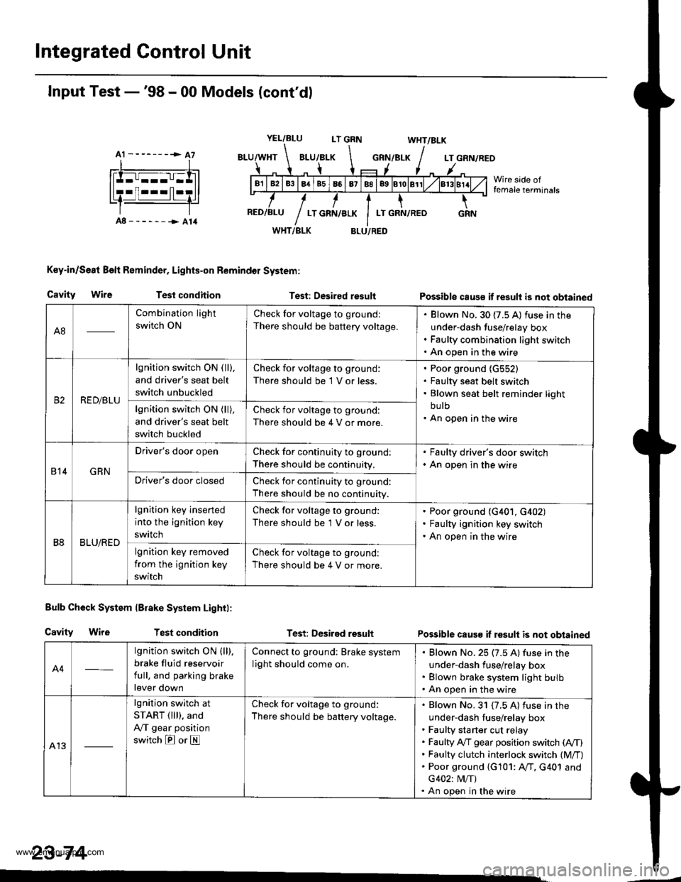
Key-in/Se8t Beft Reminder, Lights-on Remindol System:
BLU/RED
Cavity WireTest conditionTest: Desired resultPossible caus€ it result is not obtained
Bulb Check System lBrake System Lightl:
Cavity WireTest conditionTest: Desired resultPossible caus€ if result is not obtained
A4
lgnition switch ON (ll),
brake fluid reservoir
full, and parking brake
lever down
Connect to ground: Brake system
light should come on.
Blown No. 25 (7.5 A) fuse in the
under-dash fuse/relay box
Blown brake system light bulb
An open in the wire
A13
lgnition switch at
START ( lll), and
A,/T gear position
switch E or E
Check for voltage to ground:
There should be battery voltage.
Blown No. 31 {7.5 A) fuse in the
under-dash fuse/relay box
Faulty sta rter cut relay
Faulty A,/T gear position switch (A,/T)
Faulty clutch interlock switch (M/T)
Poor ground {G101: AfI. G401 and
G402: M/T)
An open in the wire
23-74
A8
Combination light
switch ON
Check for voltage to ground:
There should be battery voltage.
Blown No. 30 (7.5 A) fuse in the
under-dash fuse/relay box
Faulty combination light switch
An open in the wire
RED/BLU
lgnition switch ON ( ll),
and driver's seat belt
switch unbuckled
Check for voltage to ground:
There should be 1 V or less.
Poor ground {G552)
Faulty seat belt switch
Blown seat belt reminder light
bu lb
An open in the wirelgnition switch ON (ll),
and driver's seat belt
switch buckled
Check for voltage to ground:
There should be 4 V or more.
814GRN
Driver's door openCheck for continuity to ground:
There should be continuity,
. Faulty driver's door switch. An open in the wire
Driver's door closedCheck for continuity to ground:
There should be no continuity.
B8BLU/RED
lgnition key inserted
into the ignition key
swrtch
Check for voltage to ground:
There should be 'l V or less.
Poor ground (G401, G402)
Faulty ignition key switch
An open in the wire
lgnition key removed
from the ignition key
switch
Check for voltage to ground:
There should be 4 V or more.
www.emanualpro.com
Page 1288 of 1395
Power Door Locks
Driver's Door Lock Knob Switch Test
1. Remove the driver's door panel (see section 20).
2. Disconnect the 6P connector from the actuator.
Terminalside otmale terfiinals
Check for continuity between the terminals in each
switch position according to the table.
rsrmrnal
Position \
?6
LOCKo--o
UNLOCKo---o
23-128
.
6P CONNECTOR
Driver's Door Lock Actuator Test
1, Remove the driver's door panel (see section 20).
2. Disconnect the 6P connector from the actuator.
Terminal side ofmale terminals
Check actuator operation by connecting power and
ground according to the table. To prevent damsge
to the actuator. apply battery voltage only momen-
tarilv,
6P CONNECTOR
Terminal
F*'',1."
__l
LOCK@o
UNLOCK@
'-
www.emanualpro.com
Page 1289 of 1395
Passenger's Door Lock Actuator Test
Remove the passenger's door panel (see section 20).
Disconnect the 2P connector from the actuator.
NOTE: The left rear door lock actuator is shown;
the front passenger's and right rear door lock actua-
tors are similar.
Terminal side ofmale terminals
Check actuator operation by connecting power and
ground according to the table. To prevent damage
to the actuator, apply battery voltage only momen-
raflry.
Terminal
;;il;--r
,l
LOCK@
UNLOCK@
1.
2P CONNECTOR
4. lf the actuator does not work properly, replace it.
23-129
L
Driver's Door Lock Switch Test
Remove the inner handle {see section 20).
Disconnect the 3P connector. then remove the two
mounting screws and driver's door lock switch.
Check for continuitv between the terminals in each
switch position according to the table.
lermlnal
Position \
123
LOCKo---o
OFF
UNLOCKo--_o
www.emanualpro.com
Page 1294 of 1395
Power Windows
Master Switch Input Test
NOTE: The control unit is built into the power window master switch and only controls driver's door window operations.
1. Remove the master switch, and disconnect the 14P,2? and 1P connectors from the master switch.
2. Inspect the connector and socket terminals to be sure they are all making good contact.
. lf the terminals are bent, loose or corroded, repair them as necessary, and recheck the system,
. lf the terminals look OK, make the following input tests at the connector.- lf a test indicates a problem, find and correct the cause, then recheck the system.- lf all the input tests prove OK, the power window maser switch must be faulty; replace it.
1P CONNECTOR
BLU/ORN RED/BLUYEL/BLK
BLU/YEL RED/YELGRN
GRN/YEL
POWER WINDOW MASTEB SWITCH
GRN/BLK aLu/BLK BLK RED/WHT YEL/GRN YEL
Wire side offemale terminals
RED/BLK
lirP CONNECTOR
23-134
Wire side oIfemale terminals
.-
www.emanualpro.com
Page 1297 of 1395

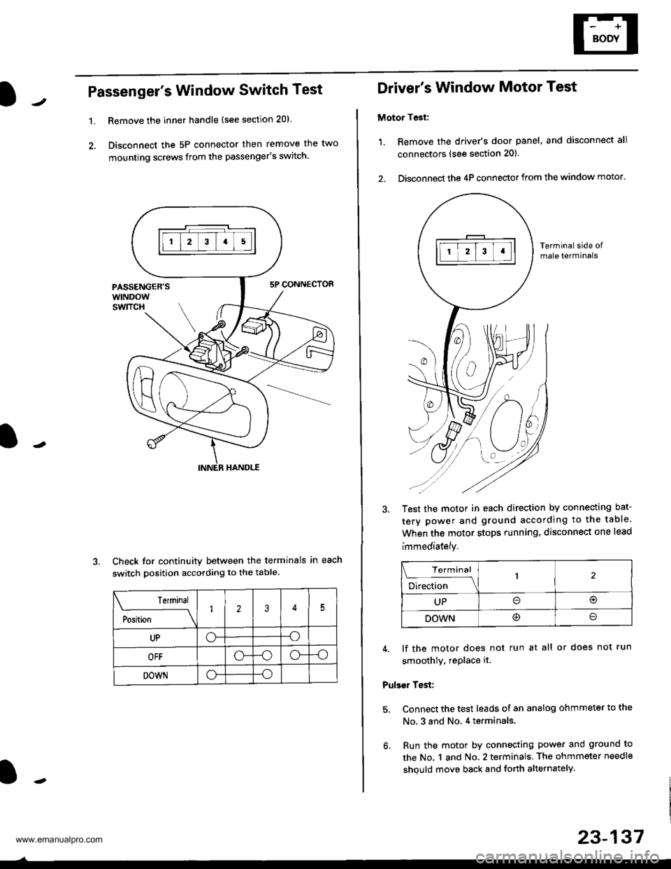
Passenger's Window Switch Test
1.Remove the inner handle (see section 20).
Disconnect the 5P connector then remove the two
mounting screws from the passenger's switch.
Check for continuity between the terminals in each
switch position according to the table
Terminal
;"rL-
__\1235
UPo--o
OFF-oo--o
DOWNo--o
Driver's Window Motor Test
Motor Test:
1. Remove the driver's door panel, and disconnect all
connectors (see section 201.
2. Disconnect the 4P connector from the window motor.
Terminal side ofmale terminals
Test the motor in each direction by connecting bat-
tery power and ground according to the table.
When the motor stops running. disconnect one lead
immediately.
Terminal
;;b"
-\
UPo(!r
DOWN@o
4. lf the motor does not run at all or does not run
smoothly. rePlace it.
Pulser Test:
5. Connect the test leads of an analog ohmmeter to the
No, 3 and No. 4 terminals.
6. Run the motor by connecting power and ground to
the No. 1 and No. 2 terminals. The ohmmeter needle
shquld move back and forth alternately.
23-137
www.emanualpro.com