Page 1078 of 1395
Wiper/Washer
Component Location Index
WINOSHIELD WIPER ARMS
and LINKAGEReplacement, page 20-98
Adiustment, Page 20-103
REAR WINDOW WIPERARM and MOTORReplacement, page 20 99Adiustment, page 20 103
WASHER RESERVOINReplacement, page 20 99WASHER TUBEReplacement, page 20-100
20-97
www.emanualpro.com
Page 1079 of 1395

Wiper/Washer
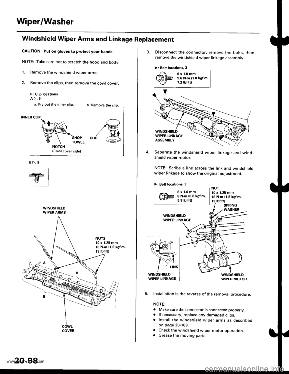
Windshield Wiper Arms and Linkage Replacement
CAUTION: Put on gloves to protoct your hands.
NOTE: Take care not to scratch the hood and body.
1. Remove the windshield wiper arms.
2. Remove the clips, then remove the cowl cover.
>: Clip locationsA>.9
b. Remove the clip.
SHOPTOWEL
(Cowl cover side)
/G
"rr/ &
a. Pry out the anner clip.
INNER CLIP
B>.8
ql
WINDSHIELDWIPER ARMS
NUTS'10 x 1.25 mm18 N.m 11.8 kgf.m.13 tbf.ftl
COVER
20-98
3. Disconnect the connector, remove the bolts, then
remove the windshield wiper linkage assembly.
>: Boh locations,3
4. Separate the windshield wiper linkage and wind-shield wiper motor.
NOTE: Scribe a line across the link and windshieldwiper linkage to show the original adjustment.
>: Boh locations, 3
s}@
1ffi,
/Y{
/
' L|NK
WINDSHIELDWIPER LIN(AGEWIPER MOTOR
5. Installation is the reverse of the removal procedure.
NOTE:
. Make sure the connector is connected properly.. lf necessary. replace any damaged clips.. Install the windshield wiper arms as describedon page 20-103.
. Check the windshield wiper motor operation.. Grease the moving parts.
6x1.0mm9.8 N.m (1.0 kglm,7.2 tbt.fr)
6x1.0mm8 N.m 10.8 kgf.m,5.8 lbf.ftl
NUT10 x 1.25 mm18 N.m 11.8 kgf.m,13 tbf.ftlSPRINGWASHER
www.emanualpro.com
Page 1080 of 1395

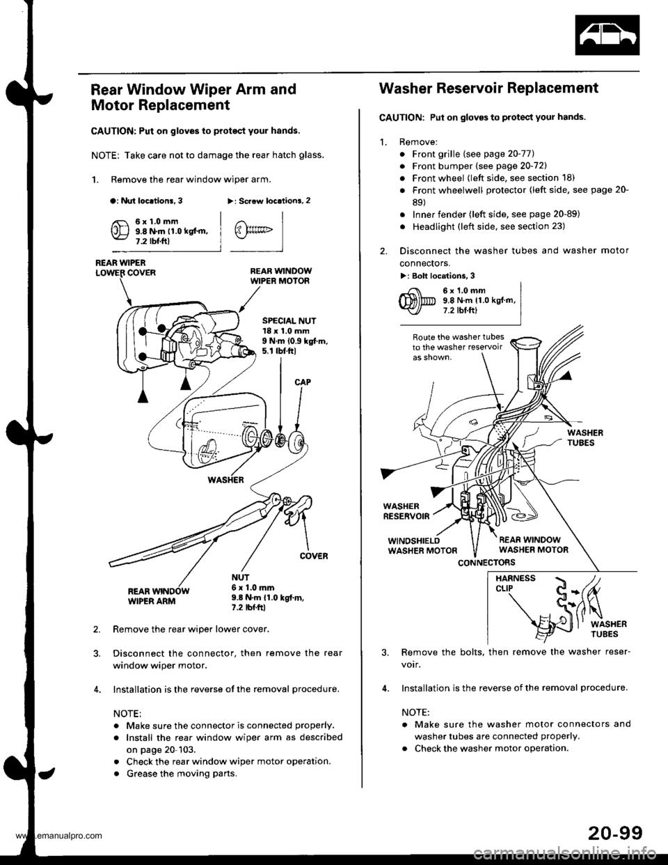
Rear Window Wiper Arm and
Motor Replacement
CAUTION: Put on gloves to protect your hands.
NOTE; Take care not to damage the rear hatch glass.
1. Remove the rear window wiper arm.
a: Nut loc.tion!, 3>: Scaow locationa, 2
REAR WINDOWWIPER MOIOR
REAR WIPERCOVER
REARWIPER ARM
6x1.0mm9.8 N.m 11.0 kgt'm,7.2 tbf.ftl
SPECIAL NUT18 x 1.0 mm9 N.m 10.9 kgt m,5. r tbt.ftl
NUT6x 1.0mm9.8 N.m {1.0 kgt.m,?.2 tbfftl
Remove the rear wiper lower cover.
Disconnect the connector, then remove the rear
window wiper motor.
Installation is the reverse of the removal procedure.
NOTE:
. Make sure the connector is connected properly.
. Install the rea. window wiper arm as described
on page 20-103.
. Check the rear window wiper motor operation.
. Grease the moving parts.
@rrc
Washer Reservoir Replacement
GAUTION: Put on gloves to protect your hands.
1. Remove:
. Front grille (see page 20-771
. Front bumper (see page 20-721
. Front wheel {left side, see section 18)
. Front wheelwell protector (left side, see page 20-
89)
. Inner fender (left side, see page 20-89)
. Headlight (left side, see section 23)
2. Disconnect the washer tubes and washer motor
connectors.
>: Bolt locations, 3
6x1.0mm9,8 N.m 11.0 kgt.m,7.2 tbt.ftl
Route the washer tubesto the washer teservoir
WASHERRESERVOIR
WINOSHIELOWASHER MOTON
CONNECTORS
3. Remove the bolts, then remove the washer reser-
votr,
4. Installation is the reverse of the removal procedure.
NOTE:
a Make sure the washer motor connectors and
washer tubes are connected properly.
. Check the washer motor operation.
HARNESS / tcLrP C-(fu
- S(ilq
s{J
l' wrsHER
20-99
www.emanualpro.com
Page 1084 of 1395
Wiper Arms and Washer Nozzles Adiustmenl
Wind3hield Wipor/Washer:
1, Adiust the wiper arms so that their park positions
match the illustration.
Viow from flont io roar
GLASS
2. Insert a tack into the washer nozzles. and
them so that they aim at positions A, A', B,
shown in the illustration.
adjust
and B'
Distance
^,J;-ll\
from center
line
from black
ceramic edge
A and A'3,$ mm (13.5 in.)287 mm (11.3 in.)
B and B'122 mm (4.80 in.)352 mm (13.9 in.)
Rear Window wipor/Washer:
Vi6w trom roar to lront
REARsPo[.-ER
C.nlar linoL
Align to the rear windowdefogger grid line.
Distance
ru"rrr. "i.
'_\from center
ltne
from black
ceramic edge
27 mm (1.1 in.)88 mm (3.5 in.)
20-103
www.emanualpro.com
Page 1088 of 1395
Frame Repair Chart
(cont'd)
Side view:
Unit: mm (in.)
0: Inner diamete.
POINT d3
o15 {0.591 For Trensmission Mount
d15 10.591 For Trrnsmi3donMount
POINT d1
t13 10.5'll For Transmb3ionMount
POINT el
613 10.51) For TransmirsionMouni
z
t13 {0,511 For Engin6 Mount
M10 x Pl.25
t13 10.51) For Uppcr Arm
.25
POINT,1710.67)Fof Re.r Beam
o12 (0.,171 For Right Front Stop
POINT c1
o16 10.631 Locate Hole
612 {0.47} For Left Front Stoo
b2
r12 {0.47) For Left Front StoD
t5011.97| Locrt. Hol.
POINT
t17 10.671 Fo. R..r
r'17 10.671 For Rcar Bo.mt12 {0.47} For Right Front Stop
POINT c2
130POINT h1
DamperLower BushingPoint
o11 (0.{31 For Engine Mount
20-108
www.emanualpro.com
Page 1089 of 1395
POlNTx.y / I
'sad
POINT m3, m4
Upper Arm
M12 x P1.25
Locate Hole
POINT 3, s1
o14 {0.551 For Trailing Aim
POINT v
Fuel Tank Strap Poinr
2700.5 (106.32)SECTION BBRear Damoer Center
POINT n
FOINT
rg (0.3) Fuel TStrap Center
271,1(10,6.9)
o2010.8| Locate Hole
For Rear Cros3 Beam
For Reer Cross Beam
POINT w
Bear Damper LowerBushing Point
I
\-
ql
ol
.df
20-109
www.emanualpro.com
Page 1100 of 1395

Troubleshooting
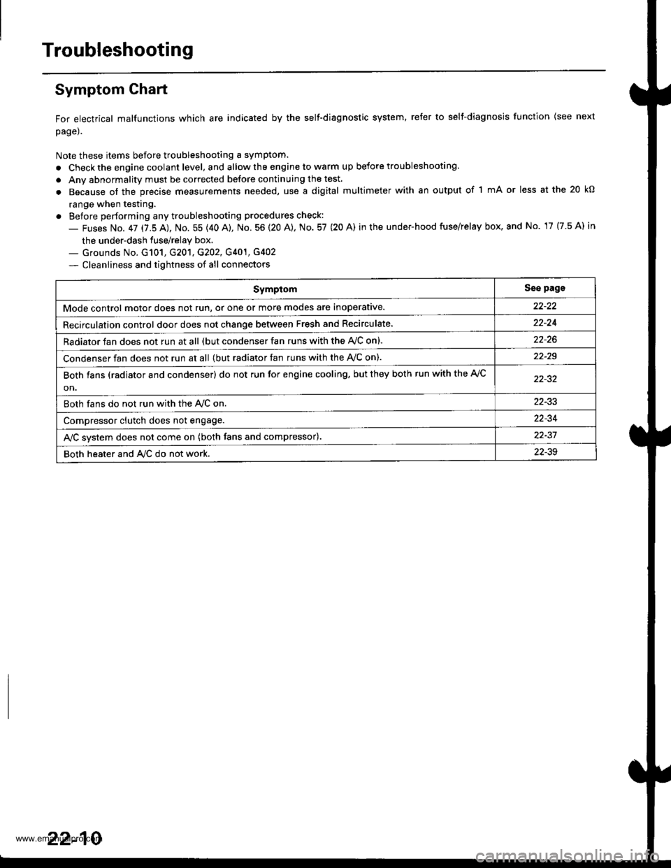
Symptom Ghart
For electrical malfunctions which are indicated by the self-diagnostic system, reter to selt-diagnosjs function (see next
page).
Note these items before troubleshooting a symptom.
. Check the engine coolant level, and allow the engine to warm up before troubleshooting.
. Anv abnormality must be corrected before continuing the test.
. Because of the precise measurements needed, use a digital multimeter with an output of 1 mA or less at the 20 kO
range when testing.
. Before performing any troubleshooting procedures check:
- Fuses No. 47 17.5 AJ, No. 55 (40 A), No. 56 (20 A), No. 57 (20 A) in the under-hood fuse/relay box, and No. 17 {7.5 A) in
the under-dash fuse/relay box.._ Grounds No. G101, G201, G202, G401, G4O2
- Cleanliness and tightness of all connectors
SymptomSse pags
Mode control motor does not run, or one or more modes are inoperative.
Recirculation control door does not change between Fresh and Recirculate.22-24
Radiator fan does not run at all (but condenser fan runs with the AVC on).
Condenser fan does not run at all {but radiator fan runs with the Ay'C on).22-29
Both fans (radiator and condenser) do not run for engine cooling. but they both run with the A,/C
on.
Both fans do not run with the Ay'C on22-33
Compressor clutch does not engage.22-34
AJC svstem does not come on (both fans and compressor).22-37
Both heater and A/C do not work,22-39
22-10
www.emanualpro.com
Page 1131 of 1395

Mode Control Motor
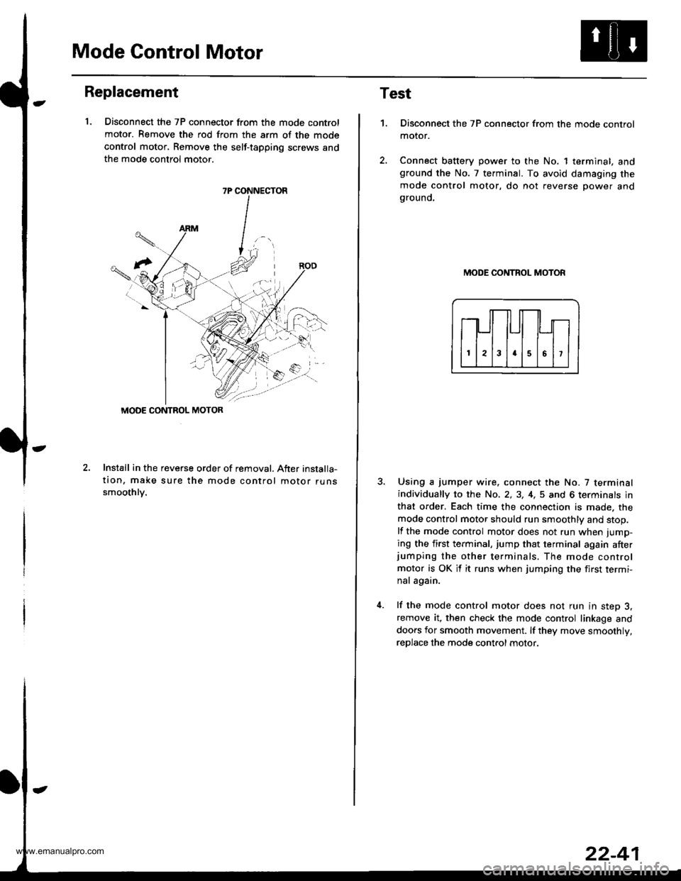
Replacement
1. Disconnect the 7P connector from the mode control
motor. Remove the rod from the arm of the mode
control motor, Remove the self-tapping screws and
the mode control motor.
2.Install in the reveGe order of removal. After installa-
tion, make sure the mode control motor runssmoothlv.
7P CONNECTOR
MODE CONTROL MOTOR
Test
1.Disconnect the 7P connector from the mode control
motor.
Connect battery power to the No. 1 terminal, andground the No. 7 terminal. To avoid damaging the
mode control motor, do not reverse power andgrouno.
MODE CONTROL MOTOR
Using a jumper wire. connect the No. 7 terminalindividually to the No, 2,3, 4,5 and 6 terminals in
that order. Each time the connection is made. the
mode control motor should run smoothly and stop.
lf the mode control motor does not run when jump-
ing the first terminal, jump that terminal again afterjumping the other terminals. The mode control
motor is OK it it runs when jumping the first termi-
nal again.
lf the mode control motor does not run in step 3,remove it, then check the mode control linkage and
doors for smooth movement. lf they move smoothly,
reDlace the mode control motor.
www.emanualpro.com