Page 985 of 1395
Doors
Gomponent Location Index (cont'dl
Rear Door:
NOTE: Refertothe 1997 Series Honda CR-V Bodv RepairManual (P/N 6151030) for rear door removal.
INNER WEATHERSTRIPOUTER MOLOING
DOOR PROTECTION
ARMREST
REAR DOOR('97 -98 models)
HINGE
REAR DOOR PANEL1'99 - 00 models)Removal and Installation,page 20 '11
@
ARMRESTBRACKET
Position Adiustment,page 20-22
tu4
dP
@
o
@
Bemoval and Installation,page 20-11
(Left side only,'97 - 98 models)
\
DOOR CHANNEL TAPE
FR,
)Ei
D\
\a
20-4
('99 - 00 models)
www.emanualpro.com
Page 988 of 1395
Front Door Panel Removal and Installation
NOTE: Take care not to scratch the door panel and other
pans.
L Remove the inner handle (see page 20-3).
2. Remove the speaker cover, then remove the screws.
>: Scr€w locations, 3
SPEAKERCOVER
Remove the screws from the armrest. Release the
clips that hold the door panel, then remove the door
panel by pulling it upward. Disconnect the speaker
connector.
NOTE: Remove the door panel with as little bend-
ing as possible to avoid creasing or breaking it.
TRIM PADREMOVER(Commercially
avaalable)Snap-on*4177, olequivalent
'..4'
,mm +,----ZY"{0.04 in.) r F -i45 mm I
{1.77 in.}
>: Screw location3,
I
eF** Iffil$;^r*l-w.
ttv IilF:I
3 >:Clip locttionsA>, 1 g>,3
FRONT OOOR PANEL
lnstallation is the reverse of the removal procedure.
NOTE: Make sure the connector is plugged in prop-
efly.
20-7
www.emanualpro.com
Page 992 of 1395

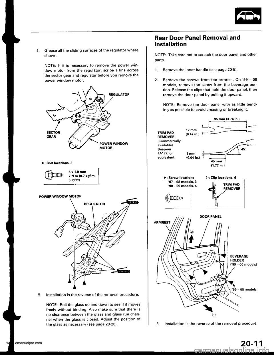
4. Grease all the sliding surfaces of the regulator where
shown.
NOTE: lf it is necessary to remove the power wrn-
dow motor from the regulator, scribe a line across
the sector gear and regulator before you remove the
power window motor.
R€GULATOF
>: Boh locations,3
6x1.0mm7 N.m lo.t kgf.m,5 tbf.ftl
POWER WINOOW MOTOR
REGULATOR
Installation is the reverse of the removal procedure.
NOTEi Rollthe glass up and down to see if it moves
freely without binding. Also make sure that there is
no clearance betlveen the glass and glass run chan
nel when the glass is closed. Adjust the position of
the glass as necessary (see page 20-20).
4
A
m^i
A
Rear Door Panel Removal and
lnstallation
NOTE: Take care not to scratch the door panel and other
parts.
1. Remove the inner handle (see page 20-5).
2. Remove the screws from the armrest. On '99 - 00
models, remove the screw from the beverage por-
tion. Release the clips that hold the door panel, then
remove the door panel by pulling it upward.
NOTE: Remove the door panel with as little bend-
ing as possible to avoid creasing or breaking it.
TBIM PADREMOVER(Commercially
available)Snap-on#4177, orequivalentlmm{0.04 in.)
>: Screw locelions'97 - 98 models. 3'99 - 00 modols, 4
11.77 in.)
DOOB PANEL
ARMREST
o
i
'99 - 00 models:
3. Installation is the reverse of the removal procedure.
\(,1
t_
T r-----/t5 mm I
EEVERAGEHOLDEN('99 00 modelsi
>i Clip locations,6
20-11
www.emanualpro.com
Page 1011 of 1395

Glass
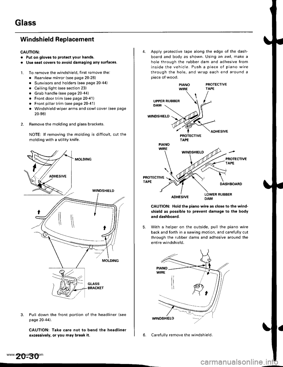
Windshield Replacement
CAUTION:
. Put on gloves to protect your hands.
. Use seat covers to avoid damaging any surfaces.
1. To remove the windshield, first remove the:
. Rearview mirror (see page 20-28)
. Sunvisors and holders (see page 20-44l'
. Ceiling light (see section 23)
. Grab handle (see page 20-44)
. Front door trim (see page 20-41)
. Front pillar trim (see page 20-41)
. Windshield wiper arms and cowl cover (see page
20-98)
2. Remove the molding and glass brackets.
NOTE: lf removing the molding is difficult, cut the
moldlng with a utility knife.
MOLDING
3. Pull down the front Dortion of the headliner (see
page 20-44).
CAUTION: Take care not to bend the headliner
excessivsly, or you may break it.
WINDSHIELD
20-30
4. Apply protective tape along the edge ot the dash-
board and body as shown. Using an awl, make a
hole through the rubber dam and adhesive from
inside the vehicle. Push a piece of piano wire
through the hole, and wrap each end around a
piece of wood.
PROTECTIVETAPE
WINDSHIELD
ADHESIVE
PIANOWIRE
PROTECTIVETAPE
WINDSHIELO
PROTECTIVETAPEDASHBOARD
ADHESIVELOWER RUBBERDAM
CAUTION: Hold the piano wire as close to the wind-
shield as possible to prevent damage to the body
and dashboard.
5. With a helper on the outside, pull the piano wire
back and fo(h in a sawing motion, and carefully cut
through the rubber dams and adhesive around the
entire windshield.
6. Carefully remove the windshield.
UPPER RUBBER
PIANO
www.emanualpro.com
Page 1037 of 1395
Seats
Component Location Index
REAR SEAISRemoval and lnstallation, page 20 63Disassembly and Reassembly, page 20 65Seat Linkage Disassembly and Reassembly, page 20-67Armrest Replacement, page 20-69Seat Cover Replacement, page 20-69
Removal and Installation, page 20 57Disassembly and Reassembly, page 2O-58Seat Linkage Disassembly and Reassembly, page 20-60Armrest Fleplacement, page 20 61Seat Cover Replacernent, page 20 61
20-56
www.emanualpro.com
Page 1042 of 1395
Front Seat Armrest Replacement
NOTE: Take care not to tear the seams or damage the
seat coverS.
>: Bolt locations.2
6r1.0mm9.8 N,m ll.0 kgl.m,7,2 tbf.ft)
10 x 1.25 mm47 N.m 1,1.8 kgf,m,35 tbt{t)
Installation is the reverse of the removal procedure.
Front Seat Cover Replacement
CAUTION: Put on gloves to protect your hands.
NOTE: Take care not to tear the seams or damage the
seat covers.
Seat-back cover:
'1. Slide the front seat forward, and fold the seat-back
forward.
2.
3.
Remove the armrest from the driver's seat.
Release the hook, and fold back the seat-back cover.
4.Release all inside springs, then fold back the seat-
back cover. and remove the clios.
WIRE{Pad sidei
(Seat back frame sjde) cover on '00 model)
(cont'd)
20-61
SEAT-BACK
www.emanualpro.com
Page 1049 of 1395
Seats
Rear Seat Linkage Disassembly and Reassembly (cont'd)
with tilt:
NOTE: Refer to section 24 for the rear seat belt buckles and center belt tongue removal
TILT CONTFOLCABLE10 x 1.25 mm47 N.m {i1.8 kgt.m,35 tbf.ft)
ARM
6x1.0mm9.8 N.m n.0 kgt.m,7.2 tbt.tll
CENTEBCOVER
/
n
//-)
ASE FRAME
8 r 1.25 mm16 N.m (1.6 kgf.m,12 tbt.ftl
DAMPER
6x1.0mm9.8 N.m 11.0 kgtm,7.2 tbttr)
TILT CONTROL ROD
A
@
SPRING
UPPER HINGE
TILTCONTROLCABLE
Replace.
q
BUSHING
E.CLIPReptace.
Reassemble in the reverse order of disassembly.
NOTE:
. Grease the moving ponion.
. lf necessary, adjust the tilt control cable.
20-64
HINGE PIN
www.emanualpro.com
Page 1050 of 1395
Rear Seat Armrest Replacement
NOTE: Take care not to tear the seams or damage the
seat covers.
COLLAR
COLLAR6x1.0mm9.8 N.m {1.0 kgf.m,7.2 rbr.ft)
WASHER
NYLONWASHER
VEARMRESTWASHER
ARMRESTPIVOT BOLT6x1.0mm9.8 N.m (1.0 kgt.m,7.2lbllll
lnstallation is the reverse of the removal procedure.
SEAT.BACK
Rear Seat Cover Replacement
CAUTION: Put on gloves to protect your hands.
NOTE: Take care not to tear the seams or damage the
seal covers.
Seal-back cover:
Remove the seat-back {see page 20-65).
Remove:
a Armrest
. Headrest
. Seat-back recline rod (see page 20-65)
Remove the seat cushion strap bolt and strap bolt
trim, then remove the seat-back mat.
L
2.
"'---.' t.-r" t-- i,': "" '
4. Remove all the clips.
(cont'd)
20-69
www.emanualpro.com