1998 HONDA CIVIC Feed tube
[x] Cancel search: Feed tubePage 277 of 2189

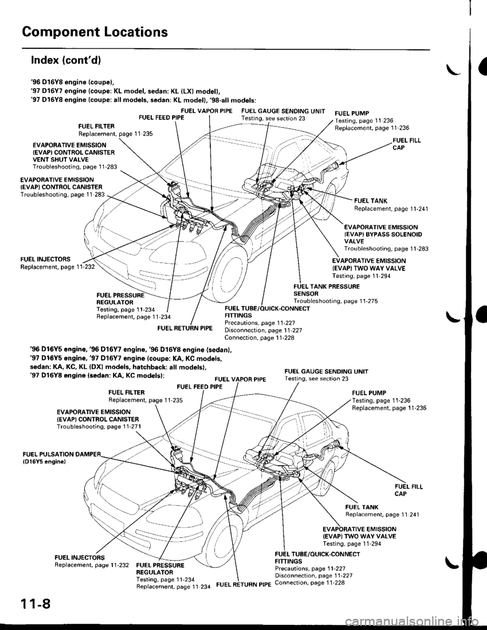
Component Locations
Index (cont'dl
'96 D16Y8 engine (coupel,'97 D16Y7 engine (coupe: KL model, sedan: KL (LXl model),'97 D16Y8 engine (coupe: all models, sedan: KL modell,'98-all models:
FUEI- VAPOR PIPEFUEL FEED PIPEFUEL GAUGE SENDING UNITTesting, see section 23FUEL PUMPTesting, page 11 236Replacement, page 11 236FUEL FILTERReplacement,
€VAPOFATIVE EMISSION(EVAPI CONTROL CANISTERVENT SHUT VALVETroubleshooting, page l1'283
FUEL FILLCAP
FUEL TANKReplacement, page I l-241
EVAPORATIVE EMISSIONIEVAPI CONTROLCANISTERTroubleshooting, page 11 283
EVAPORATIVE EMISSIONIEVAP) BYPASS SOLENOIDVALVETroubleshooting, page 1 1 -283
FUEL INJECTORSReplacement, page 1 1-232EVAPORATIVE EMISSION(EVAPI TWO WAY VALVETesting, page 11 294
FUELREGULATORTesting, page 11-234
TANK PRESSURESENSORTroubleshooting, page 11-275
Replacement, page 1 1-234
'96 Dt6Y5 engine,'96 D16Y7 engin€, '96 D16Y8 engine (sedanl,'97 D16Y5 engine,'97 Dl6Y7 engins (coupe: l(A, KC models,
sedan: KA, KC, KL (DXl models, hatchback: all models),'97 Dl6Y8 engine (sedan: KA, KC modelsl:
FUEL FEED PIPE
FUELFITTINGSPrecautions, page 1 1-227Disconnection, page 11 227Connection, page 11-228
FUEL VAPOR PIPE
FITTINGS
EVAPORATIVE EMISSIONIEVAPI CONTROL CANISTERTroubleshootiog, page 1 1-271
FUEL FILTERReplacement, page 1 1-235FUEL PUMPTesting, page 11-236Replacement, page 11-236
FUEL TANKBeplacement, page 11 241
TIVE EMISSION{EVAP) TWO WAY VALVETesting, page 11-294
TUBE/OUICK.CONNECT
FUEL PRESSUREREGULATORTesting, page 11'234Beplacement, page 11 234
Precautions, page 1 1-227Disconnection, page 11'227Connection, page 1 1-228
11-8
FUEL RETURN PIPE
Page 278 of 2189

'99 - 00 models:
EVAPORATIVE EMISSIONIEVAP} PURGE CONTROLSOLENOID VALVETroubleshooting, page 1 1'288FUEL GAUGE SENDING UNITTesting, see section 23
FUEL VAPOR PIPE
ONBOARD REFUELING VAPORR€COVERY IORVRIVENT SHUT VALVETest, page 11 296
EVAPORATIVE EMISSION
{EVAP) CONTROL CANISTERVENT SHUT VALVETroubleshooting, Page 1 1_288
EVAPORATIVE EMISSION
FUEL FILTERBeplacement, page 11-235
FUEL FEED PIPE
FUEL RETURN PIPE
FUEI- PUMPTesting, page 11 236Replacement, page 11-236
FUEL FILLCAP
{EVAPI CONTROLTroubleshooting, page 1 1_288
FUELPULSATION DAMPEB
FUEL INJECTORSReplacement, page 1 1'232
FUEL PRESSUREREGULATOR
EVAPORATIVE EMISSION
{EVAP) BYPASS SOLENOIDVALVETroubleshooting, page 1 1-288
FUELRAIL
FUEL TANK PRESSURESENSOBTroubleshooting, Page 1 1'274
EVAPORATIVE EMISSIONIEVAPI TWO WAY VALVETesting, page 11 295
Testing, page 11-234Replacement, page 11 234FUEL TUBE/OUICK.CONNECTFITTINGSPrecautions, page 1 l-227Disconnection, page 11 227Connection, page 1 1-228
Replacement, page 1 1-241
I(cont'd)
1 1-9
Page 496 of 2189

I
Fuel Tube/Ouick-Gonnect Fittings
Precautions
!@ Do not smoke while working on the fuel
system, Keep open flames away from your work a.ea'
The fuel tube/quick-connect fittings assembly connects
the in tank fuel pump with the fuel feed pipe. For remov-
ing or installing the fuel pump and fuel tank, it is neces-
sary to disconnect or connect the quick-connect fittings.
Pay attention to lollowing:
. The fuel tube/quick-connect fittings assembly is not
heat-resistant; be careful not to damage it during
welding or other heat-generating procedures
. The fuel tube/quick-connect fittings assembly is not
acid-proof; do not touch it with a shop towel which
was used for wiping battery electrolyte. Replace the
fuel tube/quick-connect fitlings assembly if it came
into contact with electrolyte or something similar.
. When connecting or disconnecting the fuel tube/
quick connect liltings assembly, be careful not to
bend or twist it excessively. Replace it if damaged
A disconnected quick-connect fitting can be reconnecled,
but the retainer on the mating pipe cannot be reused
once it has been removed from the pipe. Replace the
retatner wnen
. Replacing the fuel pump.
. Replacing the fuel leed pipe.
. lt has been removed lrom the PiPe.. lt is damaged.
ACCESS PANEL
I
Disconnestion
!@ Do not smoke while working on the luel
system. Keep open llames away lrom youl work area.
1. Relieve fuel pressure (see pages 11'230,2311.
2. Check the tuel quick-connect tittings for dirt, and
clean if necessary.
3. Hold the connector with one hand and press down
the retainer tabs with the other hand, then pull the
connector off.
NOTE:
o Be carelul not to damage the pipe or other pans
Do not use tools.
. lf the connector does not move, keep the retainer
tabs pressed down, and alternately pull and push
the connector until it comes off easily.
. Do not remove the retainer from the pape; once
removed, the retainer must be replaced with a
new one.
LOCKING PAWL
BETAINER TAB
CONNECTOR
Check the contact area o{ the pipe for dirt and dam-
age.
. lf the surface ls dirty, clean it.
. lf the surface is rusty or damaged, replace the
fuel pump or fuel feed piPe.
4.
(cont'd)
11-227
PIPE
Page 497 of 2189

Fuel Supply System
Fuel Tube/Ouick-Connect Fittings (cont'd)
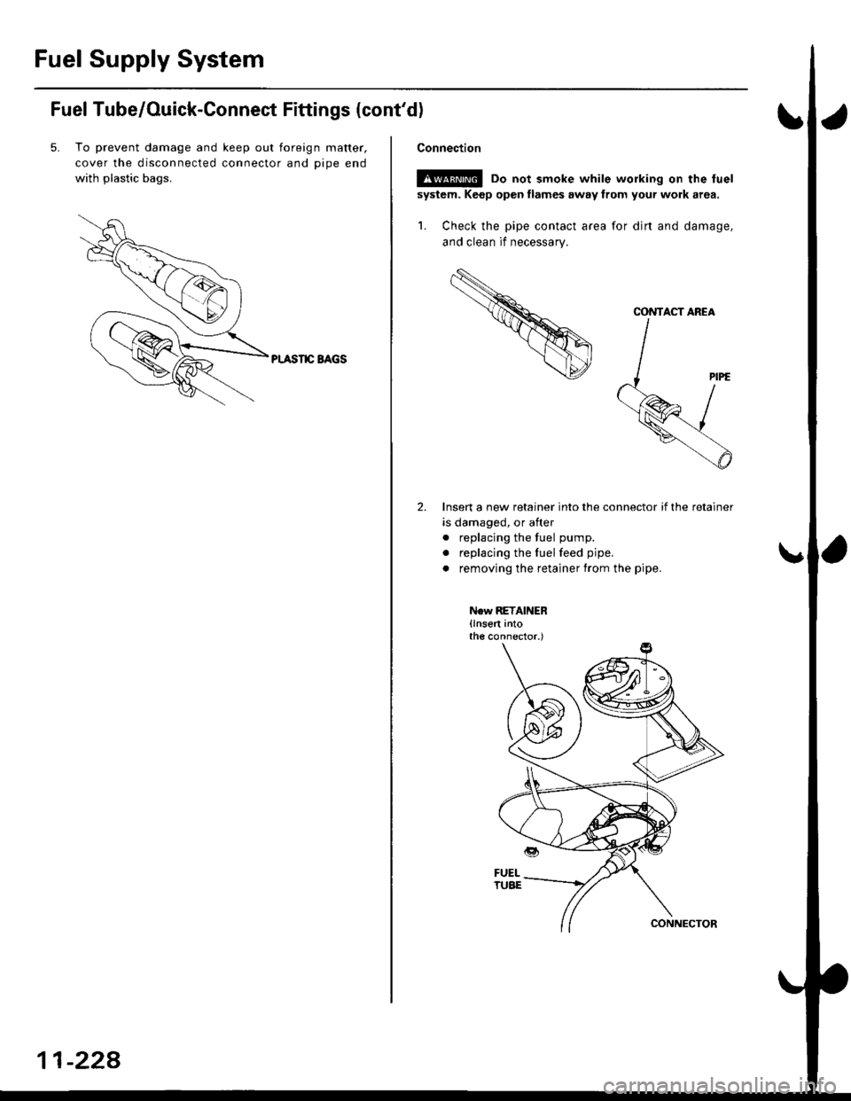
5. To prevent damage and keep out toreign matter,
cover the disconnected connector and oioe end
with plastic bags.
PI.ASIIC BAGS
11-228
Connection
!s@ Do not smoke while working on the fuel
system. Keep open llames away from your work area.
1. Check the pipe contact area for djrt and damage,
and clean if necessary,
Insert a new retainer into the connector if the retainer
is damaged, or after
. replacing the fuel pump.
. replacing the fuelfeed pipe.
. removing the retainer from the pipe.
N.w RETAINER(lnsert intothe connector.)
CONTACT AREA
Page 1121 of 2189

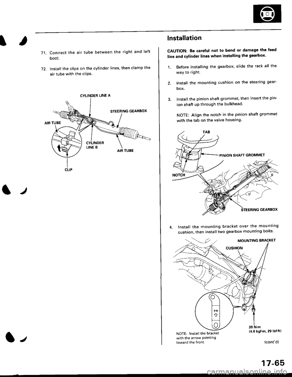
71.Connect the air tube between the right and left
boot.
lnstall the clips on the cylinder lines' then clamp the
air tube with the cliPs.
l./
CYLINDER LINE A
CLIP
l-,
lnstallation
CAUTION: Be carelul not to bend or damage the feed
line and cylinder lines when installing the gearbox'
1, Before installing the gearbox, slide the rack all the
way to right.
2. Install the mounting cushion on the steering gear-
DOX.
Install the pinion shaft grommet, then insert the pin-
ion shaft up through the bulkhead.
NOTE: Align the notch in the pinion shaft grommet
with the tab on the valve housing.
Install the mounting bracket over the mounttng
cushion, then installtwo gearbox mounting bolts'
MOUNTING BRACKET
cusHroN
39 N.m(4.0 kgj m, 29 lbtftlNOTE: Install the bracket
with the arrow Pornllngtoward the front.(cont'd)
17-65
Page 1122 of 2189

Steering Gearbox
Installation (cont'dl
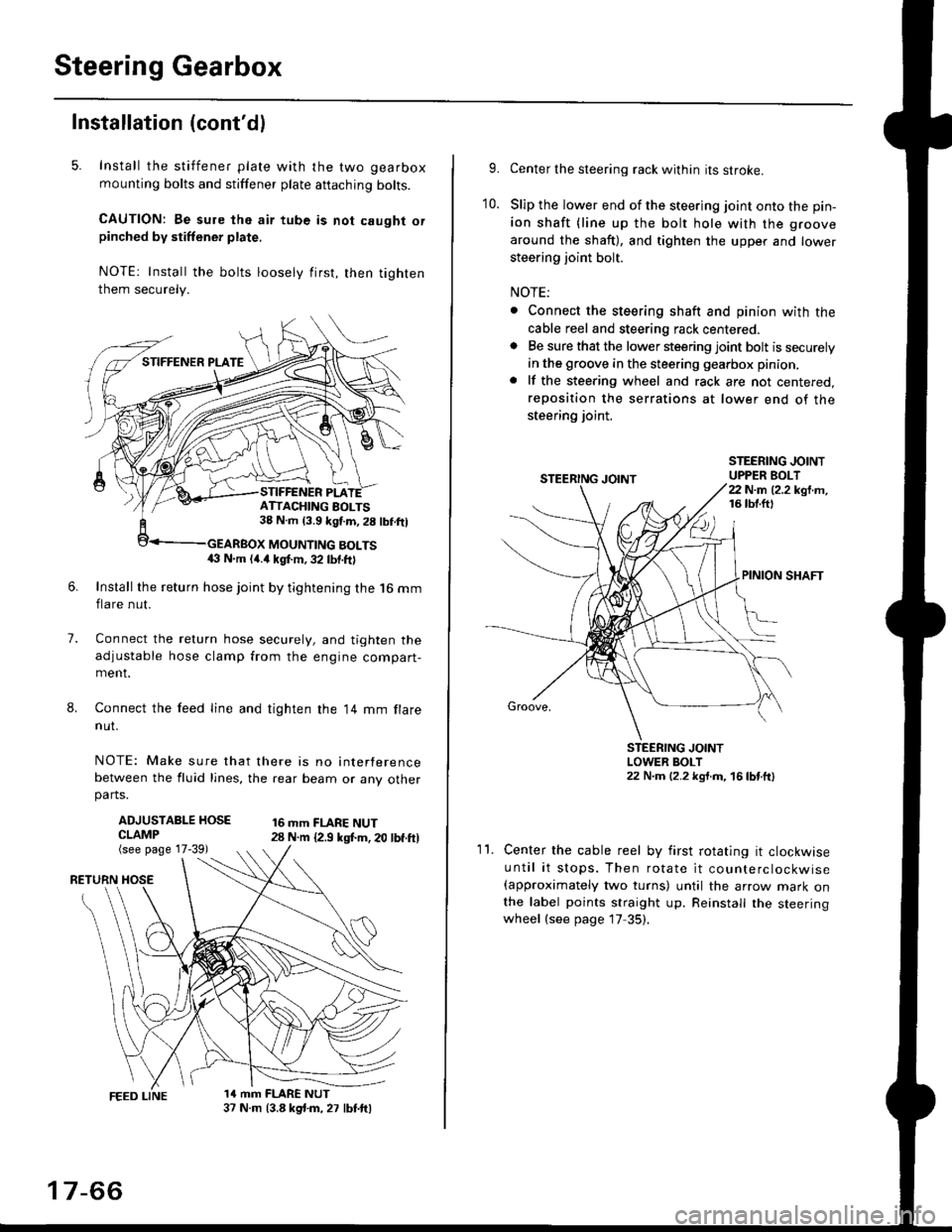
5. Install the stiffener plate with the two gearbox
mounting bolts and stiffener plate aftaching bolts.
CAUTION: Be sure the air tube is not caught orpinched by stiffener plate,
NOTE: Install the bolts loosely first, then tighten
them securely.
7.
8.
6.Install the return hose joint by tightening the l6 mm
flare nut.
Connect the relurn hose securely, and tighten the
adjustable hose clamp from the engine compart-ment.
Connect the feed line and tighten the 14 mm flare
nut.
NOTE: Make sure that there is no interference
between the fluid lines, the rear beam or any otherparts.
ADJUSTABLE HOSECLAMP(see page 17-39)
16 mm FLARE NUT28 N.m {2.9 ksl.m. 20 lbf.ft)
RETURN
1a mm FLARE NUT37 N.m (3.8 kg{.m, 27 lbt.ftl
ATTACHING AOLTS38 N.m 13.9 kgf.m, 28 lbf.ftl
MOUNTING BOLTS(} N.m (4.a kgt m, 32 lbf.ftl
17-66
9.Center the steering rack within its stroke.
Slip the lower end of the steering joint onto the pin-
ion shaft (line up the bolt hole with the groove
around the shaft), and tighten the upper and lower
steering joint bolt.
NOTE:
. Connect the steering shaft and pinion with the
cable reel and steering rack centered.. Be sure that the lower steering joint bolt is securely
in the groove in the steering gearbox pinion.
. lf the steering wheel and rack are not centered,
reposition the serrations at lower end of the
steering joint.
10.
STEERING JOINTUPPER BOLT22 N.m (2.2 kgf.m,16 tbt.ftl
PINION SHAFT
Groove,
STEERING JOINTLOWER BOLT22 N.m (2.2 kgt.m, 16lbtttl
11.Center the cable reel by first rotating it clockwise
until it stops. Then rotate it counterclockwise(approximately two turns) until the arrow mark onthe label points straight up. Reinstall the steeringwheel (see page 17 35).