Page 1348 of 2189
Emblems
Installation
Apply the emblems where shown.
NOTE:
. Before applying, clean the body surface with a sponge dampened in alcohol.
. After cleaning, keep oil, grease and water from getting on the surface.
Aftachment Points (Reterence):
CIVIC EMBLEM
Unit: mm (in.)
CIVIC emblem
TFUNK LID
CIVIC emblem
TRUNK LID
Vorsion emblemVersion emblemVersion emblsm
20-114
Page 1369 of 2189
Emblems
Installation
Align the application tape with the taillight and body, as shown, then press the emblem into place. Remove the appticationtape.
NOTE:
o Before applying, clean the body surface with a sponge dampened in alcohol.. After cleaning, keep oil, grease and water from getting on the surface.. When applying, make sure there are no wrinkles in the emblem.
Attschment Point:
VERSION EMBLEM
20-140
DOHC VTEC aid€ omblom:Vsrsion emblem:
Page 1373 of 2189
Emblem
Installation
Apply the emblem where shown.
NOTE:
. Before applying, clean the body surface with a sponge dampened in alcohol.. After cleaning, keep oil, grease and water from getting on the surface.
Attachment Point (ReferencG):Unit: mm (in,)
CIVIC EMBLEM
Special EMBLEM
20-144
3D: Special emblem {for Canada Sosciel Editionl
Page 1445 of 2189
A/C ThermostatRelays
Test
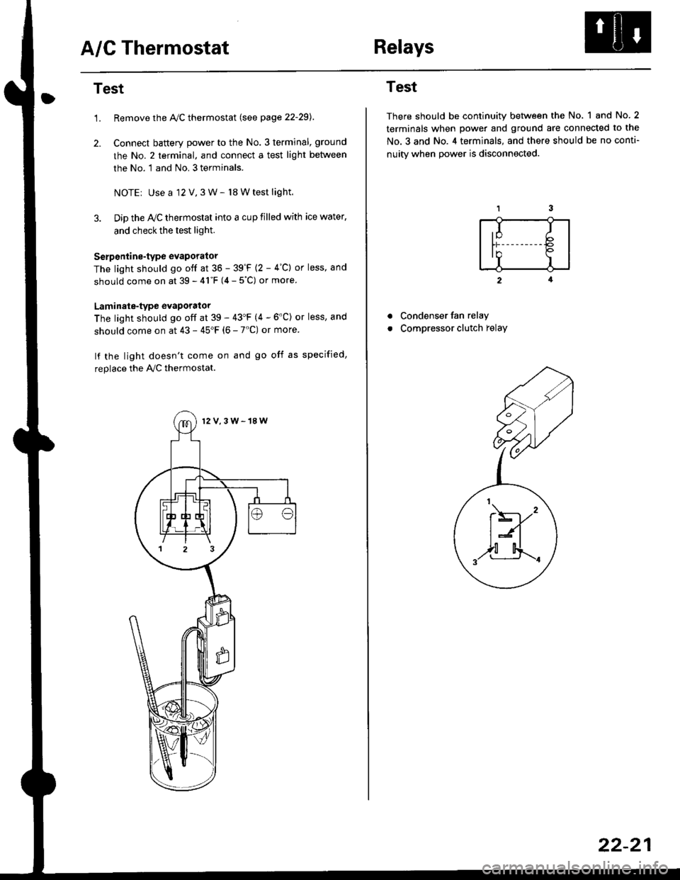
1.Remove the Ay'C thermostat (see page 22-29).
Connect baftery power to the No. 3 terminal, ground
the No. 2 terminal, and connect a test light between
the No. 1 and No. 3 terminals.
NOTEr Use a 12 V,3 W- l8 W test light.
Dip the IVC thermostat into a cup filled with ice water,
and check the test light.
Serp6ntine-type evaporator
The light should go off at 36 - 39'F {2 - 4"C} or less, and
should come on at 39 - 41"F (4 - 5"C) or more
Laminale-type evaporator
The light should go off at 39 - 43'F (4 - 6'C) or less, and
should come on at 43 - 45"F (6 - 7'C) or more
lf the light doesn't come on and go off as specified,
replace the PVC thermostat.
12V,3W-18W
Test
There should be continuity between the No, 1 and No.2
terminals when power and ground are connected to the
No.3 and No. 4 terminals, and there should be no conti-
nuitv when Dower is disconnected.
2
Condenser fan relay
Compressor clutch relay
a
a
,I Ib
In Io'r I
t\----,'
t:n
,,l[4..-.
22-21
Page 1450 of 2189
A/C System Service
Pressure Test Chart
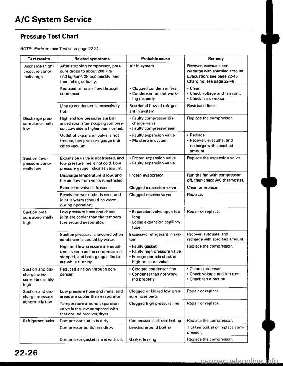
NOTE: Performance Test is on page 22-24,
Test resultsRelated symptomsProbabl€ causeRemedy
Discharge (high)
pressure aDnor-
mally high
After stopping compressor. pres-
sure drops to about 200 kPa
{2.0 kgflcm,,28 psi) quickly, and
then falls gradually.
Air in systemRecover, evacuate, and
recharge with specified amount.
Evacuation: see page 22-45
Charging: see page 22-46
Reduced or no air flow through
condenser
. Clogged condenser fins. Condenser fan not work-
ing properly
Clean.
Check voltage and fan rpm.
Check fan direction.
Line to condenser is excessively
hot.
Restricted flow of refriger-
ant in system
Restricted lines
Discharge pres-
sure abnormally
High and low pressures are bal-
anced soon after stopping compres-
sor, Low side is higher than normal.
. Faulty compressor dis-
charge valve. Faulty compressor seal
Replace the compressor.
Outlet of expansion valve is not
frosted, low pressure gauge indi-
cales vacuum.
. Faulty expansion valve. Moisture in system
. Replace,. Recover, evacuate, and
recharge with specified
amount.
Suction (low)
pressure abnor-
mally low
Expansion valve is not frosted, and
low oressure line is not cold. Low
pressure gauge indicates vacuum.
. Frozen expansion valve. Faulty expansion valve
ReDlace the exoansion valve.
Discharge temperature is low. and
the air flow from vents is restricted.
Frozen evaporatorRun the fan with compressor
off. then check A,/C thermostat.
Exoansion valve is frosted.Clogged expansion valveClean or replace.
Receiver/dryer outlet is cool, and
inlet is warm (should be warm
during operation).
Clogged receiver/dryerReplace.
Suction pres-
sure abnormally
hig h
Low pressure hose and check
joint are cooler than the tempera-
ture around evaporator.
. Expansion valve open too
long. Loose expansion capillary
tube
Repair or replace.
Suction oressure is lowered when
condenser is cooled bv water.
Excessive refrigerant in sys-
tem
Recover. evacuate, and
recharge with specified amount.
High and low pressure are equal-
ized as soon as the compressor is
stopped, and both gauges fluctu-
ate while running.
Faulty gasket
Faulty high pressure valve
Foreign particle stuck in
high pressure valve
Replace the compressor.
Suction and dis-
charge pres-
sures abnormally
h igh
Reduced air flow through con-
denser.
. Clogged condenser fins. Condenser fan not work-
ing properly
Clean condenser.
Check voltage and fan rpm.
Check fan direction.
Suction and dis-
charge pressure
abnormally low
Low pressure hose and metal end
areas are cooler than evaporator.
Clogged or kinked low pres-
sure hose parts
Repair or replace.
Temperature around expansion
valve is too low compared with
that around receiver/dryer.
Clogged high pressure lineRepair or replace.
Refrigerant leaksCompressor clutch is diny,Compressor shaft seal leakingReplace the compressor.
Compressor bolt{s) are diny.Leaking around bolt(s)Tighten bolt(s) or replace com-
pressor.
Compressor gasket is wet with oil.Gasket leakingReplace the compressor.
22-26
Page 1473 of 2189
Troubleshooting
ll.
Tips and Precautions
Bef ore Troubleshooting
. Check applicable fuses in the appropriate fuse/relay
box.
. Check the battery for damage, state of charge, and
clean and tight connections.
. Check the alternator belt tension.
CAUTION:
. Do not quick-charge a battery unless the battery
ground cable has been disconneqted, otherwise you
will damage the alternator diodes.
. Do not attempt to crank the engine with the battery
ground cable loosely connecled or you will severely
damage the wiling,
Handling Connectois
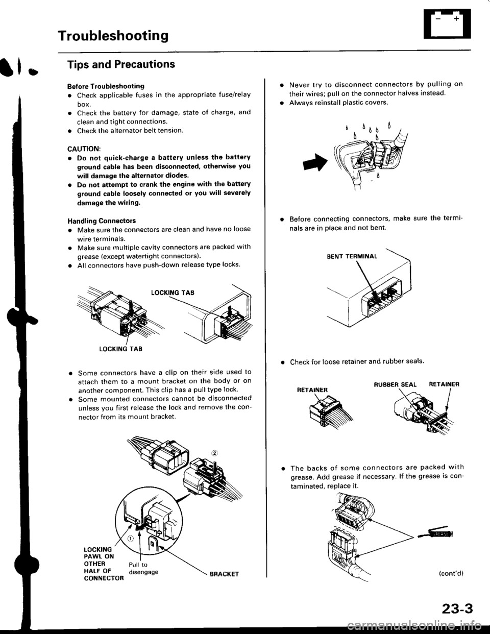
. Make sure the connectors are clean and have no loose
wire terminals.
. Make sure multiple cavity connectors are packed with
grease (except watertight connectors)
. All connectors have push-down release type locks.
Some connectors have a clip on their side used to
attach them to a mount bracket on the body or on
another component. This clip has a pulltype lock.
Some mounted connectors cannot be disconnected
unless you first release the lock and remove the con-
nector from its mount bracket.
LOCKINGPAWL ONOTHERHALF OFCONNECTOR
Pull todrsengage
LOCKING TAB
BRACKET
Never try to disconnect connectors by pulling on
their wires; pull on the connector halves instead
Alwavs reinstall plastic covers.
Before connectang connectors,
nals are in place and not bent.
make sure the terml-
. Check for loose retainer and rubber seals.
RETAINER
The backs of some connectors are packed with
grease. Add grease if necessary. lf the grease is con-
taminated, replace it.
(cont'd)
23-3
Page 1474 of 2189
Troubleshooting
Tips and Precautions (cont'dl
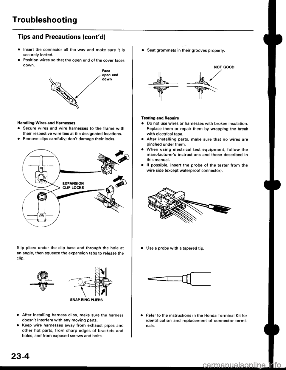
Insert the connector all the way and make sure it is
securelv locked.
Position wires so that the open end of the cover faces
down.
After installing harness clips, make sure the harness
doesn't interfere with any moving pans.
Keep wire harnesses away from exhaust pipes and
other hot parts. from sharp edges of brackets and
holes, and from exDosed screws and bolts.
V
F6c6op€n end
Handling Wires and Harnosscs
. Secure wires and wire harnesses to the frame with
their respective wire ties at the designated locations,
. Remove clips carefully; don't damage their locks.
Slip pliers under the clip base and through the hole at
an angle, then squeeze the expansion tabs to release the
clrp.
SNAP-BING PLIERS
23-4
NOT GOOO
ll il,/
s*' -.1}8."/_Y--_Y5\
il ,,
Testing and Repairs
o Do not use wires or harnesses with broken insulation.
Replace them or repair them by wrspping the break
with electricaltaoe.
. After installing parts, make sure that no wires arepinched under them.. When using electrical test equipment, follow the
manufacturer's instructions and those described in
this manual.
. lf possible, insert the probe of the tester from the
wire side (except waterproof connector).
. Seat grommets in their grooves properly.
. Use a probe with a tapered tip.
Refer to the instructions in the Honda Terminal Kit for
identification and replacement of connector termi-
nats.
Page 1561 of 2189
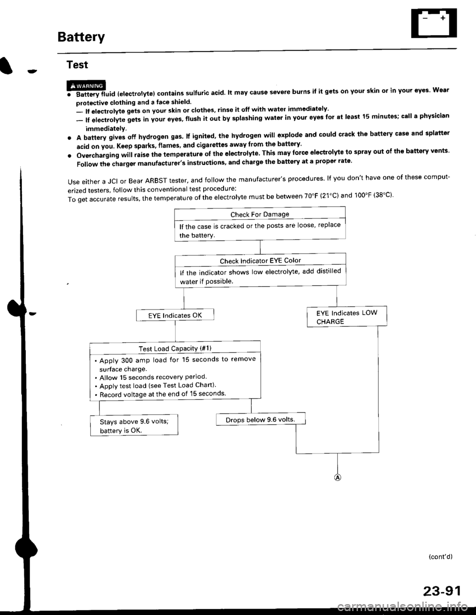
Battery
Test
@l. Battery lluid lelectrolytel contalns sulfuric acid. lt may cause severe burns it it gets on your skin ol in your eyes Wear
protective clothing and a face shield.
- It eleqtlolyte gets on your skin or clothes, rinse it off with watel immediately
- lf electrolyte gets in your eyes, flush it out by splashing water in your eyes for at least 15 minutes; call a physician
immediately.
. A battery gives off hydrogen gas. lf ignited, the hydrogen will explode and could crack the battery case and splatter
acid on you. Keep sparks, flames, and Gigarettes away from the battery'
o Overchaiging will raise the temperature oI the electrolyte. This may force electrolyte to spray out ot ths battery vents'
Follow the charger manufacturel's instrustions, and chalge the battery at a propcr rate.
Use either a JCI or Bear ARBST tester. and follow the manufacturer's procedures. lf you don't have one of these comput-
erized testers, follow this conventional test procedure:
ToqetaccurateresuIts,thetemperatureoftheeIectro|ytemustbebetweenT0"F(21.c)and100"F(38.c}'
lf the case is cracked or the posts are loose, replace
the battery.
lf rhe indicator shows low electrolyte, add distilled
water if Possible.
EYE lndicates OK
Test Load CaPacitY (#l )
. Apply 300 amp load for 15 seconds to remove
surface charge.. Allow 15 seconds recovery Perloo.. Apply test load {see Test Load Chan).
. Record voltage at the end of l5 seconds.
Drops below 9.6 volts.Stays above 9.6 volts;
battery is OK.
(cont'd)
23-91