Page 745 of 2189
From page 14-66
Check Shift Conlrol Sol€noidvalve B tor a Short Circuit:1. Disconnect the 2P connectortrom the shift control solenoidvalve assembly.2. Check for continuity betweenthe 811 and Ag or A22 termi-nals,
Replir shon to ground in th€ wirebetwe.n the 811 terminal and the3hift control solenord valvo B.ls there continuity?
Measure Shift Control Solenoidvrlve B Resistance at the Sole-noid Connector:Measure the resistance betweenthe No.2 terminalofthe shift control solenoid connector and bodyground.
Check tor ooen in the wirebetw..n thc 81 1 t€tminal ard thashift control solonoid vrlv6 B.ls the resistance 12 25 O?
, 2 ll r . 5
PCM CONNECTORS
Wire side of female terminals
SHIFT CONTROL SOLENOID
CONNECTOR
GRN/WHT
Terminal side ol male terminals
14-67
Page 746 of 2189

Electrical Troubleshooting ('gO - 98 Modelsl
Troubleshooting Flowchart - Countershaft Speed Sensor
Po$iblo Causa
' Loosg or laulty conncctionbotwocn tho PCM and c.i hrr-n1't!' Disconnoctad countorahottlpo€{ san3or oonnoctot. Short or opon in countorshaftspeed lonsor wire. F ulty counte.lhalt spe6d s6n-sol
COUNTERSHAFT SPEED SENSORCONNECTOR
lFI,]1-F=r
9l
L_l
Terminal side ol male terminals
PCM CONNECTOR B I25P}
1
l'
NOTE; Record allfreeze data before you troubleshoot.
. OBO ll Scln Tool indicat6 Codem7z).. S6lt-dirgnosis E indic.tollight blink! nin. tim6,
ls the countershaft spoed sensorinstalled properly?
Moa3ure CountoEhaft Sp€ed S6n-sor Reaktanc€ at tho Son3or Con-noctor1. Disconnect the 2P connectortrom the countershaft spgedsensor connector,2. Measure the resistance of thecountershaft sDeed sensor,
ls the resistance 400 - 600 0?
Chock Countersh.ft Spood Scr|3olfor a Shoft Circuit:1. Disconnect the B {25P) connector from the PCM.2. Check for continuity betweenthe body ground and the 823terminal and 822 terminalindividually.
Repai. .hort in th. wiroa b.t$re€ntho 823 lnd 822 torminals .ndlho counteBhaft lpocd aenro..
To page 14-69
4-68
Wire side of temale terminals
Page 748 of 2189

Electrical Troubleshooting ('96 - 98 Modelsl
Troubleshooting Flowchart - Mainshaft Speed Sensor
NOTE: Record all freeze data before you troubleshoot.
Po$ible Cause
. Disconnect€d mainshaft sD€edSensor @nnoctot. Short or open in mainshattsJt€ed s6nsoa wire. Faulty mainshaft lpeed s6nso.
NOTE: Code P0715 (15) on the PCMdoesn't always mean there's an electricalproblem in the mainshaft or countershaftspeed sensor circuit; code P0715 (15)may also indicate a mechanical problemin the transmission.
MAINSHAFT SPEEOSENSOR CONNECTOR
Terminal side of male terminals
PCM CONNECTOR B I25PI
. OBD ll Scan Tool indicates Codem715.. Self-dirgnosi3 E indicatorlight indicstes Code 15.
Check the mainshaft and counter-shaft speed sensor installation.
Are the mainshaft and countershaftspeed sensor installed properly?
Moasure Mainshaft Spoed SgnsolRosistance at the Sensor Con-n€ctor:1. Disconnect the 2P connectorfrom the mainshaft speed sen-sor connector.2. Measure the resistance ot themainshaft speed sensor.
ls the resistance 400 600 O?
Check Mainshaft Sp6ed Sensorfor a Short Circuil:1. Disconnect the B {25P) connec'tor lrom the PCM.2. Check for continuity betweenbody ground and 815 terminaland the 814 terminal individu,
Repai. shon in the wi.os bstwoenthe 815 and 814 te.minals andthe mainshatt .Dood 3ensor.
ls there continuity?
To page 14-71
14-70
Wire side of female terminals
Page 750 of 2189

Electrical Troubleshooting ('96 - 98 Modelsl
Troubleshooting Flowchart - Linear Solenoid
NOTE: Record all freeze data before vou troubleshoot,
Po$ible Caus6
. Disconnoctod lineaJ solonoidconnectot. Short or open in linoar solenoid
' Faulty linoar solonoidLINEAR
Terminal side ol male terminals
PCM CONNECTOR B I25PI
Wire side of female terminals
SOLENOID CONNECTOR
l;r]l
TT
YI
LI
REDWHT
OBO ll Scan Tool indicates CodeP176a.Self-diagnosi3 E indicatorlight indicates Code 16,
Measure Linear Solenoid Resist-ance at the Solenoid Connecto.:1. Turn the ignition switch OFF.2. Disconnect the 2P connectorlrom the linear solenoid connector,3. Measure the resistance ofthelinear solenoid.
ls the resistance approx. 5.0 O?
Check Linear Solenoid for a ShonCircuit:1. Disconnect the B 125P) connec-tor from the PCM.2. Check for continuity betweenthe body ground and the B1terminal and 82 terminal inda-vidually.
Repair short in the wires bgtwoenthe Bl and 82 terminab and thelineti solsnoid.
Meaaure Linoar Solenoid RGi3t-anc€:1. Connect the linear solenoidconnector.2, Meas u re the resistancebetween the 81 and 82 termi-nals,
Ropair looso terminal or open inthe wires botwe€n the 81 and 82telminals end the linear solenoid.
ls the resistance approx. 5.0 O?
To page 14-73
14-72
Page 756 of 2189
Electrical Troubleshooting ('96 - 98 Models)
Th6 E indicstor light is on con-st.ntly {not blinkingl wheneveithe ignition switch is ON lll).
Measure 04 IND Voltage:1. Turn the ignition switch OFF.2. Disconnect the B 125P) connec-tor from the PCM.3. Turn the ignition switch ON (ll).
4. Measure the voltage betweenthe 813 terminal and bodyground,
Repair 3hort to pow€. in the wirobetween the 813 terminal endthc gauge asiombly.
Meaiure ATP Dil Voltage:1. Turn the ignition switch OFF.2. Connect the I (25P) connectorto the PCM.3. Turn the ignition switch ON (ll).4. Shiftto any position otherthan
5. Measure the voltage betweenthe 824 terminal and bodygrou nd.
Check for a short to ground on thowir6. It wire i3 OK, .eplac6 the A/Tgoar po3ition indbator,
Troubleshooting Flowchart - E Indicator Light On Constantly
a!
PCM CONNECTOR B (25P)
Wire side of lemale terminals
l.
14-7A
Page 761 of 2189

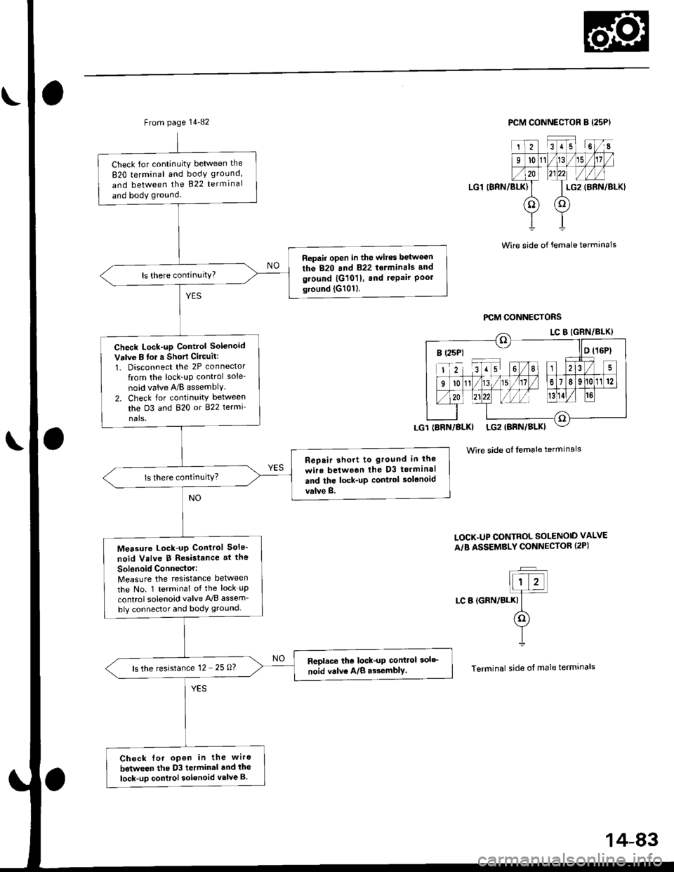
From page 14-82
Check for continuitY between the
820 terminal and body ground,
and between the 822 terminal
and body ground
Repair open in the wires between
the 820 and 822 terminals and
ground |G101), and repair Poolground (G1011.
Check Lock-up Control Solenoid
Valve B lor a Short Cilcuit:
1. Disconnect the 2P connector
from the lock_uP control sole-
noid vaive A/B assemblY.
2. Check for continuity between
the D3 and 820 or 822 termi
nals.
Rep.ir short to ground in lho
wire between lhe D3 terminal
and the lock-up contlol solenoid
valve B.
Measure Lock-up Control Sol6'
noid Valve B Resistance at the
Sol6noid Conn€ctor:Measure the resistance between
the No. 1 terminal of the lock uP
control solenoid valve A'lB assem_
bly connector and body ground-
Repl.ce the lock-up control 3olc
noid valve A/B a$emblY.ls the resistance 12 - 25 0?
Ch6ck {or open in the wire
between the D3 terminal dnd ihe
lock-up control sol€noid valve B.
PCM CONNECTOR B (25PI
LG1 (BRN/BLK)
2351 6I
l011/15
LG2
oo
(BRN/BLKI
Wire side of female terminals
Wire side of female terminals
LOCK.UP CONTROL SOLENOID VALVE
A/B ASSEMBLY CONNECTOR (2PI
t;T�Jllt z!]4
LC B (GRN/BLKI It(o)
YI
Terminal side of male termrnals
B (25P1 - llo t16Pt
14-83
Page 762 of 2189

Electrical Troubleshooting ('gg - 00 Models)
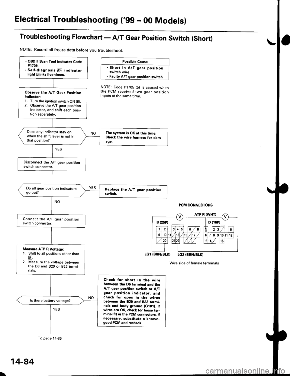
Troubleshooting Flowchart - A/T Gear position Switch (Short)
NOTE: Record all freeze data before you troubleshoot.
Po$ible Cause
' Short in A/T go.r positionswhch wire. Faulty A/T goar position switch
NOTE: Code P1705 (5)the PCM received twoinputs at the same time.
is caused whengear position
PCM CONNECTORS
LGl (BRN/BLK) LG2 (BRN/BLKI
Wire side of femaleterminals
B {25P1 llD (16P1
. OBD ll Scan Tool indicrtB CodeP1?05.. Solt-diagno3i3 E indicatorlight blink. tive times.
Observo the A/T Gear PositionIndicetori1. Turn the ignition switch ON fit).2. Observe the lVT gear positionindicator, and shift each posi,!on separately.
Does any indicator stay onwhen the shift lever is not inthat position?
The sFtom is OK at thi3 time.Check the wi.e harness for dam-aga.
Do all gear position indicatorsgo out?
Moasure ATP R Voltage:1. Shift to all positions otherthanE.2. Measure the voltage betweenthe DG and 82O o( 822 terfii-nats.
Check tor short in the wirebatwoen tha DB terminal and theA/T go.r porhion switch or A/Tg6ar po3ition indicator, andchock for opon in the wiresbetween the B20 and B22 t€rmi-n.ls and body ground (G10 . tfwir€c rro OK, chsck fo. loo3e tel-ftinal fit in the FCM connectors. llnoceisary, substiiute e known-good FCM and r€check.
ls there battery voltage?
To page 14-85
\
14-84
Page 768 of 2189

Electrical Troubleshooting ('gg - 00 Models)
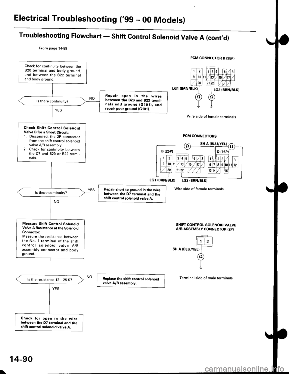
Troubleshooting Flowchart - Shift Control Solenoid Valve A (cont,O)
PCM CONNECTOR B {25P}
LGl (BRN/BLKI
Wire side of female terminals
rcM CONNECTORS
LGl {BBN/BLKI LG2 (BRN/BLKI
Wire side of female terminals
SHIFT CONTROL SO|'INOID VALVEA/B ASSEMBLY CONNECTOR I2PI
SH A {BLU/YELI
From page 14-89
Check lor continuity between the820 terminal and body ground,and between the 822 terminaland body ground.
Repair open in ihe wiresbetween th€ 820 and 822 termi-nals end ground {G10ll. andrepa,r poor ground {G101}.
Check Shitt Control SolenoidValve B for a Short Circuit:1. Disconnect the 2P connectorfrom the shilt control solenoidvalve A,/B assembly.2. Check lor continuity betweenthe D7 and 820 or 822 termi,nals.
R€pair short to ground in the wiiebartwe€n the D7 te.minal and theshift control solonoid valve A.
ls there continuity?
Meesuro Shift Control SolenoidValve A RGistance at the SolenoidConnector:Measure the resistance betweenthe No. 1 terminal of the shiftcontro I solenoid valve A/Bassembty connector and bodygrounct,
Repl.ce tho shift control solenoidvalve A/B rss€mblv.ls the resistance 12 25 O?
Check for open in the wirebetween the D7 termindl and theshift control 3olonoid valve A.
B t25Pt llD t16Pt
\
14-90