1998 HONDA CIVIC MAIN WIRE
[x] Cancel search: MAIN WIREPage 1662 of 2189
Stereo Sound System
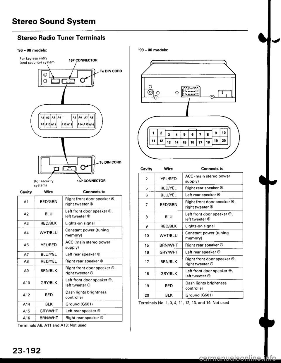
Stereo Radio Tuner Terminals
'96 - 98 models:
For keyless entry . t6p coNNEcroR(and securrty) syslem
To DIN CORD
To DIN CORD
(for securitysystem)
Cavity Wire
A1RED/GRNRight front door speaker o,
right tweeter @
BLULeft front door speaker @,
left tweeter @
A3RE D/B LKLights-on signal
A4WHT/BLUConstant power (tuning
memoryl
A5YEL/REDACC (main stereo power
suppry)
A7BLUI/ELLeft rear speaker O
A8RE DI/E LRight rear speaker O
A9BRN/BLKRight front door speaker O,
right tweeter o
A10GRY/BLKLeft tront door speaker O,
left tweeter O
412REDDash lights brightness
controller
A14BLKGround (G501)
415GRYMHTLeft rear speaker O
Al6BR N/VVHTRight rear speaker O
Terminals A6, A11 and A13: Not used
23-192
'99 - 00 models:
CsvityConnccts toWire
2YEL/REDACC (main stereo power
suppry)
5RE DI/E LRight rear speaker @
BLUI/ELLeft rear speaker @
7RED/GRNRight front door speaker @,
right tweeter @
8BLULeft front door speaker @,
left tweeter @
9RED/BLKLights-on signal
10WHT/BLUConstant power (tuning
memory)
15BRN,ryVHTRight rear speaker O
GRYMHTLeft rear speaker O
17BRN/BLKRight front door speaker O,
right tweeter O
18G RY/BLKLeft front door speaker O,
left tweeter O
'19REDDash lights brightness
controller
20BLKurouno t(l5u t,
Terminals No. 1, 3, 4, 11,12, 13, and 14: Not used
Page 1669 of 2189
Switch Test
lMake sure you have the anti-theft code for the
radio, then write down the frequencies for the
radio's preset buttons ('99 - 00 models).
Disconnect the battery negative cable, then disconnect
the positive cable, and wait at least three minutes.
Disconnect the driver's airbag connector (see sec-
tion 24).
Remove the driver's dashboard lower cover (see
section 20).
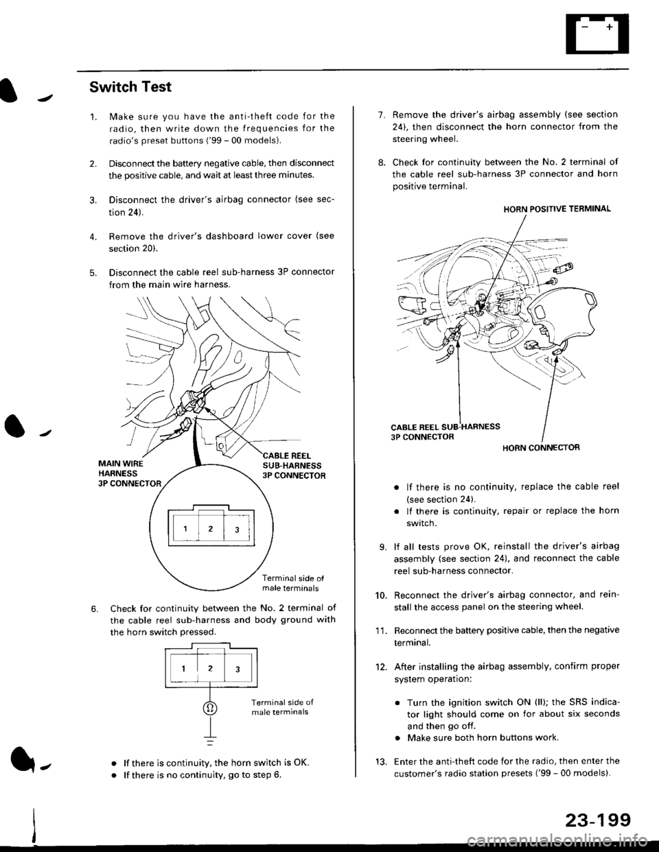
Disconnect the cable reel sub-harness 3P connector
from the main wire harness.
2.
3.
4.
5.
1.
MAIN WIREHARNESS3P CONNECTOR
SUB-HABNESS3P CONNECTOR
REEL
6.
Terminalside olmale terminals
Check for continuity between the No. 2 terminal of
the cable reel sub-harness and body ground with
the horn switch pressed.
alf there is continuity, the horn switch is OK.
lf there is no continuity, go to step 6l-
-\
1.
8.
10.
'I 1.
9.
Remove the driver's airbag assembly (see section
24), then disconnect the horn connector from the
steering wheel.
Check for continuity between the No. 2 terminal of
the cable reel sub-harness 3P connector and horn
positive terminal.
lf there is no continuity, replace the cable reel
(see section 24).
lf there is continuity, repair or replace the horn
swtlcn,
lf all tests prove OK, reinstall the driver's airbag
assembly (see section 24), and reconnect the cable
reel sub-harness connector.
Reconnect the driver's airbag connector, and rein-
stall the access panel on the steering wheel.
Reconnect the battery positive cable, then the negative
termtnar.
After installing the airbag assembly, confirm proper
system operation:
12.
Turn the ignition switch ON (ll); the SRS indica-
tor light should come on for about six seconds
and then go off.
Make sure both horn buttons work.
13. Enter the anti-theft code for the radio, then enter the
customer's radio station presets ('99 - 00 models).
HORN CONNECTOR
23-199
Page 1713 of 2189
)
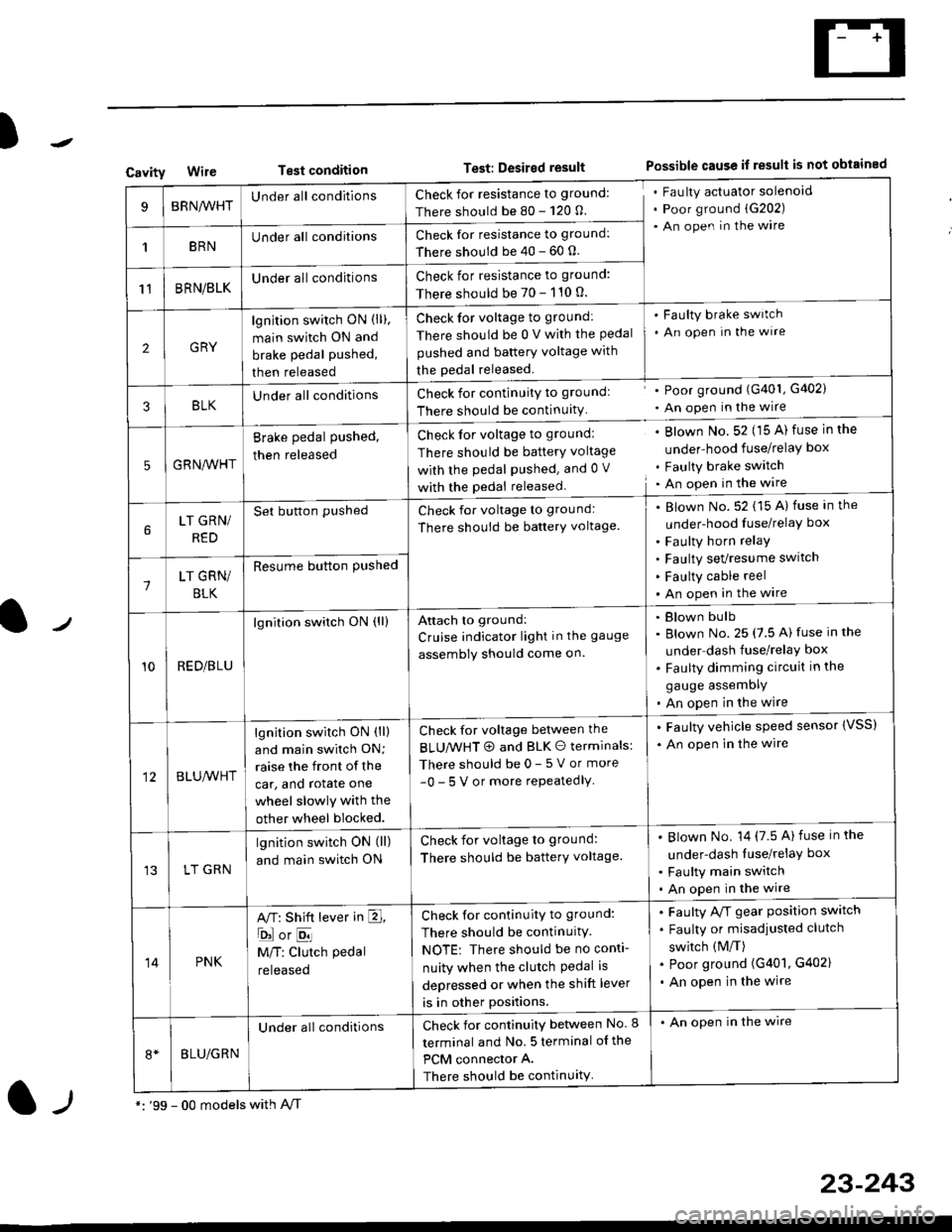
CavityWireTest conditionTest: Desired resultPossible cause if result is not obtained
BRNA/VHTUnder all conditionsCheck for resistance to ground:
There should be 80 - 120 O.
Fau lty actuator solenoid
Poor ground (G202)
An open in the wire
1BRNUnder all conditionsCheck for resistance to ground:
There should be 40 - 60 0.
11BRN/BLKUnder all conditionsCheck for resistance to ground:
There should be 70 - 110 0.
2GRY
lgn jtion switch ON (ll),
main switch ON and
brake pedal pushed,
then released
Check for voltage to ground:
There should be 0 V with the Pedal
pushed and battery voltage with
the pedal released.
'Faulty brake switch
. An open In the wlre
3BLKU nderall conditionsCheck for continuitY to groundl
There should be continuity
' Poor ground (G401, G402)
. An open in the wire
5GRNA,A/HT
Brake pedal pushed,
then released
Check for voltage to groundl
There should be batterY voltage
with the Pedal Pushed. and 0 V
with the pedal released
. Blown No. 52 (15 A) fuse in the
under-hood fuse/relaY box
. Faulty brake switch. An open in the wire
LT GRN/
RED
Set button pushedCheck for voltage to ground:
There should be batterY voltage.
Blown No. 52 (15 A) fuse in the
under-hood fuse/relaY box
Faulty horn relay
Faulty sevresume switch
Faulty cable reel
An open in the wire7LT GRN/
BLK
Resume button Pushed
10RED/BLU
lgnition switch ON (ll)Attach to ground:
Cruise indicator light in the gauge
assembly should come on.
Blown bulb
Blown No. 25 (7.5 A) fuse in the
under dash fuse/relay box
Faulty dimming circuit in the
gauge assemDly
An open in the wire
BLU,A/VHT
lgnition switch ON (ll)
and main swilch ON;
raise the front of the
car, and rotate one
wheel slowly with the
other wheel blocked.
Check for voltage between the
BLUMHT @ and BLK O terminals:
There should be 0- 5 V or more
-0- 5 V or more repeatedlY
. Faulty vehicle speed sensor {VSS)
. An open in the wire
LT GRN
lgnition switch ON (ll)
and main switch ON
Check for voltage to ground:
There should be batterY voltage.
Blown No. 14 (7.5 A)fuse in the
under-dash luse/relaY box
Faulty main switch
An open in the wire
14PNK
A,T: Shift lever in E,
ojorE
M/T: Clutch pedal
released
Check for continuity to ground:
There should be continuity.
NOTE: There should be no conti-
nuity when the clutch Pedal is
depressed or when the shift lever
is in other positions.
Faulty A/f gear position switch
Faulty or misadjusted clutch
switch (M/T)
Poor ground (G401, G402)
An open in the wire
BLU/GRN
Under all conditionsCheck for continuity between No. I
terminal and No. 5 terminal of the
PCM connector A.
There should be continuity
. An open in the wire
*: '99 - 00 models with A,/Tl-,
23-243
Page 1714 of 2189
Cruise Gontrol
3.
1.
2.
Main Switch Test/Replacement
Remove the driver's dashboard lower cover (see sec-tion 20).
Carefully push out the switch from behind the dashboard.
Disconnect the connector from the swtrcn.
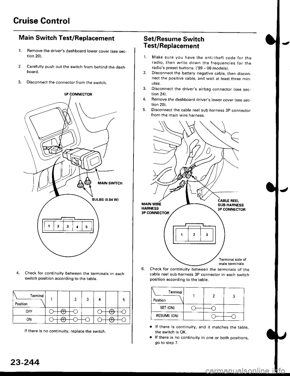
MAIN SWITCH
BULBS {0.84 Wt
Check for continuity between the terminals in eachswitch position according to the table.
lf there is no continuity. reDlace the switch.
4.
Terminal
r**
--\235
OFFo--oGa\-o\:./\a/
ONo-/a-oo--o\:/\:/
23-244
Set/Resume Switch
5.
Test/Replacement
2.
1.
MAIN WIREHARNESS3P CONNECTOR
Make sure you have the anti-theft code for theradio, then write down the frequencies for theradio's preset buttons. ('99 - 00 models).Disconnect the battery negative cable, then discon-nect the positive cable, and wait at least three min-utes.
Disconnect the driver's airbag connector (see sec-tion 24).
Remove the dashboard driver's lower cover (see sec,tion 20).
Disconnect the cable reel sub harness 3p connectorfrom the main wire harness.
CABLE BEELSUB-HARNESS3P CONNECTOS
Terminalside ofmale terminals
Check for continuity between the terminals of thecable reel sub-harness 3P connector in each switchposition according to the table.
L Terminal
Position123
SET (ON}o----o
BESUi,|E IONIo-----o
lf there is continuity, and it matches the table,the switch is OK.
lf there is no continuity in one or both positions,
go to step 7.
Page 1741 of 2189
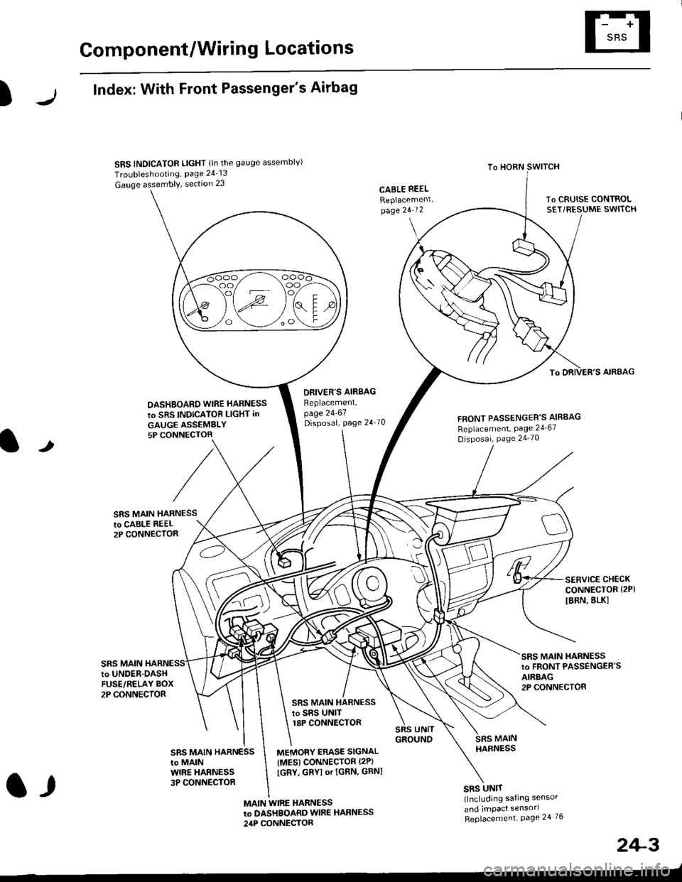
Component/Wiring Locations
)
Index: With Front Passenger's Airbag
SRS INDICATOR LIGHT (ln the gauge assemblvl
Troubleshooting, Page 24 13
Gauge assembly, section 23CABLE REEL
Replacemenlpage 2!-t 2
To HORN SWITCH
SRS UNIT(lncluding safing sensor
and imPact sensorl
Replacement Page 24 76
To DRIVER'S AIRBAG
DASHBOARD WIRE HARNESS
to SRS INDICATOB LIGHT in
GAUGE ASSEMBLY5P CONNECTOB
DBIVER'S AIRBAG
Beplacement,page 24-61Disposal, page 24 70FRONT PASSENGER'S AIBBAG
Replacement, Page 24_67
Disposal, Page 24 70
t
SRS MAIN HARNESSto CABI-E RE€L2P CONNECTOR
SRS MAIN
SERVICE CHECKCONNECTOR {2PI
IBRN, BLK]
to UNOER-OASHFUSE/RELAY BOX2P CONNECTOR
SRS MAIN HARNESSto FRONT PASSENGER'SAIRBAG2P CONNECTOB
SRS MAIN HARNESSto SRS UNITr8P CONNECTOR
SBS MAIN HARNESSto MAINWIRE HARNESS3P CONNECTOR
MEMORY ERASE SIGNAL(MES) CONNECTOR I2P)
[GRY, GRYI or IGRN. GRNI
MAIN WIRE HARNESSto DASHBOARD WIRE HARNESS
24P CONNECTOR
2+3
t,
Page 1742 of 2189
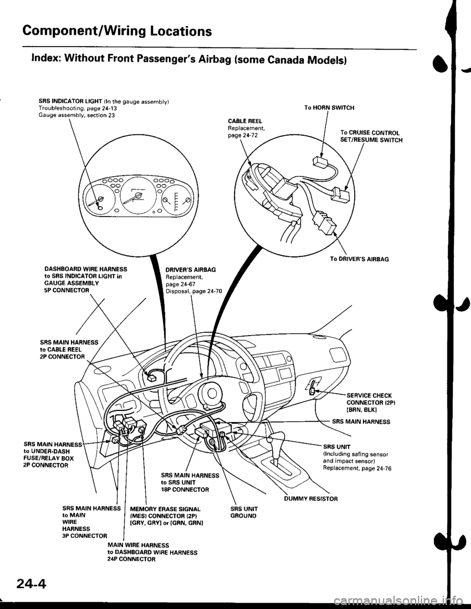
Gomponent/Wiring Locations
Index: Without Front Passenger's Airbag (some Canada Modelsl
SRS INDICATOR LIGHT (ln the gauge assembly)Troubleshooting, page 24-13Gauge assembly, section 23
DRIVER'S AIRSAGReplacement,page 24-67Disposal, page 24-70
SRS UNITGROUNO
To HORN SWITCH
SRS MAIN HARNESS
SRS UNIT{lncluding safing sensorand impact sensor)Replacement. page 24,76
To CRUISE CONTROLSET/RESUME SWITCH
oo/ \oo
To DRIVER,S AIRBAG
DASHBOARD WIRE HARNESSto SRS INDICATOR LIGHT inGAUGE ASSEMBLY5P CONNECTOR
SERVICE CHECKCONNECTOR {2P}IB8N, BLKI
SRS MAINto UNDER-DASHFUSE/RELAY BOX2P CONNECTOR
SRS MAIN HARNESSto SRS UNIT18P CONNECTOR
SRS MAIN HARNESSto MAINWIREHARNESS3P CONNECTOR
MEMORY ERASE SIGNAL(MES) CONNECTON (2P'
IGRY, GRYI o. IGRN, GRNI
MAIN WIRE HARNESSto DASHBOARD WIRE HARNESS24P CONNECTOR
24-4
DUMMY RESISTOB
Page 1751 of 2189
rl
Troubleshooting
t)
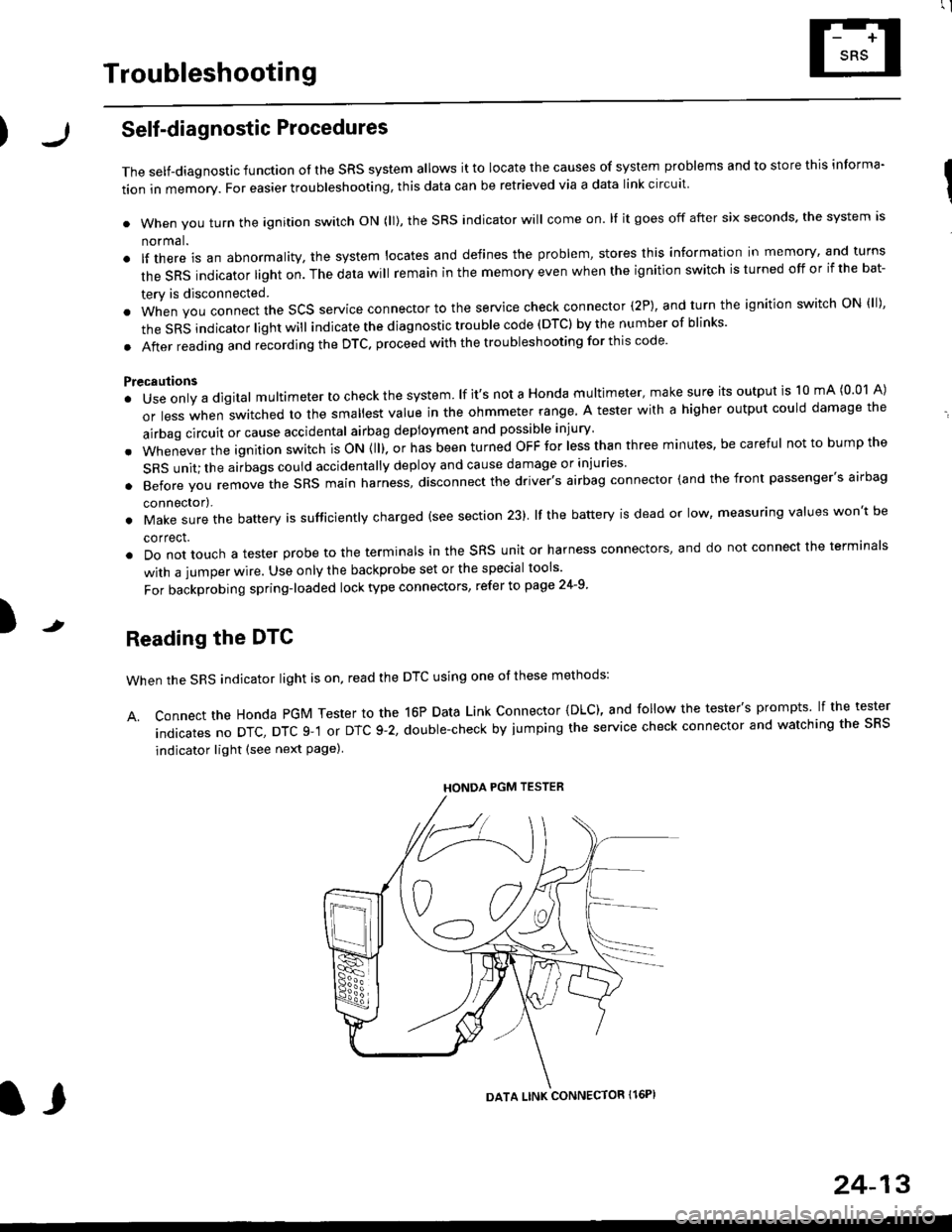
Self-diagnostic Procedures
The self-diagnostic function of the SRS system allows it to locate the causes of system problems and to store this informa' I
tion in memory. For easier troubleshooting, this data can be retrieved via a data link circuit l
. When you turn the ignition switch ON (ll), the SRS indicator will come on. ll it goes off after six seconds. the system is
norma l.
. lf there is an abnormality, the system locates and defines the problem, stores this information in memory, and turns
the sRS indicator light on. The data will remain in the memory even when the ignition switch is turned off or if the bat-
tery is disconnected.
o when you connect the scs service connector to the service check connector (2P), and turn the ignition switch oN (ll),
thesRsindicator|ightwi||indicatethediagnostictroub|ecode(DTC)bythenumberofb|inks.
. After reading and recording the DTC. proceed with the troubleshooting for this code'
Precauiions
.Useon|yadigita|mU|timetertocheckthesystem'|fit,snotaHondamu|timeter,makesureitsoutputisl0mA(0.01A)
or|esswhenSwitchedtothesma||estva|ueintheohmmeterrange,AtesterwithahigheroUtpUtcoulddamagethe��
airbag circuit or cause accidental airbag deployment and possible injury'
r when-ever the ignition switch is oN (ll). or has been turned oFF for lessthan three minutes, be careful nottobumpthe
SRS unit; the airbags could accidentally deploy and cause damage or injuries
. Before you ,"n1ou" th" SRS main harness, disconnect the driver's airbag connector (and the front passenger's airbag
connector).
. Make sure the battery is sufficiently charged {see section 23}. lf the battery is dead or low, measuring valLles won t be
correct.
. Do not touch a tester probe to the terminals in the sRS unit or harness connectors, and do not connect the terminals
with a jumper wire. Use only the backprobe set or the special tools'
For backprobing spring-loaded lock type connectors, refer to page 24-9'
Reading the DTC
when the SRS indicator light is on, read the DTC using one of these methods:
A. Connect the Honda PGM Tester to the 16P Data Link Connector {DLC), and follow the tester's prompts lf the tester
indicatesnoDTc,DTcg-1orDTc9-2,doub|e-checkbyjumpingtheservicecheckconnectorandwatchingthesRS
indicator light (see next Page)
HONDA PGM TESTER
DATA LINK CONNECTOR Il6PI
l,
24-13
Page 1763 of 2189
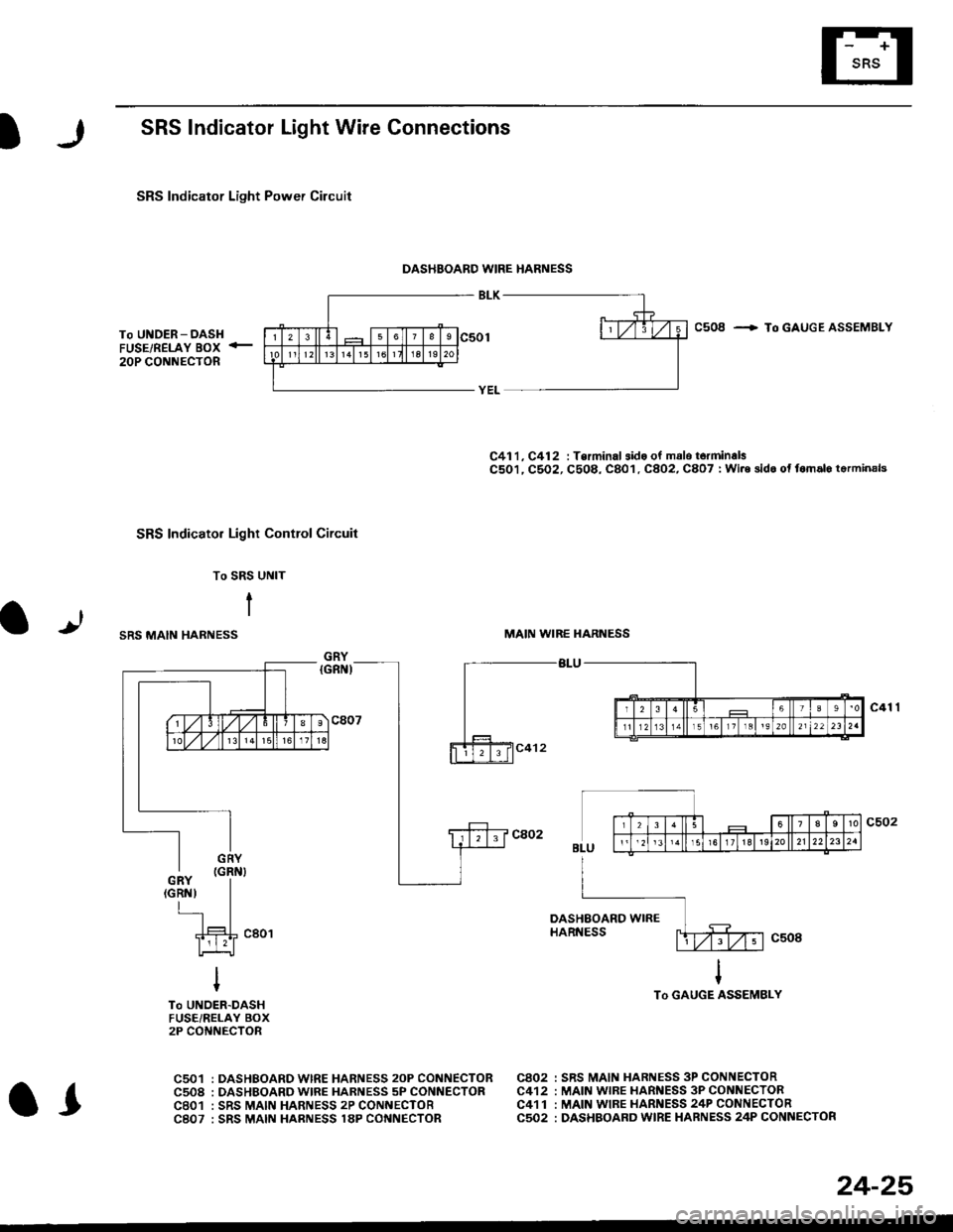
SRS Indicator Light Wire Connections
SRS Indicator Light Power Circuit
DASHBOARD WIRE HARNESS
To UNDER-DASHFUSE/RELAY BOX -
20P CONNECTOR
SRS Indicato. Light Control Circuit
To SRS UNIT
tI
SRS MAIN HARNESS
C41 1, C412 : Terminal sido of mdlo t6rminalsC501, C5O2, C508, C801. C802, C807 : Wi.6 sidc of fomalo t.rminals
MAIN WIBE HARNESS
BLU
C508 -+ To GAUGE ASSEMBLY
c41 1
To GAUGE ASSEMBLY
at
C501 : DASHBOARDWIRE HARNESS 2oP CONNECTORC508 : DASHBOARD wlRE HARNESS 5P CONNECTORC801 : SRS MAIN HARNESS 2P CONNECTORC807 : SRS MAIN HARNESS 18P CONNECTOR
C802 : SRS MAIN HARNESS 3P CONNECTORC412 : MAIN WIRE HARNESS 3P CONNECTORC41 1 : MAIN WIRE HARNESS 24P CONNECTORC502 : DASHBOARD WIRE HARNESS 24P CONNECTOR
GRY
OI
24-25