1998 HONDA CIVIC Atf
[x] Cancel search: AtfPage 876 of 2189

Description
Clutches/Reverse Brake/Planetary Gear/Pulleys
Clulches/Reverse Brake
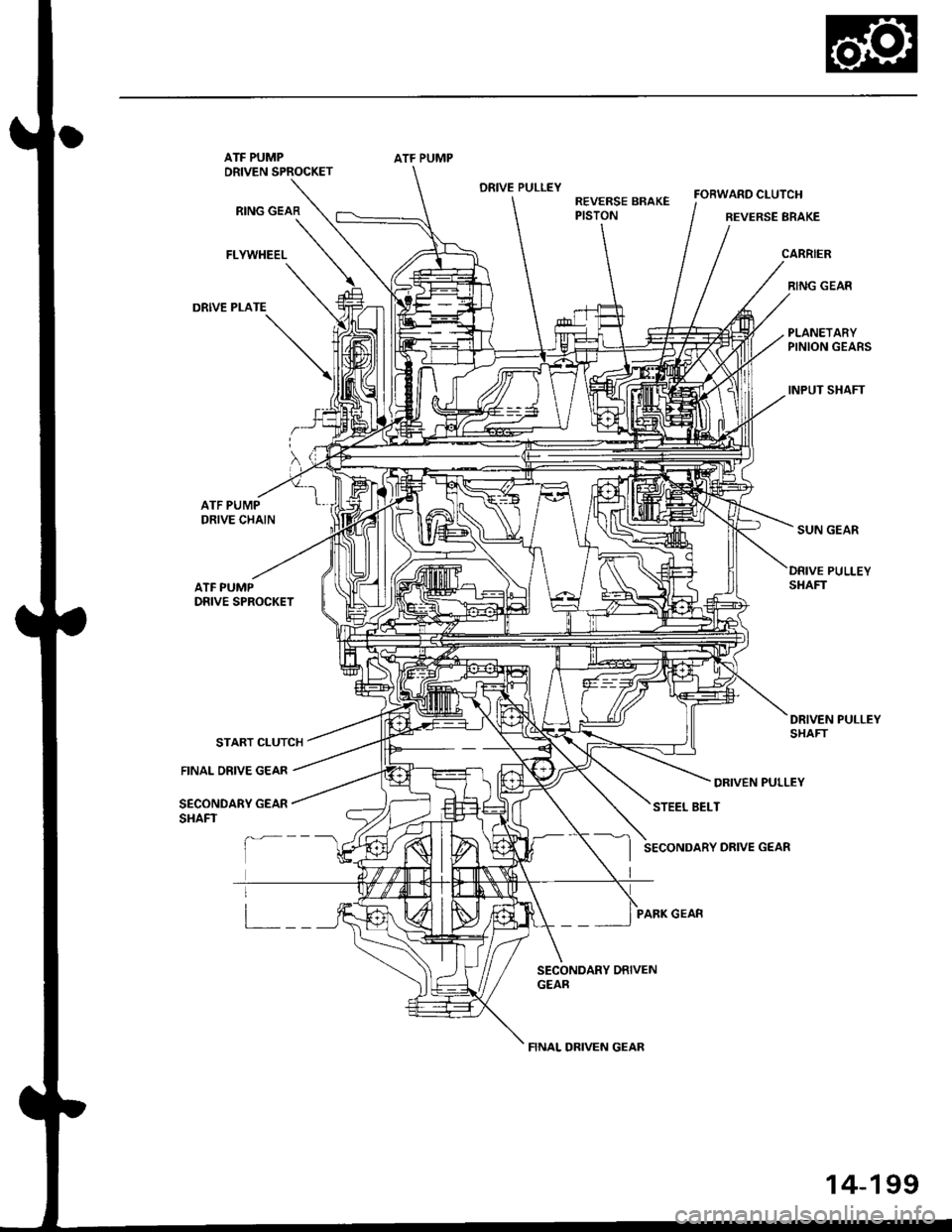
The CVT uses the hydraulically-actuated clutches and brake to engage or disengage the transmission gears. When
hydraulic pressure is introduced into the clutch drum and the reverse brake piston cavity, the clutch piston and the reverse
brake piston move. This presses the friction djscs and the steel plates together, locking them so they don't slip. Power is
then transmitted through the engaged clutch pack to its hub-mounted gear. and through engaged ring gear to pinion
gears.
Likewise, when the hydraulic pressure is bled from the clutch pack and the reverse brake piston cavity, the piston releases
the friction discs and the steel plates, and they are free to slide past each. This allows the gear to spin independently on its
shaft, transmitting no power.
Start Clutch
The start clutch, which is located at the end of the driven pulley shaft, engages/disengages the secondary drive gear.
The start clutch is supplied hydraulic pressure by its ATF feed pipes within the driven pulley shaft.
Forward Clutch
The forward clutch, which is located at the end of the drive pulley shaft, engages/disengages the sun gear.
The forward clutch is supplied hydraulic pressure by its ATF feed pipe within the drive pulley shaft.
Reverse Brake
The reverse brake, which is located inside the inte.mediate housing around the ring gear, locks the ring gear in E posi-
tion. The reverse brake discs are mounted to the ring gear and the reverse brake plates are mounted to the intermediate
housing. The reverse brake is supplied hydraulic pressure by a circuit connected to the internal hydraulic circuit.
Planetary Gear
The planetary gear consists of a sun gear, a carrier assembly, and a ring gear. The sun gear is connected to the input shaft
with splines. The pinion gears are mounted to the carrier which is mounted to the fo.ward clutch drum. The sun gear
inputs the engine power via the input shaft to the planetary gear, and the carrier outputs the engine power. The ring gear
is only used for switching the rotation direction of the pullev shafts,
In E. E, and E positions (forward range), the pinion gears don't rotate and revolve with the sun gear, so the carrier
rotates. In E] positjon {reverse range), the reverse brake locks the ring gear and the sun gear drives the pinion gears to
rotate. The pinion gears rotate and revolve in the opposite direction from the rotation direction of the sun gear, and the
carrier rotates with pinion gear revolution.
Pulleys
Each pulley consists of a movable face and a fixed face, and the effective pulley .atio changes with engine speed. The
drive pulley and the driven pulley are linked by the steel belt.
To achieve a low pulley ratio, high hydraulic pressure works on the movable face of the driven pulley and reduces the
effective diameter of the drive pulley. and a lower hydraulic pressure works on the movable face of the drive pulley to
eliminate the steel belt slippage. To achieve a high pulley ratio, high hydraulic pressure works on the movable face of the
drive pulley and reduces the eifective diameter of the driven pulley, and a lower hydraulic pressure works on the movable
face of the driven pulley to eliminate the steel belt slippage.
b
14-198
Page 877 of 2189
ATF PUMPDRIVEN SPROCKET
RING GEAR
FLYWHEEL
DRIVE PLATE
ATF PUMP
DRIVE PULLEYREVERSE BRAKEPISTON
FORWARD CLUTCH
BEVERSE BRAKE
CARRIER
RING GEAR
PLANETARYPINION GEARS
INPUT SHAFT
ATF PUMPDRIVE CHAIN
ATF PUMPDRIVE SPROCKET
START CLUTCH
DRIVEN PULLEY
STEEL BELT
SECONDARY DRIVE GEAR
PARK GEAR
DRIVEN PULLEYSHAFT
FINAL DRIVE GEAR
SECONDARY GEARSHAFT
a--
i___
il
14-199
Page 886 of 2189
Description
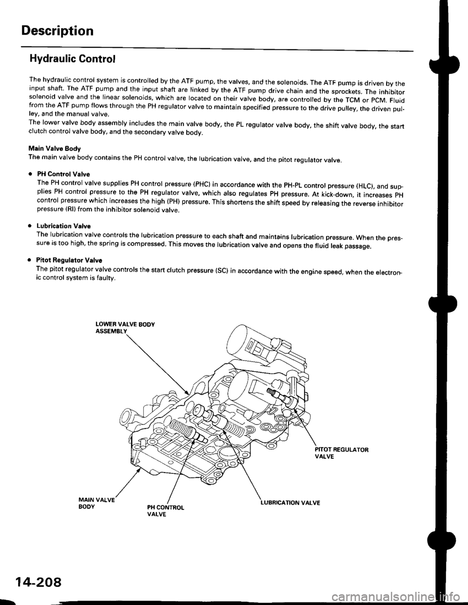
Hydraulic Control
The hydraulic control system is controlled by the ATF pump. the valves, and the solenoids. The ATF pump is driven by theinput shaft. The ATF pump and the input shaft are linked by the ATF pump drive chain and the sprockets, The inhibitorsolenoid valve and the linear solenoids. which are located on their valve body, are controlled by the TCM or pcM. Fluidfrom the ATF pump flows through the PH regulator valve to maintain specified pressure to the drive pulley, the driven pul-ley, and the manual valve,
The lower valve body assembly includes the main valve body, the PL regulator valve body, the shift valve body, the startclutch control valve body, and the secondary valve bodv.
Main Valve Eody
The main valve body contains the pH control valve, the rubrication valve, and the pitot regulator valve.
PH Control Valve
The PH control valve supplies PH control pressure (PHCI in accordance with the pH-pL control pressure (HLc), and sup-plies PH control pressure to the PH regulator valve, which also regulatss PH pressure. At kick-down, it increases pHcontrol pressure which increases the high (PH) pressure. This shortens the shift speed by releasing the reverse inhibitorpressure (Rl)from the inhibitor solenoid valve.
Lubrication Valve
The lubrication valve controls the lubrication pressure to each shaft and maintains lubrication pressure. When rne pres-sure is too high, the spring is compressed. This moves the lubrication valve and opens the fluid leak passage.
Pitot Regulalor Valv6
The pitot regulator valve controls the start clutch pressure (SC) in accordance with the engine speed, when the electron-ic control system is faulw.
MAIN VAIVEBODY
L.
14-208
Page 887 of 2189

Secondary Valve Body
The secondary valve body contains the PH regulator valve. the clutch reducing valve' the start clutch valve accumulator'
and the shift inhibitor valve
PH Regulator Valve
The pi regulator valve maintains hydraulic pressure supplied from the ATF pump. and supplies PH pressure to the
hvdraulic control circuit and the lubrication circuit. PH pressure is regulated at the PH regulator valve by the PH control
pressure (PHC) from the PH control valve.
Cluteh Reducing Valvo
The clutch reducing valve receives PH pressure from the PH regulator valve and regulates the clutch reducing pressure
(cR). The clutch reducing valve supplies clutch pressure (cR) to the manual valve and the start clutch control valve' and
supplies signal pressure to the PH-PL pressure control valve. the shift control valve, and the inhibitor solenoid valve'
Start Clutch Valv€ Accumulator
The start clutch vatve accumutator stabilizes the hydraulic pressure that is supplied to the start clutch'
Shift Inhibitor Valve
The shift inhibitor valve switches the fluid passage to switch the start clutch control from electronic control to hydraulic
control when the electronic control system is faulty. lt also suppliss clutch reducing pressure (cR) to the pitot regulator
valve and the pitot lubrication pipe.
START CLUTCH VALVE
SECONDARY VALVEBODY
SHIFT INHIBITOE VALVE
(cont'd)
PH REGULATOR VAL
REDUCING VALVE
14-209
Page 890 of 2189
Description
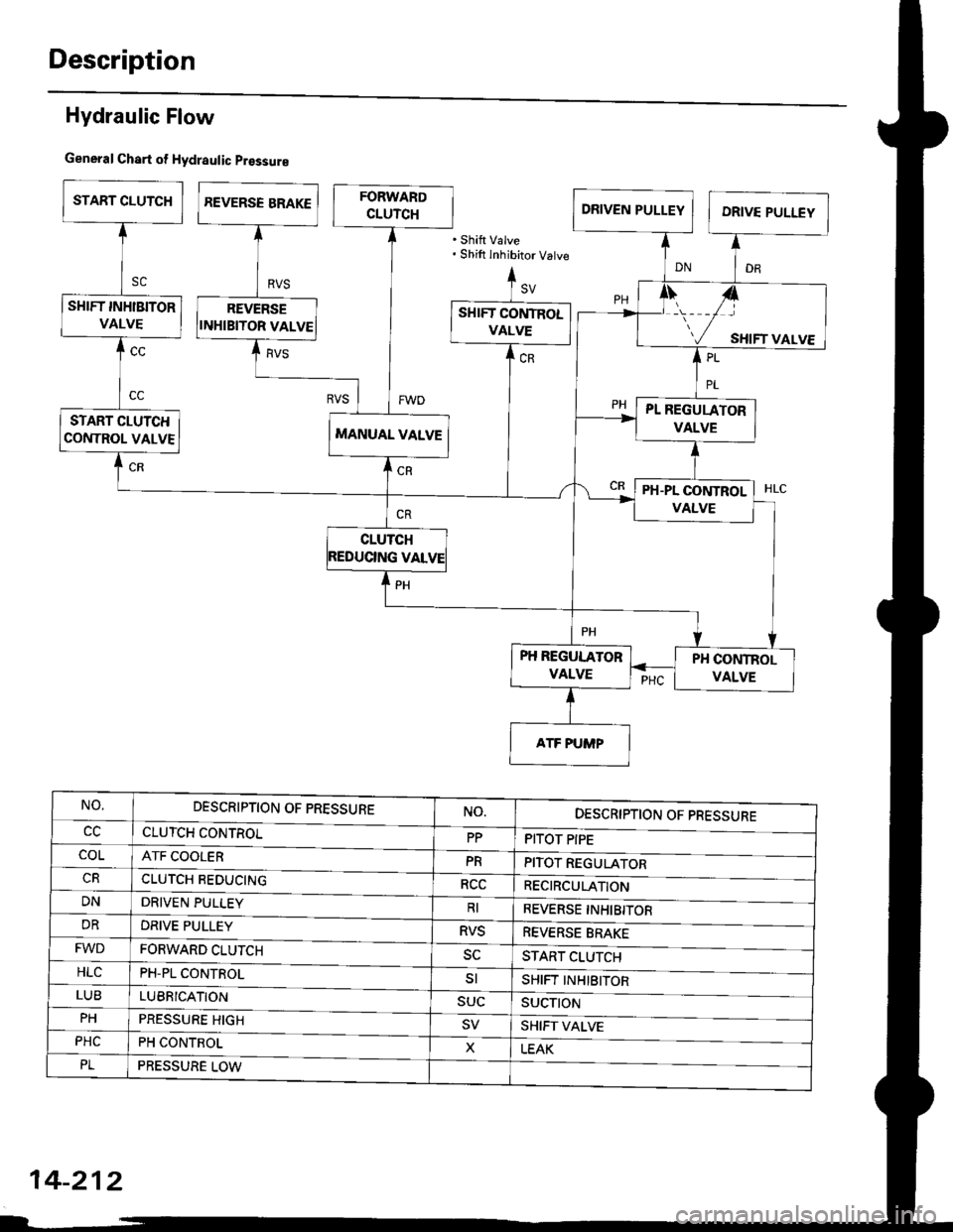
Hydraulic Flow
General Chart of Hydraulic prossure
'Shift Valve. Shift inhibitor Vatve
PH REGULATOR
VALVE
NO.DESCRIPTION OF PRESSURE
CLUTCH CONTROL
ATF COOLER
CLUTCH REDUCING
NO.DESCRIPTION OF PRESSURE
PITOT PIPEccPP
coLPRPITOT REGULATOR
RECIRCULATIONRCC
DNDRIVEN PULLEYRIREVERSE INHIBITOR
REVERSE BRAKE
START CLUTCH
SHIFT II"IHlBITOR
SUCTII'N
SHIFT VALVE
LEAK
DRDRIVE PULLEYRVS
FWDFORWARD CLUTCH
PH-PL CONTROL
sc
HLCsl
LUBLUBBICATION
PRESSURE HIGH
SUC
PH
PHCPH CONTROLX
PLPRESSURE LOW
14-212
Page 891 of 2189

E Position
Astheengineturns.theATFpumpa|sostartstooperate.F|uidfromtheATFpumpf|owstothePHregu|atorva|veandthe
c|Utchreducingva|ve.ThePHregu|atorva|veregu|ateshighpressure(PH).andsendittotheshiftVa|veandthePLregU'
latorvalve.Thehighpressure(PH)flowstothemovablefaceofthedrivenpulleyviatheshiftvalve'andturnsintolow
pressure(PL)atthePLregu|atorva|ve.Thelowpressure(PL}f|owstothemovab|e'aceofthedrivepu||eYviatheshift
valve. At this time, the pulley ratio remarns low'
Thehighpressure(px)uecomesttrectutchreducingpressure(CR)atthec|utchreducingva|Ve.Thec|utchreducingpres.
sure (CR) flows to the start clutch cont'oi uatt". tn"lt"n'al valve' the PH-PL control valve' and the shift control valve' and
is intercepted bY those valves
Under this condition, hydraulac pressure is not applied to the clutches and reverse brake'
(cont'd)
14-213
Page 968 of 2189
Linear Solenoids/lnhibitor Solenoid
)Test
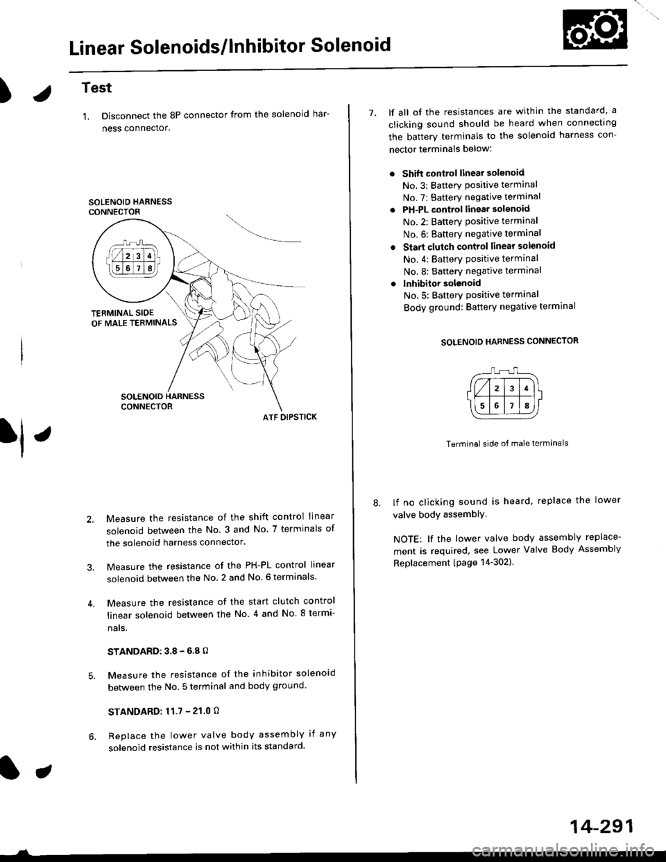
1. Disconnect the 8P connector from the solenoid har-
ness connector.
SOLENOID HARNESSCONNECTOR
ATF OIPSTICK
Measure the resistance of the shift control linear
solenoid between the No. 3 and No. 7 terminals of
the solenoid harness connector.
Measure the resistance of the PH-PL control linear
solenoid between the No. 2 and No. 6 terminals
Measure the resistance of the start clutch control
linear solenoid between the No 4 and No. 8 termi-
nats,
STANDARD:38-6.8O
Measure the resistance of the inhibitor solenoid
between the No. 5 terminal and body ground
STANDARD:11.7 - 21.0 O
Replace the lower valve body assembly if any
solenoid resistance is not within its standard.
7. lf all ot the resistances are within the standard, a
clicking sound should be heard when connectrng
the batterv terminals to the solenoid harness con-
nector terminals below:
Shift control linear solsnoid
No.3: Batterv Positive terminal
No. 7: Battery negative terminal
PH-PL control linear solenoid
No.2: Batterv oositive terminal
No. 6: Baftery negative terminal
Start clutch control linear solenoid
No. 4: Battery Positive terminal
No.8: Battery negative terminal
lnhibitor solsnoid
No,5: Batterv Positive terminal
Body ground: Battery negative termrnal
SOLENOID HARNESS CONNECTOR
Terminal side of male terminals
lf no clicking sound is heard, replace the lower
valve body assemblY,
NOTE: lf the lower valve body assembly replace-
ment is required, see Lower Valve Body Assembly
Replacement (page 14-302).
14-291
Page 972 of 2189
t.
rl,
fl,
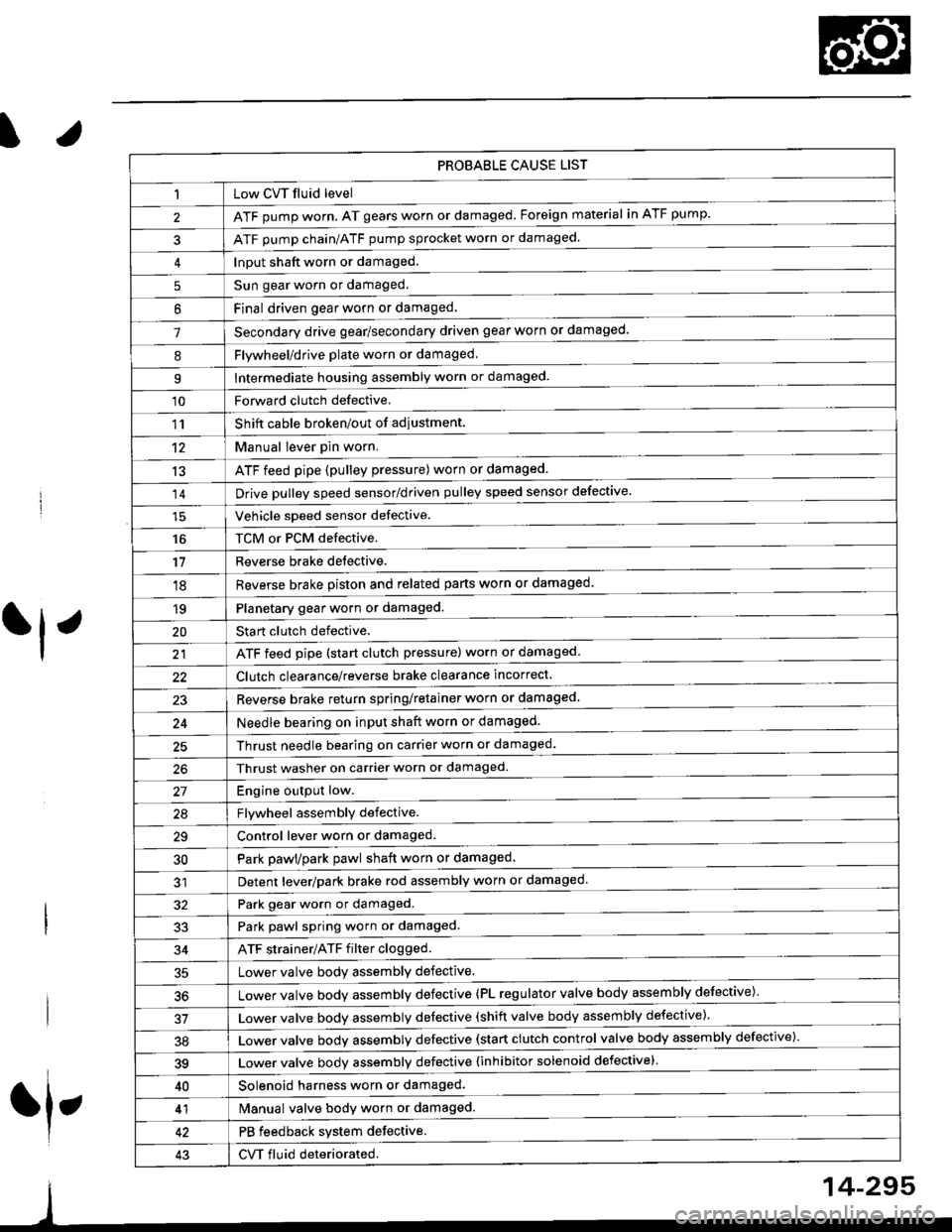
PROBABLE CAUSE LIST
Low CVT fluid level
ATF pump worn. AT gears worn or damaged. Foreign material in ATF pump.
ATF pump chain/ATF pump sprocket worn or damaged.
Input shaft worn or damaged.
Sun gear worn or damaged.
Final driven oear worn or damaqed,
Secondary drive gear/secondary driven gear worn or damaged-
5
6
1
8Flywheel/drive plate worn or damaged.
Intermediate housing assembly worn or damaged.9
'10Forward clutch defective.
Shift cable broken/out of adiustment.
M"nu"t t"uffi
ATF feed pipe (pulley pressure) worn or damaged.
Vchiclc speed sensor defective.
TCM or PCM defective.
Reverse brake detective.
1'�r
't2
13
14
16
'11
'18
1qPlanetary gear worn or damaged.
Sta rt clutch defective.
ATF feed pipe (start clutch pressure) worn or damaged
20
t't
Clutch clearance/reverse brake clearance incorrect.
23Reverse brake return spring/retainer worn or damaged
24Needle bearing on input shaft worn or damaged.
25Thrust needle bearing on carrier worn or damaged.
Thrust washer on carrier worn or damaged.
Enoine outout low.------------------------
Flvwhcel assemblv defective.
Control lever worn or damaged.
Park pawl/park pawl shaft worn or damaged
Detent lever/park brake rod assembly worn or damaged
27
29
30
32Park gear worn or damaged.
Park pawl spring worn or damaged.
ATF strainer/ATF filter clogged.
Lower valve body assembly defective.
Lower valve bodv assemblv defective (PL regulator valve body assembly defective)'
33
34
50
Lower valve bodv assembly defective (shift valve body assembly defective).
Lower valve bodv assemblv defective (start clutch control valve body assembly defective)'
39Lower valve bodv assemblv defective {inhibitor solenoid defective}
40Solenoid harness worn or damaged.
Manual valve body worn or damaged.
PB feedback system defective.
CVT fluid deteriorated.
41
43
14-295