Page 1164 of 2189
Front Brake Pads
2056 Type:
@. Never use an air hose or dry brush to clgan brake
assemblies.
. Use an OsHA-approved vacuum cleanor lo avoid
breathing broke dust.
Inspection and Replacement (cont'dl
1. Loosen the front wheel nuts slightly. then raise the
vehicle, and support it on safety stands. Remove
the front wheels.
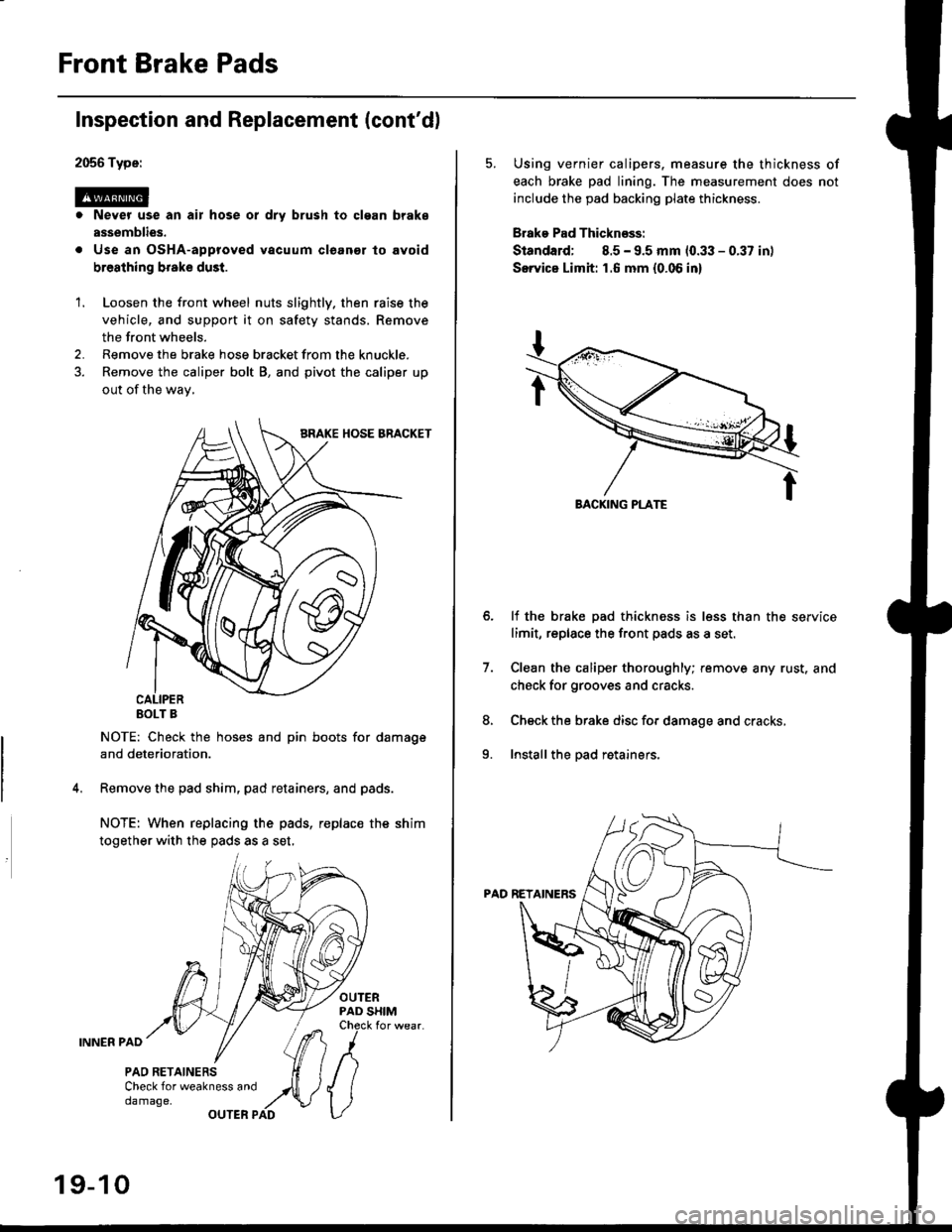
2. Remove the brake hose bracket from the knuckle.
3. Remove the caliper bolt B, and pivot the caliper up
out of the wav,
EOLT B
NOTE: Check the hoses and pin boots for damage
and deterioration.
Remove the pad shim, pad retainers, and pads.
NOTE: When replacing the pads, replac€ the shim
together with the pads as a set,
OUTERPAD SHIMCheck for wear.
INNER PAD
PAO RETAINERSCheck for weakness anddamage,OUTER PAD
19-10
5. Using vernier calipers. measure the thickness of
each brake pad lining. The measurement does not
include the pad backing plate thickness.
Brake Pad Thicknsss:
Standard; 8.5 - 9.5 mm 10.33 - 0.37 in)
Servica Limh: 1.6 mm {0.06 in}
lf the brake pad thickness is less than the service
limit, replace the front pads as a set,
Clean the caliper thoroughly; remove any rust. and
check for grooves and cracks.
Check the brake disc for damage and cracks,
Install the pad retainers.
7.
8.
9.
Page 1166 of 2189
Front Brake Disc
Disc Runout Inspection
L
2.
Loosen the front wheel nuts slightly, then raise the
vehicle, and support it on safety stands. Remove
the front wheels.
Remove the brake pads (see page 19,8).
Inspect the disc surface for damage and cracks.
Clean the disc thoroughly and remove all rust.
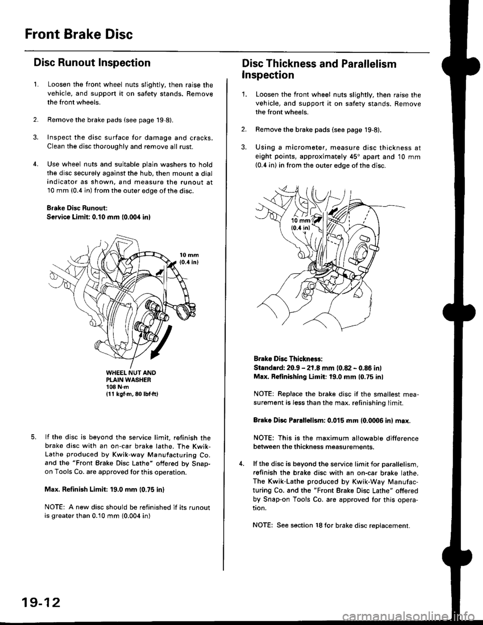
Use wheel nuts and suitable plain washers to hold
the disc securely against the hub, then mount a dial
indicator as shown, and measure the runout at
10 mm (0.4 in) from the outer edge of the disc.
Brake Disc Runout:
Service Limit: 0.10 mm (0.004 inl
WHEEL NUT ANOPLAIN WASHER'108 N.m(11 kg{.m, 80 lbf.ft)
lf the disc is beyond the service limit, refinish thebrake disc with an on-car brake lathe, The Kwik-Lathe produced by Kwik-way Manufacturing Co.and the "Front Brake Disc Lathe" offered by Snap-on Tools Co. are approved for this operation.
Max. Refinish Limit: 19.0 mm (0.75 in)
NOTE: A new disc should be refinished if its runout
is greater than 0.10 mm (0.004 in)
19-12
Disc Thickness and Parallelism
Inspection
1.Loosen the front wheel nuts slightly, then raise the
vehicle, and support it on safety stands. Remove
the front wheels.
Remove the brake pads (see page 19-8).
Using a micrometer, measure disc thickness at
eight points, approximately 45" apart and 10 mm(0.4 in) in from the outer edge of the disc.
Brake Dbc Thickn6s:
Standlrd: 20.9 - 21.8 mm (0.82 - 0.86 in)
Max. Refinishing Limit: 19.0 mm 10.75 inl
NOTE: Replace the brake disc if the smallest mea-
surement is less than the max. refinishinq limit.
Brake Disc Parallelism: 0.015 mm (0.fit06 in) max.
NOTE: This is the maximum allowable difference
between the thickness measurements.
lf the disc is beyond the service limit for parallelism,
refinish the brake disc with an on-car brake lathe.
The Kwik-Lathe produced by Kwik-Way Manufac-
turing Co. and the "Front Brake Disc Lathe" offered
by Snap-on Tools Co. are approved for this opera-
tion.
NOTE: See section 18 for brake disc reDlacement.
Page 1178 of 2189
Rear Brake Pads
Inspection and Replacement
Never use an air hose or dry brush to clean brakeassemblies.
Use an OsHA-apptoved vacuum cl€aner to avoidbreathing brake dust,
Block the front wheels, loosen the rear wneet nutsslightly, support the rear of the vehicle on safetystands, then remove the rear wheels.
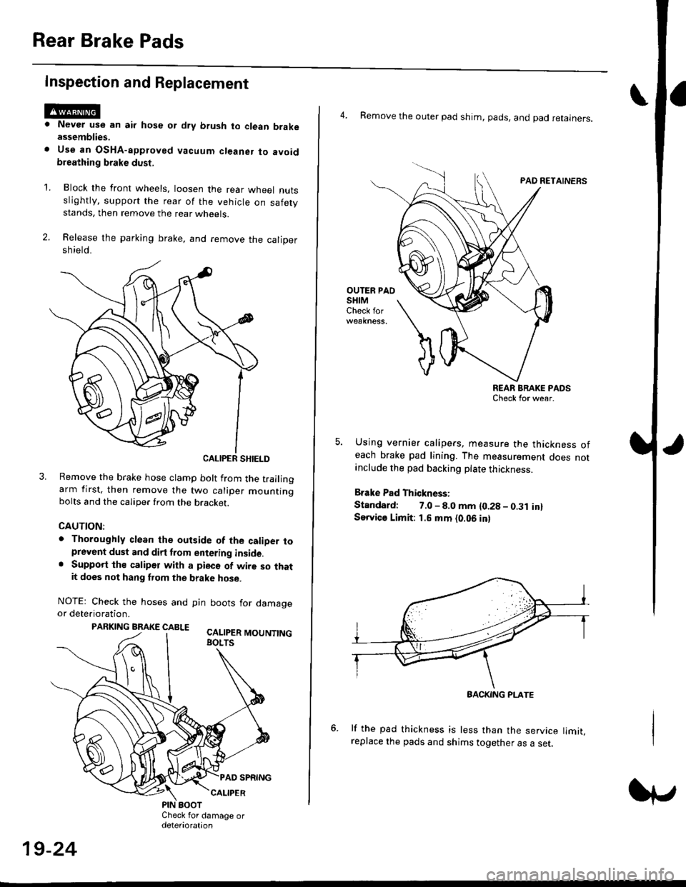
Release the parking brake, and remove the calioersh ield.
CALIPER SHIELD
Remove the brake hose clamp bolt from the trailingarm first, then remove the two caliper mountingbolts and the caliper from the bracket.
CAUTION:
. Thoroughly clean the outside of the caliDer toprevent dust and dirt trom entering inside.. Support the calipor with a pieco of wire so thatit does not hang fuom the brake hose.
NOTEr Check the hoses and pin boots for damageor deterioration.
PARKING BRAKE CABLE ^.. ._-_ ---.
'L
19-24
4. Remove the outer pad shim, pads, and pad retainers.
PAO RETAINERS
OUTER PAOSHIMCheck for
REAR BRAKE PADSCheck for wear.
Using vernier calipers, measure the thickness ofeach brake pad lining. The measurement does notanclude the pad backing plate thickness.
Brake Pad Thickness:
Standard: 7.0 - 8.0 mm {0.28 - 0.31 in}Service Limit: 1.5 mm {0.06 in}
lf the pad thickness is less than the service limit,replace the pads and shims together as a set.
BACKING PI-ATE
Page 1180 of 2189
Rear Brake Disc
Disc Runout Inspection
1.Loosen the front wheel nuts slightly, then raise thevehicle, and suppon it on safety stands. Removethe front wheels.
Remove the brake pads (see page 19-24).
Inspect the disc surface for damage and cracks.Clean the disc thoaoughly, and remove a
rust.
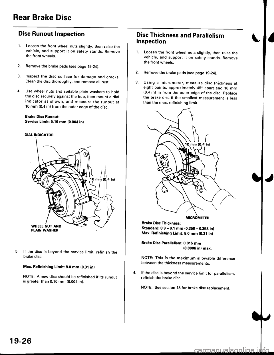
Use wheel nuts and suitable plain washers to holdthe disc securely against the hub. then mount a dialindicator as shown. and measure the runout at10 mm (0.4 in) from the outer edge of the disc.
Brake Disc Runout:
Service Limit:0.10 mm {0.00,t in)
5. lf the disc is beyond the service limit, refinish thebrake disc,
Max. Retinishing Limit: 8.0 mm {0.31 in)
NOTE: A new disc should be refinished if its runoutis greater than 0.10 mm (0.004 in).
19-26
Disc Thickness and Parallelism
Inspection
1. Loosen the front wheel nuts slightly, then raise thevehicle, and support it on safety stands. Removethe front wh6els.
2. Remove the brake pads (see page j9-24).
3. Using a micrometer. measure disc thickness aterght points, approximately 45" apart and 1o mm{0.4 in) in from the outer edge of the disc. Replacethe brake disc if the smallest measurement is lessthan the max. refinishing limit.
Brake Disc Thickness:
Standard: 8.9 - 9.1 mm (0.350 - 0.358 in)Max. Rsfinishing Limit: 8.0 mm {0.31 in}
Brake Disc Parallelirm: 0.015 mm(0.0006 inl msx.
NOTE; This is the maximum allowable differencebetween the thickness measurements.
4. lf the disc is beyond the service limit for Darallelism.refinish the brake disc.
NOTE; See section 18 for brake disc replacement.
Page 1189 of 2189
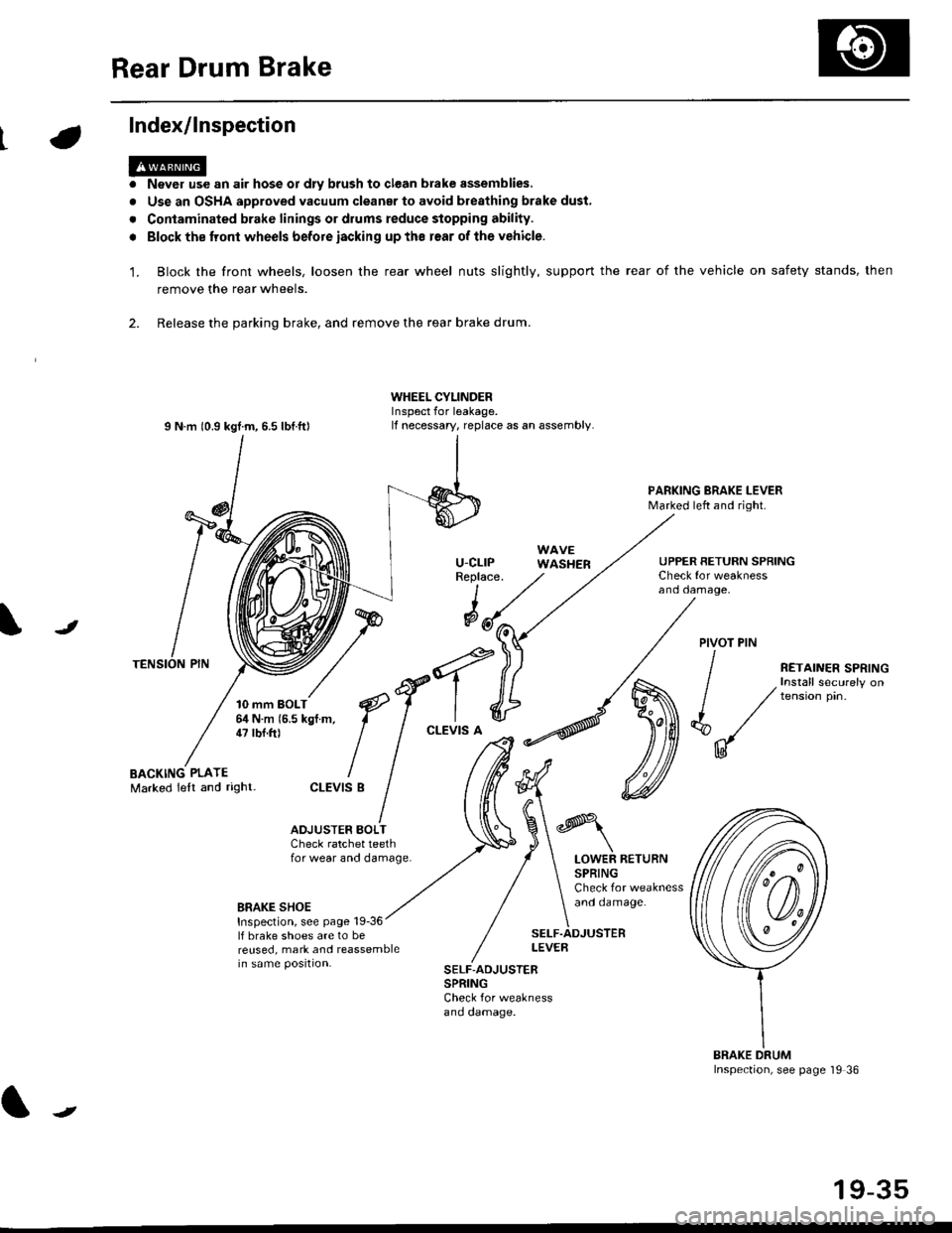
Rear Drum Brake
Index/lnspection
'1.
a
a
Never use an air hose or dly brush to clean brake assemblies,
Use an OSHA approved vacuum cleanar to avoid breathing brake dust,
Contaminated brake linings or drums reduce stopping ability.
Block the tront wheels before iacking up ths r€ar of lhe vehicle.
Block the front wheels, loosen the rear wheel nuts slightly, support the rear of the vehicle on safety stands, then
remove the rear wheels.
2. Release the parking brake, and remove the rear brake drum.
I N m 10.9 kgtm, 6.5 lbf.ftl
TENSION PIN
10 mm BOLT6,1N m 15.5 kgf m,47 tbf.ft)
WHEEL CYLINDERInspect for leakage.lf necessary, replace as an assembly.
u-cLrPReplace.
WAVEWASHER
PARKING BRAKE LEVERMarked left and right.
Check for weaknessano oamage,
UPPER RETURN SPRING
I
@JPIVOT PIN
BACKING PLATEMarked lelt and right-
/
€f-l.^
I I
*'t")
ctEv'sB
/ (t
/ ,.ro,".r r.*,"n
/ , Install securely on
| / tension pin.
d"/
IU
ADJUSTER BOI-TCheck ratchet teethfor wear and damage.LOWER RETURNSPRINGCheck for weaknessand oamage.BRAKE SHOEInspection, see page 19-36lf brake shoes are to bereused, mark and reassemblein same position.
SELF.ADJUSTERLEVEB
SELF-ADJUSTERSPRINGCheck for weaknessano oamage.
BRAKE DRUMInspection, see page '19 36
t
19-35
Page 1198 of 2189
Component Locations
ta
SERVICE CHECK CONNECTOR {2PIBIGHT.REAR WHEELSENSOR CONNECTORMOOULATOR UNITABS CONTROL UNIT
RIGHT-REAR WHEEL SENSOR
LEFT.R€AR WHEELSENSOR CONNECTOR
J
UNDER.DASH FUSE/RELAY 8OX
LEFT.FRONT WHEEL SENSOR
ABS +B (20 A) FUSE
UNDER.HOOD FUSE/RELAY BOX
lcl lilo Al FUSE
ABS INDICATOR LIGHT
UNOEF.DASI{ FUSE/RELAY BOX
HORN/STOP I15 A) FUSE
UNDER.HOOO ABS FUSE/RELAY BOX
PUMP MOTOR {'O A} FUSE
PUMP MOTOR BELAY
E
o
METEB I7.5 AI FUSE
0
0
0
00000 n
00000 u
BR DEF RLY 17,5 A) FUSE
t
MTR CHECK (7.5 AI FUSE
19-45
Page 1199 of 2189
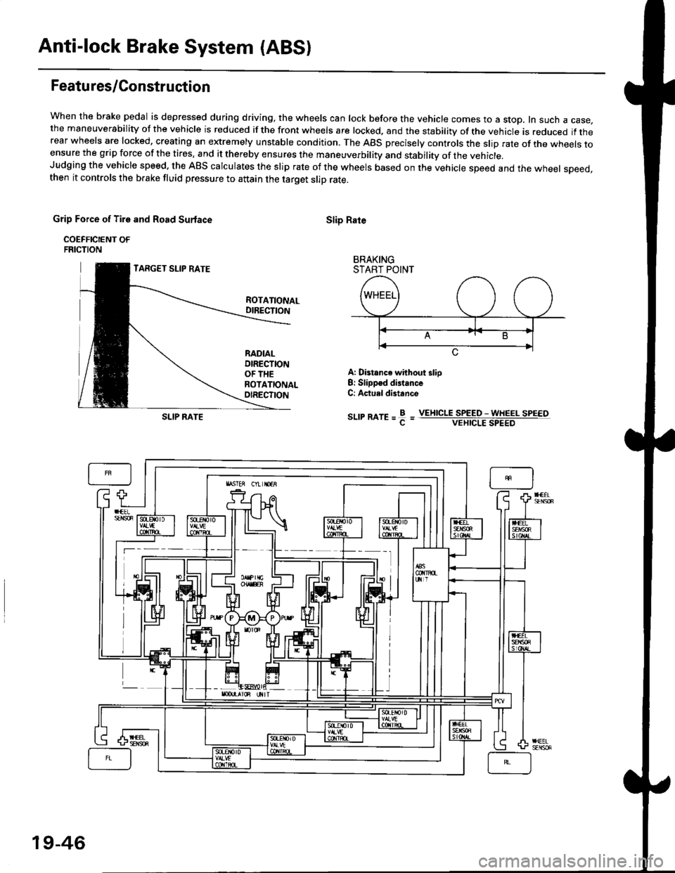
Anti-lock Brake System (ABSI
Featu res/Construction
When the brake pedal is depressed during driving, the wheels can lock before the vehicle comes to a stop, In such a case,the maneuverability of the vehicle is reduced if the front wheels are locked, and the stability of the vehicle is reduced if therear wheels are locked, creating an extremely unstable condition. The ABS precisely controls the slip rate of the wheels toensure the grip force of the tires. and it thereby ensures the maneuverbility and stability of the vehicle.Judging the vehicle speed. the ABS calculates the slip rate of the wheels based on the vehicle speed and the wheel speed,then it controls the brake fluid pressure to attain the target slip rate.
Grip Force of Tire and Road Surlace
COEFFICIENT OFFRICTION
TARGET SLIP RATE
Slip Rate
BRAKINGSTART POINT
ROTATIONALDIRECTION
RADIALDIRECTIONOF THEROTATIONALOIRECTION
A: Distance without slio8: Slippsd distanceC: Actuel distance
sr-rrmre=f=SLIP RATEVEIIICLE SPEED - WHEEL SPEEOVEHICLE SPEED
19-46
Page 1205 of 2189
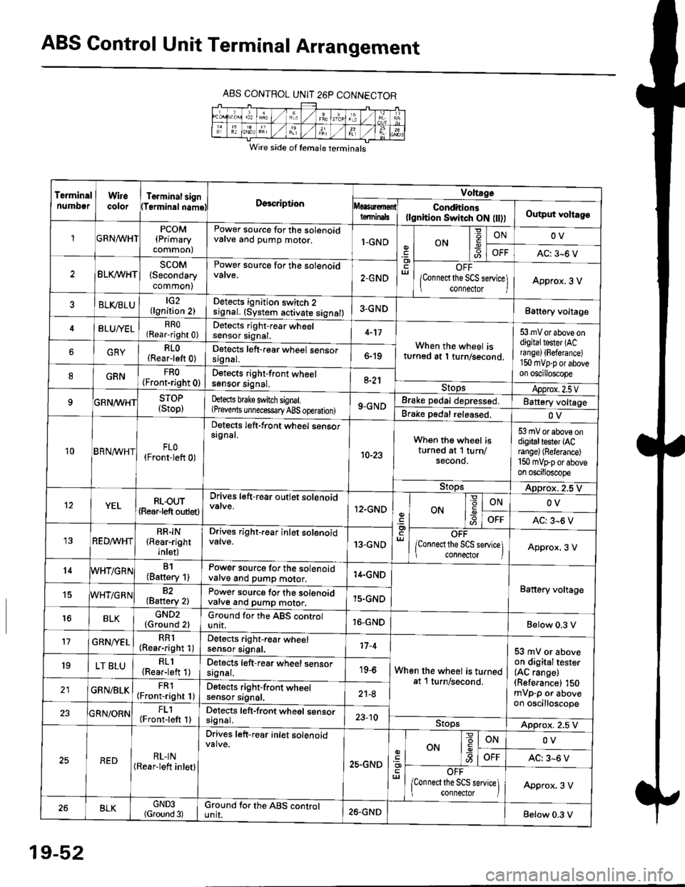
ABS Control Unit Terminal Arrangement
ABS CONTROL UNIT 26P CONNECTOR
Wire side of temale terminals
Terminalnumo0rWirecolorTerminal signTerminalnamoDgscriptionVoltage
Conditions(lgnition Switch ON flt))Output voltagoteminals
PCOM(Primary
common)
Power source for the solenoidvalve and pump motor.1-GNDON
=ONOV
AC: 3-6 V
BLK/WHTscoM(Secondary
common)
Power source for the solenoid
2.GNDOFF
lConnect the SCS service\
conneclor lApprox. 3 V
ELVBLUtG2(lgnition 2)Detects ignition switch 2
!9nal. (system activate signal)3-GNDBatt€ry voltage
BLU/YELRRO(Rear-right 0)Detects right-rear wheelsensor signal.4-17
When the wheel isturned at 1 turn/second.
53 mV or above ondigitaltester (ACra nge) {Fefera nce)150 mvp-p or aboveon oscilloscope
6GRYRLO(Rear-left 0)Detects left-rear wheel sensorsrgnal.6-19
8GRNFRO(Front-right 0)D€tects right-front wheelsgnsor srgnal,a-21StopsApprox.2.5VSTOP(Stop)hects brake switch signal.(Prevents unnecess€ry ABS operation)9-GNDBrake pedal depressed.Battery voltage
Brake pedal released.OV
10BRN^/vHTFLO(Front-left 0)
Detects left-front wheel sensorsignal.
10-23
When the wheel isturned at 1 turn/secono.
53 mV or above ondigitaltester (ACrange) (Referance)
150 mVFporaboveon oscilloscope
9!opsApprox. 2.5 V
12YELRLOUT(Rearjeft outlet)
Drives left-rear outlet solenoid
12.GNDON-9ONOV
OFFAC: 3^6 V
REDMHTRR]N(Rear-right
inlet)
Drives right-rear inlet solenoidvalve.13-GNDOFF
lconnect the SCS service]i connector IApprox. 3 V
14B1(Battery 1)Power source for the solenoidvatve and pump motor.14.GND
Battery voltage15WHT/G R N82(Baftery 2)Power source for the solenoidvarve ano pump motor.15.GND
r6BLKGND2{Ground 2)Ground for the ABS controlunit.16-GNDBelow 0.3 V
17GRN/'/ELRR1(Rear-right 1)Detects right-rear wheelsensor signal.17-4
When the wheel is turnedat 1 turn/second.
53 mV or aboveon digitaltester(AC range)(Referance) 150mVp-p or aboveon oscilloscope
19LT BLURLl(Rea.-left 1)Detects left-rear wheel sensorsagnal.19-6
GRN/BLKFRl(Front-right 1)Detects right-front wheelsensor signal.21-8
FL1(Front-left 1)Detects left-front wheel sensorsignal.23-10StopsApprox. 2.5 V
REDRL-IN(Rear-lett inletl
Drives left-r€ar inlet solenoid
25.GND
ut
ON
'6
-9ONOV
OFFAC: 3-6 V
OFF
lconnect the SCS service] connector lApprox. 3 V
BLKGND3(Ground 3)Ground for the ABS cgntrolunit.26.GNDBelow 0.3 V
19-52