Page 233 of 2189

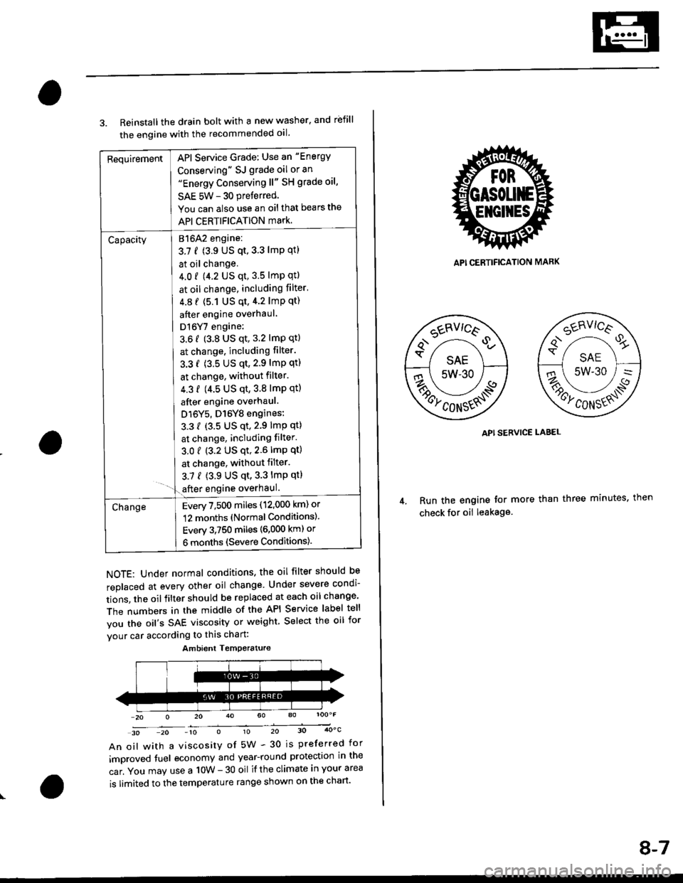
RequirementAPI Service Grade: Use an "Energy
Conserving" SJ grade oil or an"Energy Conserving ll" SH grade oil,
SAE 5W - 30 preferred
You can also use an oil that bears the
API CERTIFICATION mark.
Capacity[atolz engine:
3.7 f (3.9 US qt,3.3 lmp qtl
I at oil change.
J 4.0 r 9.2 US qt, 3.5 lmp qtl
I at oil change, including filter'
| 4.8 f (5.1 Us qt,4.2 lmp qt)
I after engine overhaul
I Dl6Y7 engine:
3.6 f (3.8 US qt, 3.2 lmP qt)
I at change. including filter.
I 3.3 f (3.5 US qt,2.9 lmP qtl
I at change, without filter.
I 4.3 f (4.5 us qt,3.8 lmp qtl
I after engine overhaul.
J D16Y5, D16Y8 engines:
L 3.3 { {3.5 US qt,2.9 lmp qt}
I at change, including filter.
3.01 (3.2 US qt,2.6lmp qt)
I at change, withoutfilter.
3.7 { (3.9 US qt,3.3 lmp qt}- '1.€fter engine overhaul.
ChangeEvery 7,500 miles (12,000 km) or
12 months (Normal Conditions).
Every 3,750 miles (6,000 kml or
6 months (Severe Conditions).
3. Reinstall the drain bolt with a new washer. and rbfill
the engine with the recommended oil.
NOTE: Under normal conditions, the oil filter should be
replaced at every other oil change Under severe condi-
tions, the oilfilter should be replaced at each oil change'
The numbers in the middle of the API Service label tell
you the oil's SAE viscosity or weight Select the oil for
vour car according to this chart:
30 20 -10 010 20 30 4OoC
An oil with a viscosity of 5W - 30 is preferred for
improved tuel economy and year-round protection in the
car. You may use a 10W - 30 oil if the climate in your area
is limited to the temperature range shown on the chart'
Ambient Temoerature
API CERTIFICATION MARK
API SERVICE LABEL
Run the engine tor more than three minutes, then
check for oii leakage
8-7
Page 238 of 2189
Oil Pump
Overhaul (cont'dl
NOIE:
. Use new O rings when reassembling.. Apply oil to O rings before instalraUon.. Use liquid gasket, Parr No. 08718 - 0001 or08718_0003.. The rotors must be installed to the same direction.. After reassembly, check that the rotors move without binding.
D16Y5, D16Y7, D16Y8 engines:
(
6x1.0mm7 N.m (0.7 kgI.m, 5 lbf ftl
PUMP HOUSINGInspection, page 8 13Apply liquid gasketto mating surface ofthe cylinder biockwhen installing.
INNER ROTORInspectron, page 8 13
DOWEL PIN
PUMP COVEB
O-RING
_.feor,""
\6x1.0mm11 N.m {1.1 kgf.m,8lbl.ft)RELIEF VALVEValve must slide freelyin housing bore.Replace if scored
OIL SEAL
[".?li;:;"". *,", ,.rg
""rc
@.-*or"."
9''ggttt*
8-12
Page 239 of 2189

4.
Removal/lnspection/lnstallation
2.
3.
1.
5.
6.
1.
8.
Drain the engine oil.
Turn the crankshaft and align the white groove on
the crankshaft pulley with the pointer on the lower
cover.
Remove the cylinder head cover and upper cover'
Remove the power steering pump belt, air condi-
tioner beit and the alternator belt
Remove the crankshaft pulley and remove the lower
cover.
Remove the timing belt.
Remove the drive pulley.
Remove the oil pan and oil screen.
O.RINGReplaceOOWEL PIN
OIL SCREEN
9. Remove the oil PumP.
!'a
10.Remove the screws from the pump housing, then
separate the housing and cover'
Check the inner-to-outer rotor radial clearance on
the pump rotor. lf the inner-to outer rotor clearance
exceeds the service limit, replace the inner and
outer rotors.
lnner Rotor-to-Outer Rotor Radial Clearance
Standard {New}: 815A2 engine 0.04 - 0.16 mm
(0 002 - 0'006 in)
D16Y5, D16Y7, D16Y8 engines
0.02 - 0.14 mm 10.001 - 0.006 in)
Service Limit: 0.20 mm (0 008 inl
OUTER ROTOR
INNER ROTOR
Check the housing-to-rotor axial clearance on the
pump rotor. lf the housing-to rotor axial clearance
exceeds the service limit, replace the set of inner
and outer rotors and/or the pump housing
Housing-to-Rotor Axial Clearance
Standard (N€w): 816A2 engine 0.02 - 0.07 mm
(0.001 - 0.003 inl
D16Y5, D16Y7, D16Y8 engines
0.03 - 0.08 mm (0.001 - 0.003 inl
S€rvice Limit: 0.15 mm 10.006 in)
11.
't2.
(cont'd)
8-13
Page 240 of 2189

Oil Pump
RemovaUlnspection/lnstallation (cont'dl
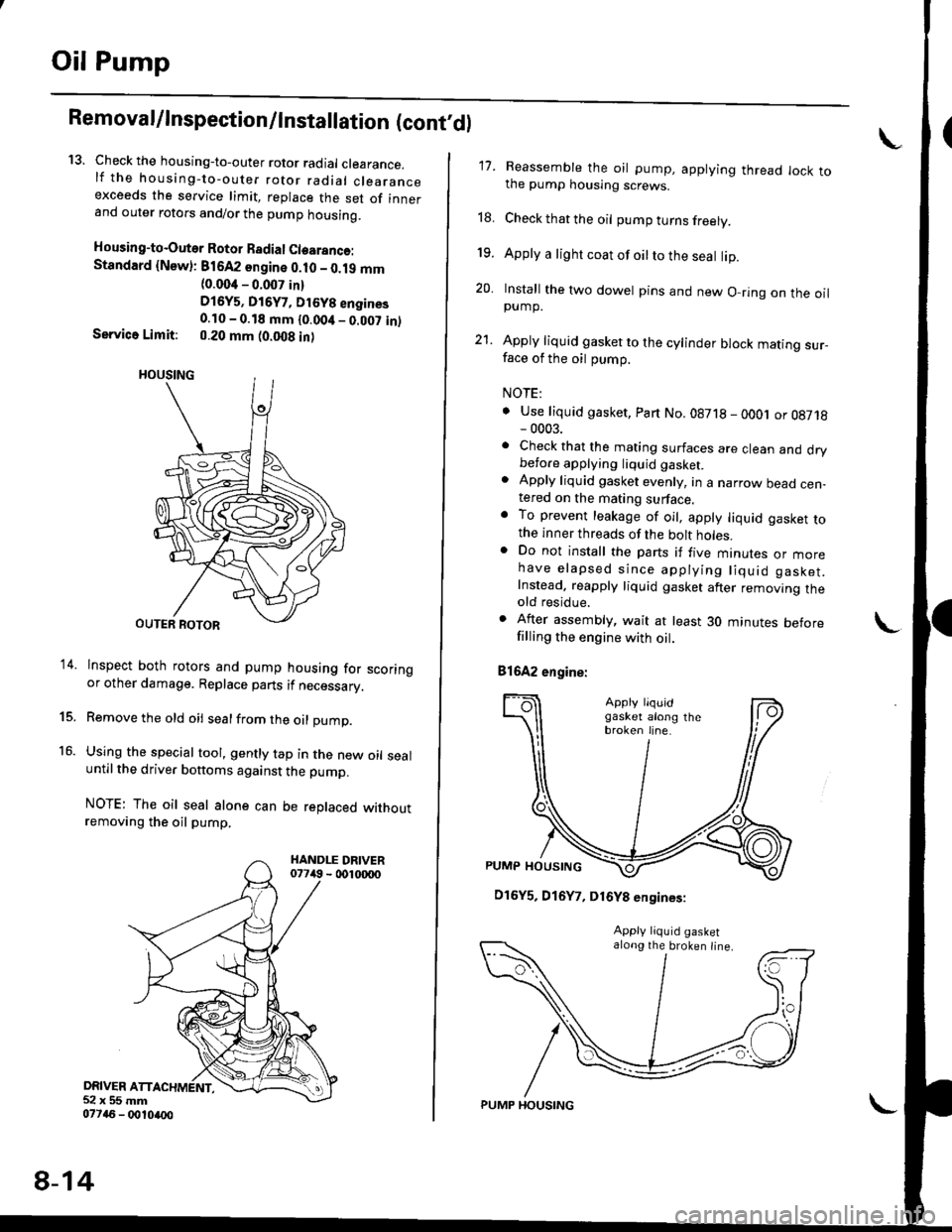
13. Check the housing-to-outer rotor radial clearance.lf the housing-to-outer rotor radial clearanceexceeds the service limit, replace the set of innerand outer rotors and/or the pump housing.
Housing-to-Outer Rotor Badial Clearanco:Standard {Newl: 816A2 sngine 0.10 - 0.19 mm(0.004 - 0.007 in)
D16y5, Di6y7, Dt6y8 engines0.10 - 0.18 mm {0.00it _ 0.007 in)Service Limit: 0.20 mm (0.008 in)
lnspect both rotors and pump housing for scoringor other damage. Replace parts if necessary.
Remove the old oil sealfrom the oil pump.
Using the special tool, gently tap in the new oil sealuntil the driver bottoms against the pump.
NOTE: The oil seal alone can be replaced withoutremoving the oil pump.
DRIVER ATT52x55mm077a6 - 0010ao0
14.
15.
16.
8-14
PUMP HOUSING
17. Reassemble the oil pump, applying thread lock tothe pump housing screws.
18. Check that the oil pump turns freely.
19. Apply a light coat of oilto the seal lip.
20. Install the two dowel pins and new O-ring on the oilpump.
21. Apply liquid gasket to the cylinder block mating sur_face of the oil pump.
NOTE:
. Use liquid gasket, Part No.08718 - oOOj or 08718- 0003.. Check that the mating surfaces are clean and drybefore applying liquid gaskel. Apply liquid gasket evenly, in a narrow bead cen-tered on the mating surface.o To prevent leakage of oil, apply liquid gasket tothe inner threads of the bolt holes.. Do not install the parts if five mtnures or morehave elapsed since applying liquid gasket.Instead. reapply liquid gasket after removing theold residue.
. After assembly, wait at least 30 minutes beforefilling the engine with oil.
81642 engine:
\
D16Y5, D16Y7, D16Y8 engines:
along the broken line.
Page 241 of 2189
22. Installthe oil pump on the cylinder block.
Apply grease to the lip ot the oil pump seal.
Then. install the oil pump onto the crankshaft.
When the pump is in place, clean any excess grease
off the crankshaft and check that the oil seal lip is
not distorted.
81642 engine:
8 x 1.25 mm6x1.Omm
24 N.m (2.i4 kg[.m,17 tbl.trl
11 N.m {1.1 kg{.m,8 rbt ft)O.RI GReplace.
DOWEL PINS
GASKETReplace.
OIL SCREEN
6x1.0mmrl N.m {1.1 kgf'm,I tbf.ftl
D16Y5, D16Y7. D16Y8 enginos:
OOWEL PIN
6x1.0mm11N'm (1.1 kgf m'
O.RINGReplace.
DOW€L PIN
GASKETReplace.
6x1.0mm
6 x 1.0 mm '11 N'm {1 1 kgf'm,
11 N.m (1.1 kgf.m, I lbf ftl
8 lbf.ft)
!o
8-15
lnstall the oil screen.
Install the oil pan (see pages 7-26 or 7-27).
NOTE: Clean the oil pan gasket mating surfaces.
Page 245 of 2189
lntake Manifold
Replacement (cont'dl
NOTE: Use new O,rings and gaskets when reassembling.
CAUTION:
. Check lor folds or scratches on the surface of the gasket.. Replace with a new gasket il damaged.
D16Y8 engine:
INTAKE MANIFOLDReplace if cracked orif mating surfaces areoamageo,
INTAKE AIR CONTROL{ract vAt_vE {M/Tl
GASKETReplace.
8 x 1.25 mm24 N.m {2.{ kgtm.17 tbtftt
THROTTLEBODY
8 x 1.25 mm22 N.rn |.2.2 kgl.rn,16 tbtft)INTAKE MANIFOLDBRACKET
9-4
Page 251 of 2189
Exhaust Pipe and Muffler
Replacement {cont'dl
NOTE: Use new gaskets and self-locking nuts when reassembling.
D16Y8 engine:
MUFFLER
HEAT SHIELD
6x1.0mm9.8 N.m (1.0 kgl m, 7.2 lbf.ft)
EXHAUST PIPE
SECONDARY HO2544 N.m {4.5 kgl.m, 33 lbtftlReplacement, page 9-10
GASKETSReplace.
EXHAUST PIPE A
SELF-LOCKING NUT10 x 1.25 mm54 N.m {5.5 kgl.m, 40 lbtft}Replace.16 N.m {1.6 kgl.m, 12lbf.ft}Replace-
d'*'ou"'"'""'
6x1.0mm9.8 N.m (1.0 ksf m,7.2lbf ft)
8 x 1.25 mm22 N.rn 12.2 kgl.m,16 tbt.ft)Replace.Tighten the bolts insteps, alternatrngside-to-side.
SELF.LOCKING NUT10 x 1.25 mm33 N.m {3.4 kgf.m,25 tbtftlReplace.
TWCinspection, page 9-12
I x 1-25 mm22 N m (2.2 kgf.m. 16 lbfft)
Tighten the bolts in steps,alternating side'to sade.e)GASKETHeplace.
9-10
Page 253 of 2189
TWCHO2S
Inspection
l. Using a flashlight, make a visual check for plugging,
melting and cracking of the catalyst.
D16Y5, D16Y7 engines:
816A2, D16Y8 engines:
-\6{-)\
lT
a
A
FLASHLIGI{T
9-12
Replacement
Primary HO2S:
1. Remove the primary HO2S.
D16Y5, D15Y7 engines:
a. Disconnect the primary HO2S connector, thenremove the cover.
8 x'1.25 mm24 N.m {2.4 kgl.m,
PRIMARY H02SCONNECTOR
b. Remove the primary HO2S.
| \l ,l(
I bK/l
l llw.
/
(
PBIMARY HO2S44 N m (4.5 kgf.m, 33 tbI.ft)