Page 125 of 2189
Valve Seals
Replacement (Cylinder head removal not requiredl
NOTE: Cylinder head removal is not required in thisprocedure.
The procedure shown below applies when using the in-
car valve spring compressor (Snap-on YA884S withY48845 - 2 A7/8" attachment).
!@@ Alway wear approved eye protection whenusing ihe in-cai valve spring compressor.
1. Turn the crankshaft so that the No. I and the No. 4pistons are at top dead center (TDC).
2. Remove the cylinder head cover and the rocker arm
assembly.
NOTE:
. Refer to page 6-30 for rocker arm assembly
removat.
. When removing or installing the rocker armassembly, do not remove the camshaft holder
bolts. The bolts will keep the holders, springs
and rocker arms on the shaft.
. Refer to page 6-46 when installing the cylinder
head cover.
Remove the fuel injectors and the wire harness.
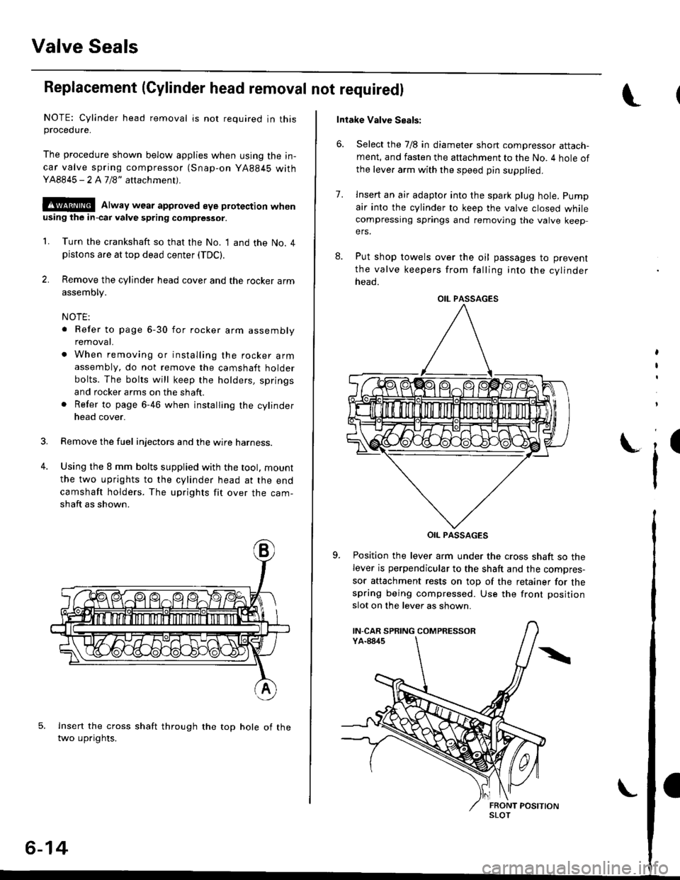
Using the 8 mm bolts supplied with the tool. mount
the two uprights to the cylinder head at the end
camshaft holders. The uprights fit over the cam-
shaft as shown.
lnsert the cross shaft through the top hole of thetwo uprights.
3.
4.
6-14
Intake Valve Seals:
6. Select the 7/8 in diameter short compressor attach-ment, and fasten the attachment to the No. 4 hole of
the leve. arm with the speed pin supplied.
8.
7.lnsert an air adapto. into the spark plug hole. pump
air into the cylinder to keep the valve closed whilecompressing springs and removing the valve keepers.
Put shop towels over the oil passages to prevent
the valve keepers from falling into the cylinder
neao.
OIL PASSAGES
Position the lever arm under the cross shaft so thelever is perpendicular to the shaft and the compres-
sor attachment rests on top of the retainer for thespring being compressed. Use the front position
slot on the lever as shown.
,
I
i'
OIL PASSAGES
IN-CAR SPRING COMPRESSOR
SLOT
Page 126 of 2189
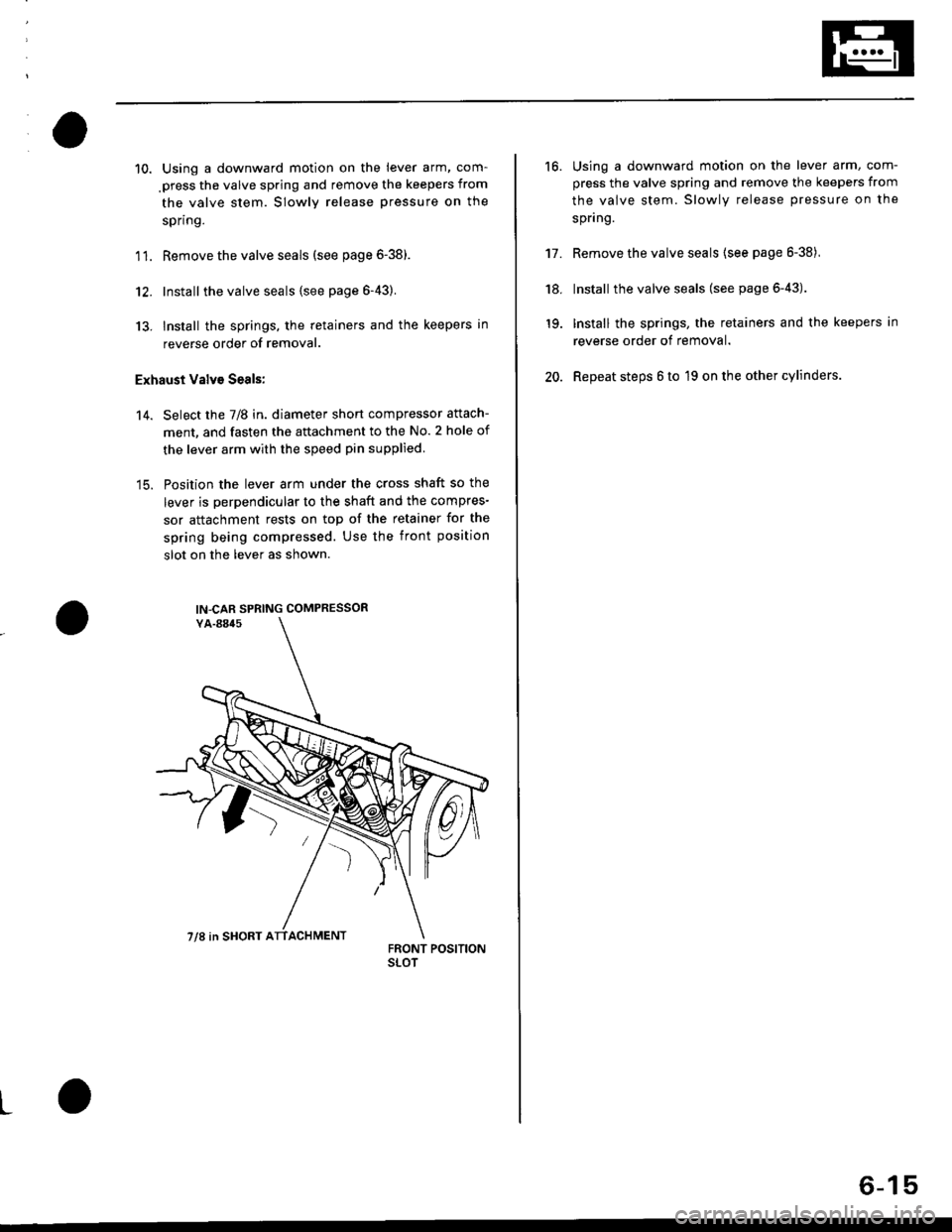
10. Using a downward motion on the lever arm, com-
.press the valve spring and remove the keepers from
the valve stem. Slowly release pressure on the
spring.
11. Remove the valve seals (see page 6-38).
12. Install the valve seals {see page 6-43).
13. Install the springs, the retainers and the keepers in
reverse order of removal.
Exhaust Valvs Sesls:
Select the 7/8 in. diameter short compressor attach-
ment, and fasten the attachment to the No. 2 hole of
the lever arm with the speed pin supplied.
Position the lever arm under the cross shaft so the
lever is perpendicular to the shaft and the compres-
sor attachment rests on top of the retainer for the
spring being compressed. Use the front position
slot on the lever as shown.
'14.
IN-CAR SPRING COMPRESSOR
7/8 in SHORT ATTACHMENT
L
16.Using a downward motion on the lever arm, com-
press the valve spring and remove the keepers from
the valve stem. Slowly release pressure on the
spnng.
Remove the valve seals {see page 6-38),
Install the valve seals (see page 6-43).
Install the springs, the retainers and the keepers in
reverse order of removal.
Repeat steps 6 to 19 on the other cylinders.
't7.
'18.
19.
20.
6-15
Page 128 of 2189

Timing Belt
Illustrated lndex
NOTE:
. Refer to page 6-20 for how to position the crankshaft and pulley before installing the belt.
. Mark the direction of rotation on the belt before removing.
a Do not use the upper cover and lower cover for storing removed items,
. Clean the upper cover and lower cover before installing.
. Replace the ca mshaft seals and cra n kshaft sea ls if there is oil leakage.
. Refer to page 6-16 before installing the timing belt.
CYLINDER HEADCOVERReler to page 6-46when installing.
HEAD COVEB GASKETReplaco when l6akin9,domaged or deteriorated.Apply liquid gasket at
th€ lour corners of thetecessos.
d
@
TIMING BELTInspection, page 6-18Adjustment, page 6-18Removal, page 6-19Installation. page 6-20
I x 1.25 mm3t N.m {3.8 kgf'm, 27 lbfftl
Apply engine oilto the bolt
thleads.
CRANKSHAFT SPEED FI.UCTUATION
lcr(Fl sENsoRReplacement, Page 6-22
UPPER COVEB
lnstallwithsurface facing in.
TIMING BELTDRIVE PULLEYReplacement, page 6_16
6x1.0mm9.8 N'm 11.0 kgt m,7.2 tbf.ft)NUBBER SEALSReplace when damagedor deledorated.
LOWER COVER
FUBBERPLUG
CRANKSHAFT PULLEYReplacement, page 6'16
PULLEY BOLTlil x 1.25 mm20 N.m 12.0 kgt.m,14 lbt'ft) + 90"Replacement, page 6'16Do not us6 an impactwrench when installing.
x 1.0 mmBOLT o-RING10 x 1,25 mm Reolace.14 N.m {,1.5 kgt m, 33 lbt ftl
6x1.0mmt2 N.m 11.2 kgf'm,8.7 tbt f0
9.E N'm (1.0 kgt.m,?.2 tbf.ftl\.-,o
6-17
Page 133 of 2189
Crankshaft Speed Fluctuation (CKF) Sensor
2.
3.
5.
Replacement
4.
1.
6x1.0mm'12 N.m {1.2 kgt.m,8.7 tbf.ft)
6. Installthe CKF sensor in reverse order of removal.
Remove the cylinder head cover.
NOTE: Refer to page 6-46 when installing.
Remove the crankshaft pulley (see page 6_16),
Remove the upper cover and dipstick/tube {seepage 6-19).
Remove the lower cover and idler pulley bracket(see page 6-19).
Disconnect the CKF sensor connector, then removethe CKF sensor.
CKF SENSORCONNECTOR
6-22
:(
I
Page 138 of 2189

Removal
Engine removal is not required for this procedure
!!!s@ Make sure iacks and salety stands are
f ta"eata"ea propetty and hoist brackets are attached to the
correct positions on the engine.
CAUTION:
. Use tender covels to avoid damaging painted sul-
faces.
o To avoid damage, unplug the wiling connectors
carefully while holding the connector portion to
avoid damage.
. To avoid damaging the cylinder head, wait until the
engine coolant temperature drops below 100"F
{38"C} before loossning the tetaining bolts.
NOTE:
o Mark all wiring and hoses to avoid misconnectlon
Also, be sure that they do not contact other wiring or
hoses, or interfere with other parts.
. Inspect the timing belt before removing the cylinder
h ead.
. Turnthe crankshaft pu lley so that the No. lpistonisat
top dead center (see Page 6-21)
'1. Disconnect the negative terminal from the battery'
Drain the engine coolant (see page'10-7).
a Remove the radiator cap to speed draining.
Remove the intake air duct and air cleaner housing
(see page 5 3).
Remove the mounting bolt and lock bolt. then
remove the power steering (P/S) pump belt and
pump (see page 5'5).
Loosen the idler pulley center nut and adjusting
bolt' then remove the air conditioning (A'lc) com-
pressor belt (see Page 5-6).
Loosen the mounting nut and lock bolt. then
remove the alternator belt (see page 6-19).
Remove the P/S pump bracket (see page 5-12).
3.
4.
2.
6.
1.
8. Remove the throttle cable by loosening the locknut,
then slip the cable end out of the throttle linkage
NOTE:
. Take care not to bend the cable when removing it
Always replace any kinked cable with a new one
. Adjust the throttle cable when installing (see sec-
tion 1 1).
D16Y7 engine:
Dl6Y5, Dl6Y8 engines:
THFOTTLECABLE
(cont'd)
6-27
LOCKNUT
CABLE
Page 161 of 2189
VTEC Control SYstem
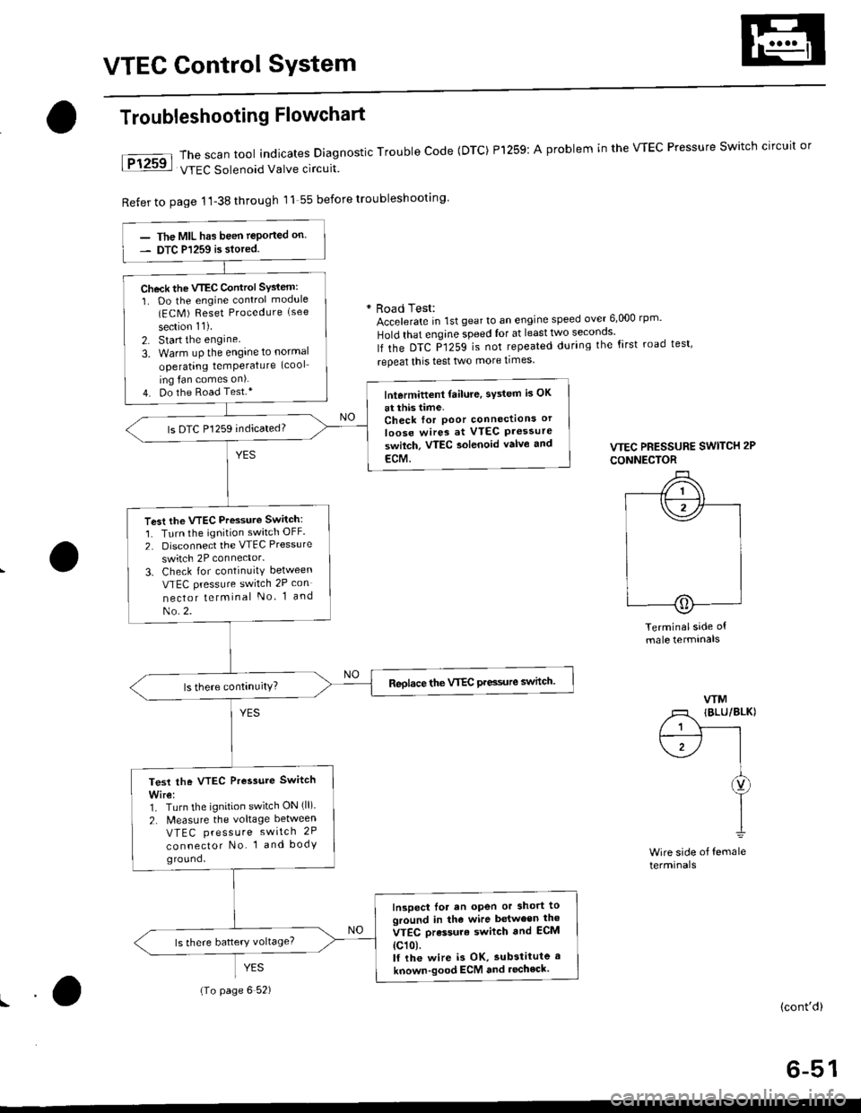
The scan tool indicates Diagnostic Trouble Code {DTC) Pl259:
VTEC Solenoid Valve circuit
Refer to page 1'l-38 through 11 55 before troubleshooting
Troubleshooting Flowchart
YES
A problem in the WEC Pressure Switch circuit or
* Road Test:Accelerate in 1st gear to an engine speed over 6,000 rp '
Hold that engine speed for at leasttwo seconos'
lf the DTC P1259 is not repeated during the first road test'
repeat this test two more times
VTEC PRESSURE SWITCH 2P
CONNECTOR
Terminalside ofmale termtnals
WM
/1 IBLU/BLKI
/ 1 Y------rt--------- l I
\1-/ |I
I
I1
Wire side of femaleterminals
(cont'd)
6-51
The MIL has been teported on.
DTC P1259 is siored.
Check the VTEC Control SYsiem:
1. Do the engine control module(ECM ) Reset Procedure (see
section 11).
2. Start the engine
3. Warm uP the engine to normal
operating temPerature (cool
ing fan comes on).
4. Do the Road Test.*lntermittent failure, sYstem is OK
at this time.Check for Poor connectlons or
loose wires at VTEC Pressureswilch. VTEC aolenoid valvo and
ECM.
ls DTC P1259 indicated?
Test the VTEC Pressure Switch:
1. Turn the ignition switch OFF.
2. Disconnect the VTEC Pressure
switch 2P connector.
3. Check for continuity between
VTEC pressure switch 2P con
nector telminal No 1 and
No.2.
Reolace the VTEC Pre3sure switch.
Test the VTEC Pressure Switch
Wire:1. Turn the ignition switch ON (ll).
2. N4easure the voltage between
VTEC press u re switch 2P
connector No. 1 and bodyground,
Inspect lor an open or short toground in the wire between the
VTEC orassure swilch and ECM
{c101.lf the wire i3 OK, substitute a
known-good ECM and recheck.
{To page 6 52)
Page 162 of 2189
VTEC Control System
Troubleshooting Flowchart (cont,d)
VTEC PRESSURE SWITCH 2PCONNECTOR
Wire side of temaleterminals
OIL PRESSURE GAUGE(Comm.rcially avail.bte)
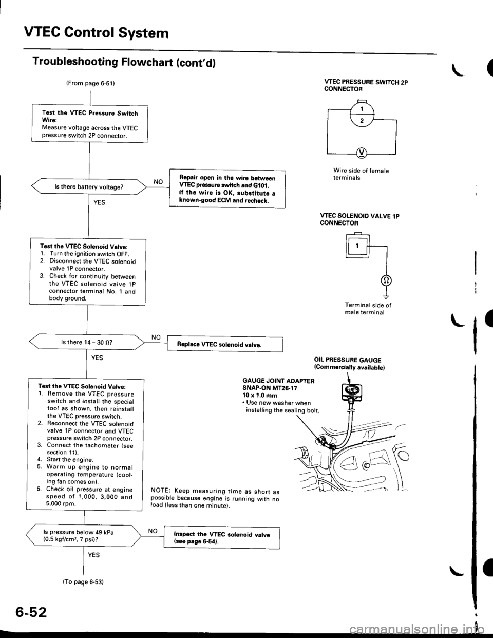
GAUGE JOINT ADAPTERSNAP.ON MT26.1710 x 1.0 ftm. Use new washer wheninstalling the sealing bott.
NOTE: Keep measuring time as shorr aspossible because engine is running witn noload lless than one minute).
6-52
(
VTEC SOLENOID VALVE lPCONNECTOF
Ir------r I
lLl.ll-r
II
It
Terminal side ofmale terminal
I
(From page 6-5l l
(To page 6-53)
Test tha VTEC P.es3uro SwitchWi.e:Measure voltage across the VTECpressure switch 2P connector.
Ropair opon in the wiro batwoenVIEC pr...urc switch and G lot .lf the wiro is OK, 3ubltitutr aknown-good ECM and rochack.
ls there battery voltage?
Test the VTEC Solenoid V.tve:1. Turn the ignition switch OFF.2. Disconnect the VTEC solenoidvalve 1P connector.3. Check for continuity betweenthe VTEC solenoid valve 1Pconnector terminal No, I andbody ground.
ls there 14 - 30 O?
Te3t the VTEC Sotonoid Vatve:'1. Remove the VTEC pressureswitch and install the specialtool as shown. then reinstallthe VTEC pressure switch.2. Reconnect the VTEC solenoidvalve 1P connector and VTECpressure switch 2P connector,3. Connect the tachometer (seesection 1l).4. Start the engine.5. Warm up engine to normaloperatrng temperature (cool-ing fan comes on).6. Check oil pressure at enginespeed of 1,000,3,000 and5,000 rpm.
ls pressure below 49 kPa(0.5 kgflcm,,7 psi)?Inipoct thg VTEC aolenoid valvel3ee P8go 6-54).
I
Page 163 of 2189
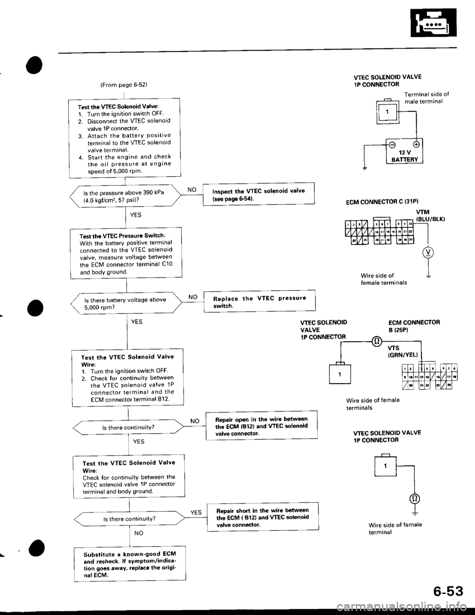
(From page 6-52)
Test the VTEC Solenoid Valve:
1. Turn the ignition switch OFF
2. Disconnect the VTEC solenoid
valve 1P connector,
3. Attach the batterY Posrtrveterminal to the VTEC solenoid
valve terminal.4. Start the engine and check
the oil Pressure at engine
speed ol5,000 rPm
lrcoect the VTEC solenoid valve(see page S54)ls the pressure above 390 kPa(4.0 kgt/cm?, 57 Psi)?
Test the VTEC Pressure Switch:
With the battery Positive terminal
connected to the VTEC solenoid
valve, measure voltage between
the ECM connector terminal C10
and body ground.
ls there battery voltage above
5,000 rpm?
Test the VTEC Solenoid Valve
Wire:1. Turn the ignition switch OFF
2. Check for continuitv between
the VTEC solenoid valve 1P
con nector terminal and the
ECM connector terminal 812
Repair open in the wire between
the ECM lB12| and VTEC aolenoid
Test lhe VTEC Solenoid Valve
Wire:Check for continuity between the
VTEC solenoid valve'lP connector
terminal and body ground.
Repair short in the wiro b€'tween
the ECM ( 812) and VTEC aolenoid
Substitute a known'good ECM
and recheck. lI sYmptom/indica'tion goes away. repleca the origi-
nal ECM.
VTEC SOLENOID VALVE
1P CONNECTOR
Terminal side ofmale terminal
VIEC SOLENOIDVALVE1P CONNECIOR
ECM CONNECTORB l2sP)
ECM CONNECTOR C (31PI
WM
Wire side ot female
termrnals
VTEC SOLENOID VALVE
1P CONNECTOR
I'ft
I
I
Wire side of female
termanal
6-53