Page 775 of 2189
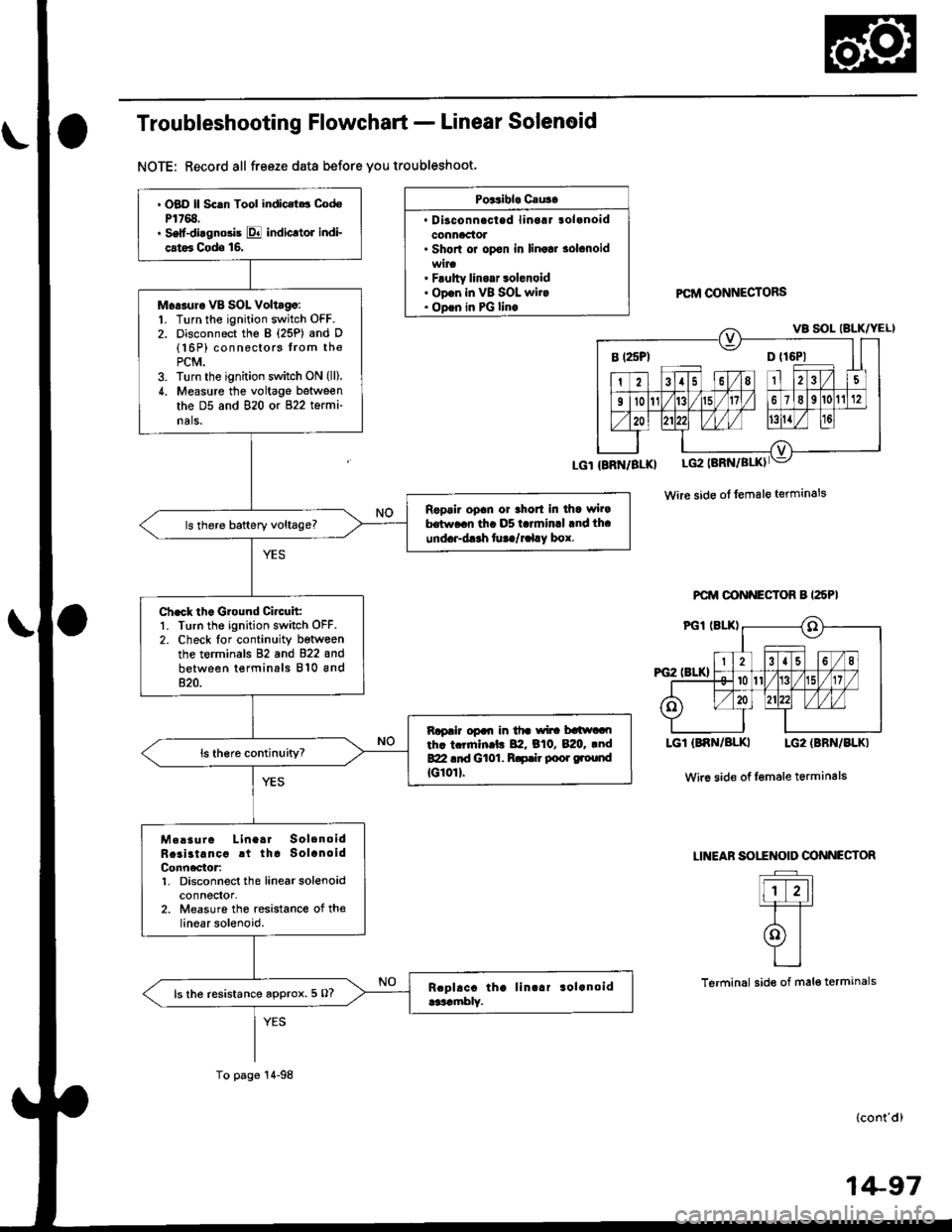
Troubleshooting Flowchart - Linear Solenoid
NOTE: Record all freeze data before you troubleshoot.
Poitibl. Cau3.
. Disconnacted linoaJ tolanoidconnaclol. Shorl or opon in linolr solonoid
. Flulty linoar 3olenoid. ODon in VB SOL wit.. ODen in PG linoPCftI @NNECTORS
Wire side ol female terminals
PCM OONNECTOR B I25PI
LGT (BNN/BLKI LG2 {BBN/BLKI
Wir6 side of Iemale terminals
LINEAF SOITNOID OONNECTOR
Flr-11=T=T
olYI
L_l
Terminal side of mal€ termanals
(cont'd)
B t25Pl D {16P1
. OBD ll Scln Tool indic.t.t CodoP1768.. Self-diagnosis E indicltol indi-
cat6 Cods 16.
Moasur. VB SOL Voltago:1. Turn the ignition switch OFF.2. Disconnect the B {25P) and D(16P) connectors from thePCM.3. Turn the ignition switch ON (lll.
4. Measure the voltage between
the D5 and 820 or 822 termi-
nals.
Ropair opan or thort in dla wi.9hrw..n th. D5 t.rminrl .nd th.
und.r-d.rh fu ta/r.l.y box.
Ch.ck th. Ground Circuit:1. Turn the ignition switch OFF.2. Check lor continuity betwoenthe terminals 82 and 822 and
between terminals 810 and820.
Rapair opal| in tfr wi|! batlwaoth. tcrrnln.l. 82, B10, B:20. .ndBZI .id Gt01. R.p.ir poor ground
tG10rl.
M.!sure Linea. SolenoidRcai3tancc rt tha SolanoidConn6ctor:1. Disconnect the linearsolenoidconnectol,2. Measure the resistance of thelinear solenoid.
ls the resistance approx. 5 O?
To page 14-98
1+97
Page 777 of 2189
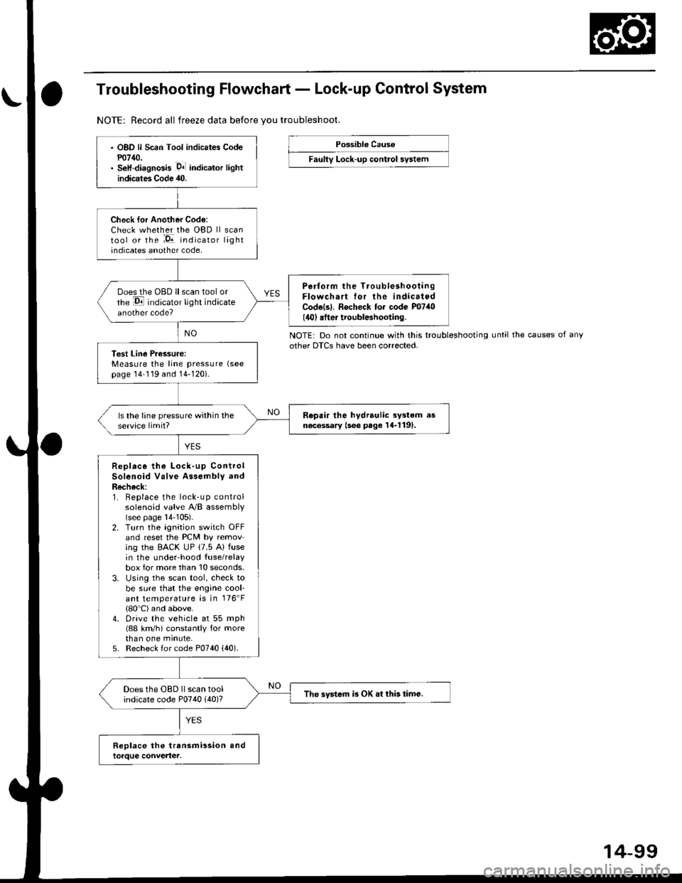
Troubleshooting Flowchart - Lock-up Control System
NOTE: Record all freeze data before vou troubleshoot.
Possibl€ Cause
Faulty Lock-up control sy3tem
NOTE: Do not continue with this troubleshootingother DTCS have been corrected.until the causes of any
OBD ll Scan Tool indicates Codem14/J.S€lf-diagnosis .D4l indicalor lightindicates Code 40.
Check for Another Code:Check whether the OBD ll scantool or the :E indicator lightindicates another code,
Perform the TroubleshootingFlowchart tor the indicatedCodels|. Rocheck to. code P0740(40) .fter troublBhooting.
ooes the OBD ll scan tool orrhe E indicator light indicateanother code?
Test Line Pressure:Measure the line pressure (see
page 14 119 and 14-120).
Repair the hydrrulic sy3tem asn6c6ssary (see page 14-1191.ls the lane pressure within theservice limit?
Replace the Lock-up ControlSolenoid Valve Assembly andRecheck:1. Replace the lock-up controlsolenoid valve A/B assembly(see page 14-105).2. Turn the ignition switch OFFand reset the PCM by removing the EACK UP (7.5 A) fusein the underhood {use/relaybox for more than 10 seconds.3. Using the scan tool, check tobe sure that the engine cool-ant temperature is in 176'F(80'C) and above.4. Drive the vehicle at 55 mph(88 km/h) constantly for morethan one minute,5. Recheck for code P0740 {40).
Does the OBD ll scan toolindicate code P0740 (40)?The svstem i3 OK .t this time.
14-99
Page 778 of 2189
Electrical Troubleshooting ('99 - 00 Modelsl
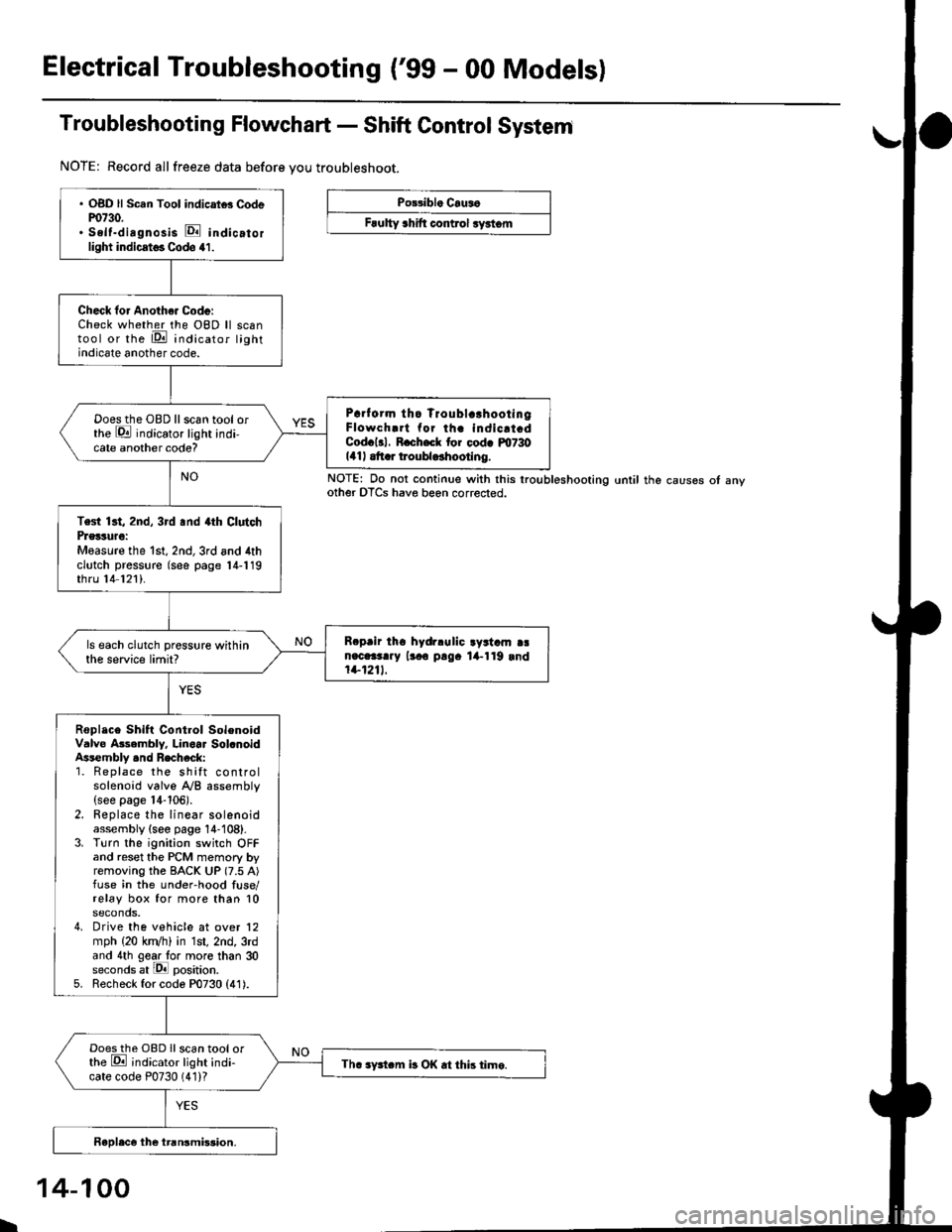
Troubleshooting Flowchart - Shift Control System
NOTE: Record allfreeze data before you troubleshoot.
Po33ibl. Crus6
Frulty 3hift control ryrtom
. OBD ll Scan Tool indicrtd Codem730.. Self-dirgnosis E indicatorlight indicst€. Codo 41.
Check for Anoth€. Code:Check whether the OBD ll scantool or the E indicator lightindicate another code.
Prrf orm tho Troublc!hootingFlowch.rt for th. indicrt.dCod.l3l. R.ch.ck tor cod. m730141| .tt r troubldhootlng.
Doesthe OBD llscan tool orthe E indicator light indi-cate another code?
Test 13t, 2nd, 3rd .nd 4th ClutchPrglture:Measure the 1st, 2nd,3rd and 4thclutch pressure (see page 14-119thru 14 121).
R.prir tho hydrlulic ayrtam aan.c.3t..y lr.o p!9. lil-119 rnd1+1211.
ls each clutch pressure withinthe service limit?
Roplace Shift Control SolenoidValve Asembly. Linoar Sol.noidAssembly .nd Recheck:1. Replace the shift controlsolenoid valve A/B assembly(see page 14-106).2. Replace the linear solenoidassembly {see page 14-108}.3. Turn the ignition switch OFFand reset the PCM memory byremoving the BACK UP (7.5 A)fuse in the under-hood fuse/relay box for more than 10seconds,4. Drive the vehicle at over 12mph (20 kn/h) in 1st, 2nd, 3rdand 4th gear lo. more than 30seconds at lPll position.5. Recheck for code P0730 (41).
Doesthe OBD Ilscan tool orthe E ;ndicator light indi-cate code P0730 (41)?Th. sFtcm b OK .t this time.
NOTE: Do not continue with this lroubleshooting until the causes ot anyother OTCS have beon corrected.
I
14-100
Page 780 of 2189

Electrical Troubleshooting ('99 - 00 Models)
Troubleshooting Flowchart - E Indicator Light Does Not Come On
FCM CONNECTOR B (25P}
LGl {8RN/ALKI{BRN/8LK}
Wire side ol temale terminals
LGl IBNN/BLK} LG2 {BRN/BLK)
i2t5 6q
910t7
LG2
o) (o
The Pll indicator light does notcome on when the ignitionswitch is fi.st turned ON (ll). lltshould come on for about twoseconda.l
Check the Service Check Con-nector:Make sure the special tool (SCS
Service Connector) is not connect-ed to the service check connector?
ls the specialtool {SCS ServiceConnector) is not connected tothe seNice check connector.
Disconnect the special tool fromthe service check connector andr6check.
Check the Dll lndicator LightiShift to d position.
Check for loose terminal fit in thePCM connecto13. It necessary.sub3titute a known-good PCMand recheck.
Does the @ indicator lightcome on?
Check the Ground Circuit:1. Turn the ignition switch OFF.2. Disconnect the B (25P) con-nector from the PCM.3. Check for continuity betweenthe 820 terminal and bodyground, and between the 822terminal and body ground.
Repair open in the wiresbetween the B20 rnd 822 termi-nals and ground (G101), andrep.ir poor ground (G1011.
Measure Power Supply CircuitVoltage:1. Turn the ignition switch ON {ll}.2. Measure the voltage betweenterminals B1 and 822 andbetween terminals Bg and820.
Repair open or short in the wi.obetween th6 81 and/or 89 termi-nals and the PGM-FI main relav,and between th€ PGM-FI mainr€ley rnd the under-hood tus€/relay box.
To page 14''103
14-102
Page 903 of 2189
TCM Circuit Diagram ('96 - 98 Modelsl
UNDEN. HOOD FUSE]RELAY BOX
UNDER OASHFUSE/RELAY 80X
No. 52 1l5A)
No.4l l80A) No.47 (7.5A)
To t 2v lG1sToP sw T HBR( sw- - rur
A/T GEAR POSITIONINDICATOR
IGNITION COIL
Y
I
i
I
IBI-U
rsl
PARKINGBRAKEswrTcH
V
I
I
I
I
IGRN/REO
,t, I
l
I
IGnN,4,vHT
LT GRN
ELKi BI-U
RED
GRN/BLK
NoTEi if :ro 5V
T :To t2v
cRN ---l F----- GnN
Bru -J F------ 61U
8LK
II
Tl
G401G404
,o IJ'^A'
14-226
Page 911 of 2189
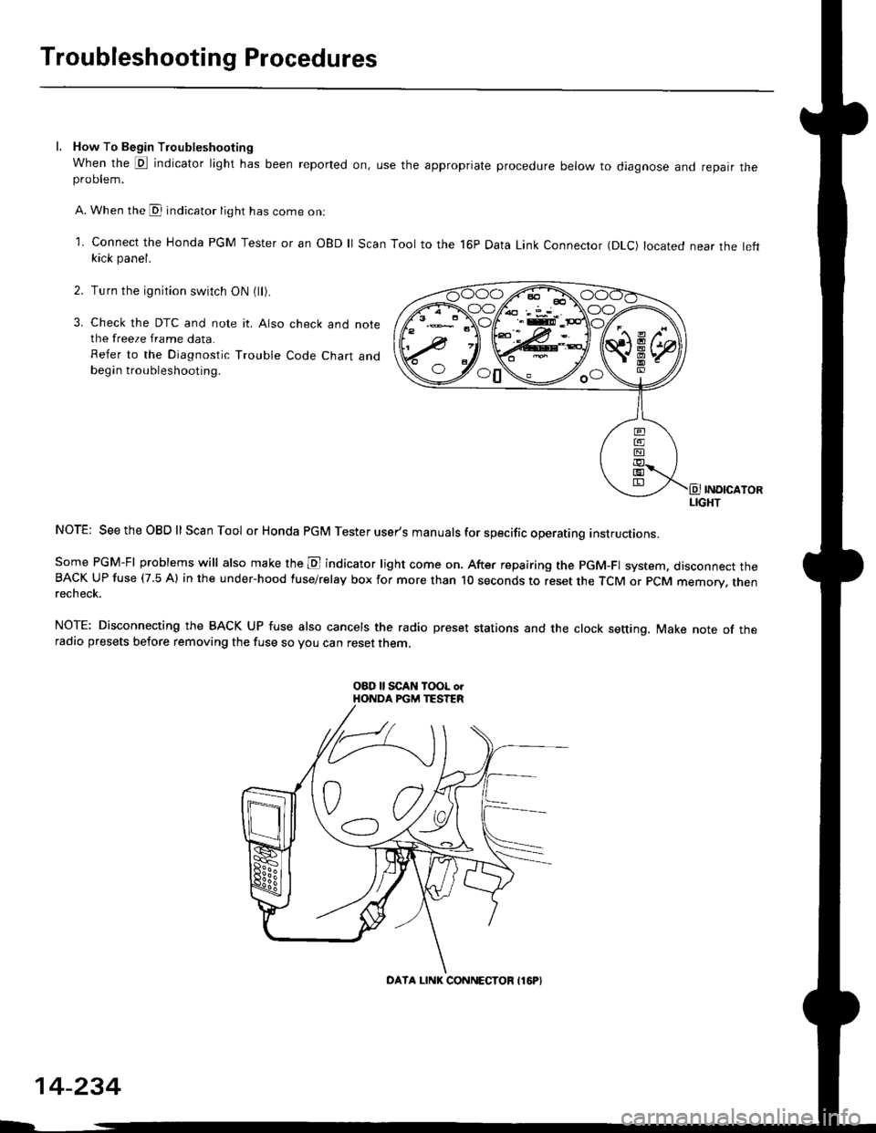
Troubleshooting Procedures
l. How To Begin Troubleshooting
When the E indicator light has been reported on, use the appropriate procedure below to diagnose and repatr theproDlem.
A. When the @ indicator light has come on:
l connect the Honda PGM Tester or an oBD ll Scan Tool to the 16P Data Link Connector (DLc) located near the leftkick panel.
Turn the ignition switch ON (ll).
Check the DTC and note it. Also check and notethe freeze frame data.
Refer to the Diagnostic Trouble Code Chart andbegin troubleshooting.
INOICATORLIGHT
NOTE: SeetheOBDll Scan Tool or Honda PGM Tester user's manuals for specific operating instructions.
Some PGM-FI problems will also make the E indicator light come on. After repairing the pGM-Fl system, disconnect theBACK UP fuse (7.5 Al in the under-hood fuse/relay box for more than l0 seconds to reset the TCM or PCM memory, rnenrecheck.
NOTE: Disconnecting the BACK UP fuse also cancels the radio preset stations and the clock setting. Make note of theradio presets before removing the fuse so you can reset them,
2.
3.
o0\e--loo
OATA LINK CONNECTOB I16P}
14-234
Page 912 of 2189
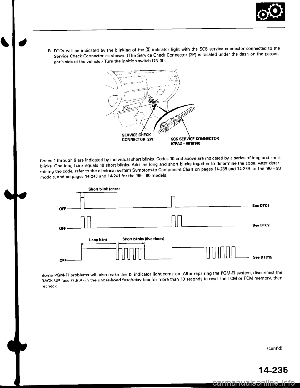
B. DTCS will be indicated by the blinking of the E indicator light with the SCS service connector connected to the
Service Check Connector as shown. (The Service Check Connector (2P) is located under the dash on the passen
ger's side of the vehicle.) Turn the ignition switch ON (ll).
CONNECTOR07PAZ - 00101(x)
codes 1 through 9 are indicated by individual shon btinks. codes 10 and above are indicated by a series of long and short
b|inks.one|ongblinkequa|sloshortb|inks.Addthe|ongandshortb|inkstogethertodeterminethecode.Afterdeter
miningthecode,refertothee|ectrica|systemsymptom-to-componentchartonpagesl4-238and14.239forthe,96_98
models, and on pages 14-240 and 14'241 for the '99 - 00 models
Soc DTCI
Sor DTC2
Long blinkShort blinks |tive tim€sl
some pGM-Ft problems wi
atso make the E indicator light come on. After repairing the PGM-FI system, disconnect the
BACKUPfuse(7.5A)intheUnder.hoodfuse/re|ayboxformorethanl0secondstoresettheTcMorPcMmemory,then
recheck.
Scc DTCI5
(cont'd)
14-235
iii:j
,,,/
CONNECTOR {2PI
Shorl blink (oncc)
Page 914 of 2189
ll. TCM Reset Plocedure
1. Turn the ignition switch off.
2. Remove the BACK Up fuse (7.5 A) from the under-hood fuse/relay box for 10 seconds to reset the TCM or PCM.
NOTE:
. Disconnecting the BACK UPfuse also cancelsthe radio preset stations and the clock setting Make nole ofthe radio
presets before removing the fuse so you can reset them
BACK UPt7.s Al FusE
. The TCM or PCM can also be cleared by using the OBD ll Scan Tool or Honda PGM Tester'
DATA LINK CONNECTOR {16PI
lll. Final Procedut€
NOTE: This procedure must be done after any troubleshooting
'1. Turn the ignition switch off.
2. Reset the TcM or PCM.
3. Disconnect the OBD ll Scan Tool or Honda PGM Tester from the Data Link Connector (16P), or remove the special tool
from the Service Check Connector.
4. Turn the ignition switch ON (ll), and set the radio presets and clock setting.
OBD ll SCAN TOOL o.PGM TESTER
14-237