Page 1455 of 2189

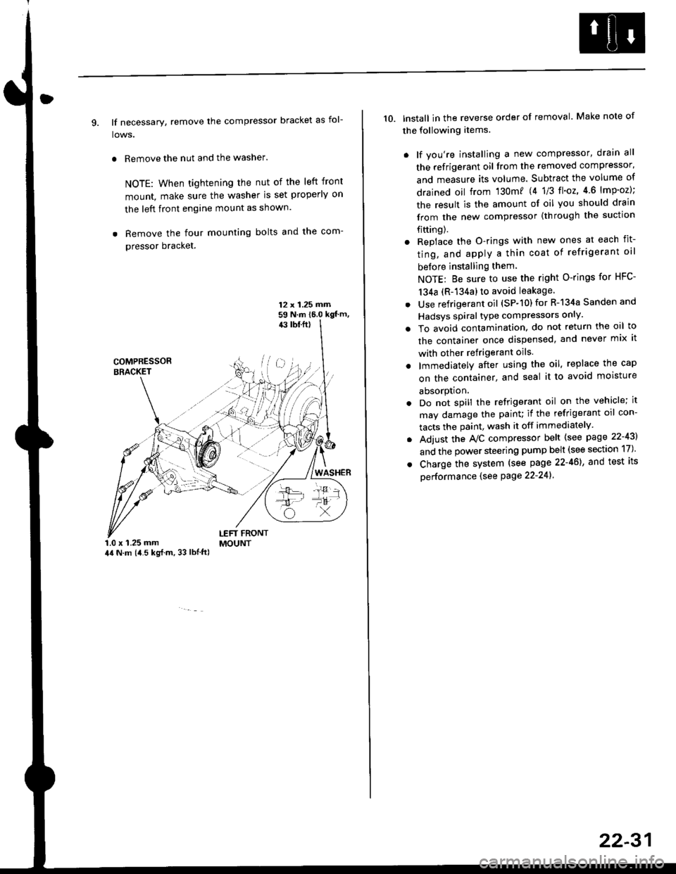
9. lf necessary, remove the compressor bracket as fol-
lows.
. Remove the nut and the washer.
NOTE: When tightening the nut of the left front
mount, make sure the washer is set properly on
the left front engine mount as shown.
. Remove the four mounting bolts and the com-
pressor bracket.
12 x 1.25 rrirn59 N.m 16.0 kgt'm,43 tbf.ft)
COMPRESSORBRACKET
WASHER
1.0 x 1.25 mm44 N.m (i1.5 kg{.m, 33 lbl.ft)
LEFT FRONTMOUNT
10. lnstall in the reverse order of removal. Make note of
the following items.
. lf you're installing a new compressor, drain all
the refrigerant oil from the removed compressor,
and measure its volume. Subtract the volume of
drained oil from '130m? 14 1/3 tl'o2,4 6 lmp'oz);
the result is the amount of oil you should drain
from the new compressor (through the suction
fifting).
. Replace the O-rings with new ones at each fit-
ting, and apply a thin coat of refrigerant oil
before installing them
NOTE: Be sure to use the right O-rings for HFC-
134a (R-134a) to avoid leakage
. Use refrigerant oil (SP-10) for R-134a Sanden and
Hadsys spiral type compressors only'
o To avoid contamination, do not return the oil to
the container once dispensed, and never mix it
with other refrigerant oils.
. lmmediatelY after using the oil, replace the cap
on the container, and seal it to avoid moisture
absorption.
. Do not spill the refrigerant oil on the vehicle; it
may damage the painu if the refrigerant oil con-
tacts the paint, wash it off immediately
. Adjust the Ay'C compressor belt (see page 22-43)
and the power steering pump belt (see section 17)'
. Charge the system (see page 22-46), and test its
oerformance (see Page 22-241
22-31
Page 1462 of 2189

Compressor (DENSOI
Replacement (cont'd)
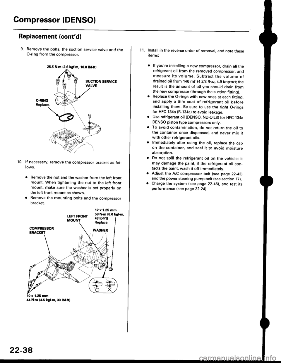
9. Remove the bolts, the suction service valve and theO-ring from the compressor,
lf necessary, remove the compressor bracket as fol-lows.
. Remove the nut and the washer from the left frontmount. When tightening the nut to the left frontmount, make sure the washer is set p.operly onthe left front mount as shown.
a Remove the mounting bolts and the compressor
bracket.
12 x 1,25 rnm59 N.m 16.0 kgfrm,
10.
LEFT FRONTMOUNT€ rbf.fi)Roplace.
WASHEB
x 1.25 mm
2s.5 N.m {2.6 kgf.m. 18.8 tbtttl
4/r N.m {4.5 kgf.m, 33 lbt ft}
22-3A
1 1. Install in the reverse order of removal, and note thesertems:
lf you're installing a new compressor. drain all therefrigerant oil from the removed compressor. andmeasure its volume. Subtract the volume ofdrained oil from '140 ml (4 28 fl{,z, 4.9 lmpoz); theresult is the amount of oil you should drain fromthe new compressor (through the suction fifting).Replace the O-rings with new ones at each fining,and apply a thin coat of refrigerant oil beforeinstalling them. Be sure to use the right O,ringsfor HFC-134a (R-134a) to avoid leakage.
Use refrigerant oil {DENSO, ND-OtL8) for HFC-134aDENSO piston type compressors only.To avoid contamination, do not return the oil tothe container once dispensed, and never mix itwith other refrigerant oils.
lmmediately after using the oil, replace the capon the container, and seal it to avoid moisture
absorption.
Do not spill the refrigerant oil on the vehicle; itmay damage the paint; if the refrigerant oil con-tacts the paint, wash it off immediatelv.
Adjust the ly'C compressor belt (see page 22-43)and the power steering pump belt (see section 17).Charge the system (see page 22-46), and test itsperformance (see page 22-24!..
Page 1476 of 2189
Troubleshooting
Schematic Symbols
BATTERY
E
@
GROGroLrnd terminal
II_d:
UNDComponent ground
II_..'-
FUSE
--cn-.e
COIL, SOLENOID
r{r
tql'|
CIGARETTE LIGHTER
A
lrl
P
RESISTOR
I
f
VARIAELE RESISTOR
ilH
THERMISTOR
c
IGNITION SWITCH
-fo o.t-
BULB
+
HEATEB
At-l
F
MOTOR
0
PUMP
H
CIRCUIT BREAKER
I
r
Yr
T
HORN
+
DIODE
+
SPEAKER, BUZZER
D
Mast
Y
ANTt:f\,NATRANSISTOR lTrl
II
SWITCH (ln niNormally open
I
/F\t tL I\Y/
I
rrdal positionlNormally closed'*i."n
@
I
LIGHT EMITTINGDIODE ILEDI
A+,
TT
RELAY lln noNormally opon relay
| ....--1'rl*r
til
t "t^f
fmal poaitionlNormally closed relay
ffl-+- |
lrl
lrl
fff
CONDENSER
I
T
CONNTInput
V
I
:CTIONOutput
J
CONNECTOR
*>-
'l!
REED SWITCH
A
tftl
Y
Page 1835 of 2189

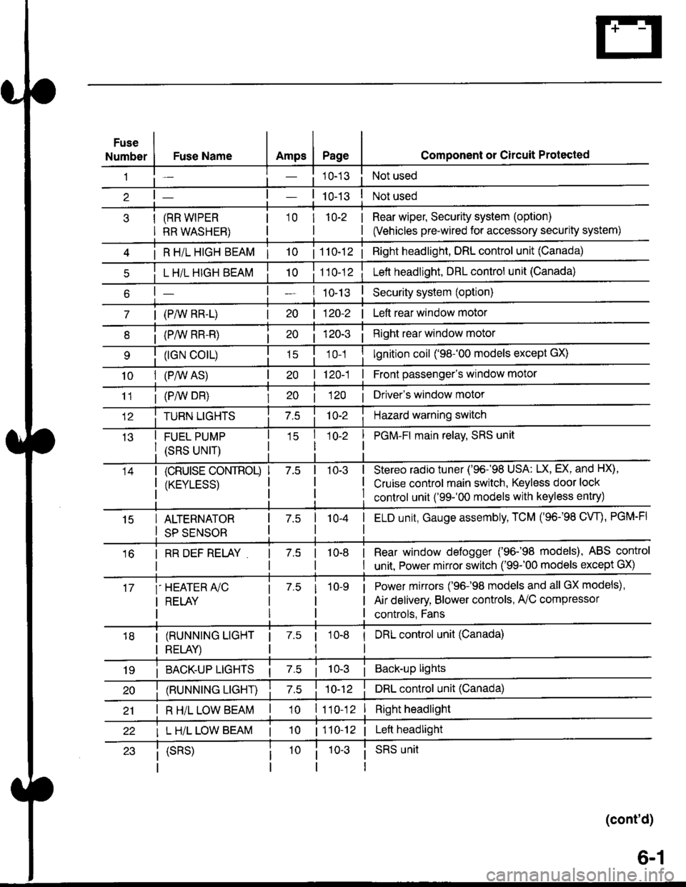
Fuse
NumberAmpsPageFuse Name
(RR WIPER
RR WASHER)
i R HiL HIGH BEAM | 10
L H/L HIGH BEAM
| (PAIV RR-L)
i (P/vv RR-R)
(rGN CO|L)
10I (P,^/V AS)
Component or Circuit Protected
Not used
Not used
Rear wiper, Security system (option)
(Vehicles pre-wired for accessory security system)
'10r 1n-2
I
| 1 10-12i Right headlight, DRL control unit (Canada)
Lett headlight, DRL control unit (Canada)
I ro-rsSecurity system (option)
| 120-2 | Left rear window motor
Right rear window motor
lgnition coil ('98-'00 models except GX)
| 120-1 | Front passenger's window motor
i (PiW DH)| 20 1 12O I Driver's window motor
TURN LIGHTSHazard warning switch
FUEL PUMP
(SRS UNIT)
PGM-FI main relav, SRS unit
(cRUrsE CoNTROL)
/KtrVt trSS\
Stereo radio tuner ('96-'98 USA: LX, EX, and HX),
Cruise control main switch, Keyless door lock
control unit ('99-'00 models with keyless entry)
15ALTERNATOR
SP SENSOR
l-a10-4I ELD unit, Gauge assembly, TCM (96-'98 CW, PGM-FI
16I RR DEF RELAY7.510-8I Rear window defogger ('96-'98 models), ABS control
I unit. Power mirror switch ('99-'00 models except GX)
i-HEATER r/C
I RELAY
Power mirrors ('96-98 models and all GX models),
Air delivery, Blower controls, AilC compressor
controls, Fans
I (RUNNING LIGHT
I RELAY)
1 7.5 1
tl
I DRL control unit (Canada)
i BACK-UP LTGHTSi Back-up lights
(RUNNING LIGHT)DRL control unit (Canada)
I R H/L LOW BEAM'10 l11o-12Right headlight
I L H/L LOW BEAM | 101110-12 | Left headlight
(cont'd)
(SRS)SRS unit
6-1
Page 1841 of 2189

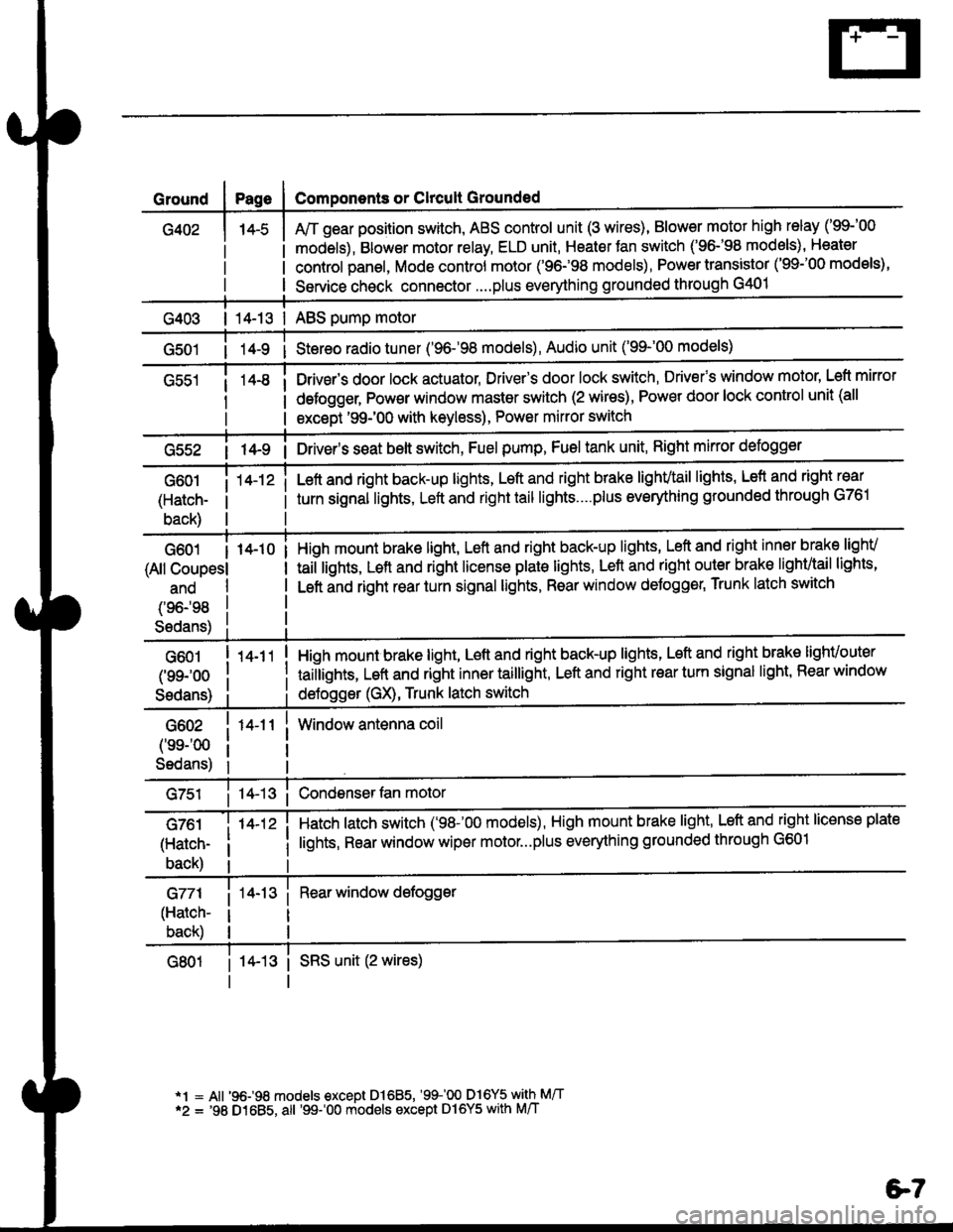
Ground
G402
Components or Clrcult Grounded
Arr gear position switch, ABS control unit (3 wires), Blower motor high relay ('99-'00
models), Blower motor relay, ELD unit, Heater Jan switch ('96-'98 models), Heater
control panel, Mode control motor ('96.�98 models), Power transistor ('99-'00 models),
Service check connector....plus everything grounded through G401
| 14-13 | ABS pump motor
1l-9 i Stereo radio tuner ('96-'98 models), Audio unit ('99-'00 models)
Drivsr's door lock actuator, Driver's door lock switch, Drivefs window motor' Left mirror
defogger, Pow€r window master switch (2 wires), Power door lock control unit (all
except '99-'00 with keyless), Power mirror switch
G55214-9 i Driver's s€at belt switch, Fuel pump, Fuel tank unit, Right mkror defogger
G601
(Hatch-
back)
14-12 iLeft and right back-up lights, Left and right brake lighvtail lights, Lefl and right rear
turn signal lights, Left and right tail lights....plus eveMhing grounded through G761
G601 I 14-10
(All Coupesl
ano
(96198
S6dans)
High mount brake light, Left and right back-up lights, Left and right inner brake lighv
taiilights, Lett and right license plale lights, Lett and right outer brak€ lighvtail lights'
Left and right rear turn signal lights, Rear window deJogger, Trunk latch switch
G601
(99-'oo
Sedans)
G602
('ss-'00
Sedans)
G761
(Hatch-
back)
G771
(Hatch-
back)
14-11
14-12 i
High mount brake light, Left and right back-up lights, Left and right brake lighvouter
taillights, Left and right inner taillight, Left and right rear turn signal light' Rear window
deJogger (GX), Trunk latch switch
Window antenna coil
Hatch latch switch ('98-'00 models), High mount brake light' Left and right license plate
lights, Rear window wiper motor...plus everything grounded through G601
Rear window defogger
14-13 i SRS unit (2 wires)
*1 = All '96-98 models €xcept Dl685, '99100 D16Y5 with M/T*2 = '98 D1685, all '99-'00 models except Dl6Y5 with M/T
e7