Page 424 of 2189
Secondary Heated Oxygen Sensor (SecondarytlO2S) (Sensor 2l
('99 - 00 lilodels except DtGYS engine with M/T)
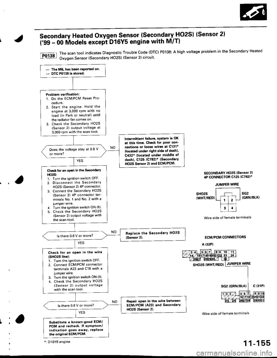
The scan tool indicates Diagnostic Trouble code (DTC) P0138: A high voltage problem in the secondary Heated
Oxygen Sensor (Secondary H02S) (Sensor 2) circuit.
SECONDARY HO2S {S€nsot 2}
4P CONNECTOR Cl25 lc782l'
JUMPER WIRE
Ir
sH02s(WHT/RED)sG2{GRN/BLKI
Wire side of female termanals
ECM/PCM CONNECTORS
A (32P1
Wire side ot female termlnals
gs92g 111yp17p5py | .lutuPea wtne
- The MIL has beon reportod on.- DTC m138 is.tored.
Ploblem vorification:1. Do the ECM/PCN4 Reset Pro-
cedure.2. Start the engine Hold the
engine at 3,000 rpm with no
load (in Park or neutral) until
the radiator{an comes on
3. Check the SecondarY H02S(Sensor 2) output voltage at
3,000 rpm with the scan tool
lntormittont failuio, sYstom b OK
st thir timo. Check for Poor con_
nections ot loo39 wiJo3 af Cl3lr(located under right ride ot desh),
C432' (locatod undot middle of
dashl, Cl25 {C782lr (Secondaiy
HO2S Son3or 2l and ECM/PCM.
Does the voltage stay at 0 6 V
or more?
Ct€d( tor an opan in the Secondary
l|o2s:1. Turn the ignition switch OFF
2. Disconnect the SecondarY
HO2S (Sensor 2) 4P connector.
3. Connect the Secondary HO2S(Sensor 2) 4P conneclor ter_
minals No. 1 and No.2 with a
iumper wire.4. Turn the ignition switch ON (ll)
5. Check the SecondarY HO2S
lSensor 2) outptlt voltage with
the scan tool,
lsthere 0.6 V or more?
Check lor an open in the wiro(SHO2S line):1. Turn the ignition switch OFF.
2. Connect ECM/PCM connector
terminals A23 and C18 with ajumper wrre,
3. Turn the ignition switch ON (ll).
4. Check the SecondarY HO2S
{Sensor 2) outPut vo ltage
with the scan tool.
Repair opon in tho wire betwecn
ECM/PCM (A23) and SocondarY
HO2S {Sansor 2).ls there 0.6 V or more?
Substitut€ a known'good ECM/
PCM and recheck. It symptom/indication goes awey, JePlaco
the otiginel ECM/PCM
*i 016Y8 engine1 1-155
Page 425 of 2189
PGM-FI System
Secondary Heated Oxygen Sensor (Secondary HO2S) {sensor 2l
[FO13a]l The scan tool indic€tes Diagnostic Trouble Code {DTC) P0139: A slow response probtem in the Secondary Heated- Uxygen Sensor (HOzS) (Sensor 2) circuit.
1 1-156
- The MIL has been reported on.- DTC P0139 is stored.
Problem verification:1. Do the ECM/PCM Reset Pro-
2. Start the engine. Hold theengine at 3,000 rpm with noload {in Park or neutral) untilthe radiator fan comes on.3. With the scan tool, check theSecondary HO2S (Sensor 2)output at 3,000 rpm.
Intermiftent failure, system i! OKat this tims. Check for pool con-nections or loos6 wiles at C131.{located undor ght lide of dash),C432' (locrted under middle otd.shl Cl25 (C782lr (SocondaryHO2S) (Sonsor 2) and ECM/FCM.
Does the voltage stay within0.3 - 0.6 V for two minutes?
*: D16Y8 engine
Page 432 of 2189

The scan tool indicates Diagnostic Trouble Code (DTC) Pl167: A system malfunction in the Primary Heated
Orygen Sensor {Primary HO2S) (Sensor 1) Heater circuit
PRIMABY HO2S ISENSOR 1} 8P CONNECTOR
tc145l
ECM CONNECTOR C (31P)
- The MIL has be€n reported on.- DTC Pl167 i3 3tored.
Problem Veritication:1. Do the ECM Reset Procedure.
2. Start the engine. Hold the
engine at 3,000 mm with no
load (transmission in neutral)
until the radiator fan comes
on.Intormittont failure, system i3 OK
at thia time. Chock for Poor con_
noction3 or looso wilgt ai Cl45(Primary HO2S, Son3or 1l andECM.
ls DTC1167 indicated?
Check lor sn open in the wire(VS+ linel:1. Turn the ignition switch OFF
2. Disconnect the Primary HO2S
{Sensor 1) 8P connector.
3. Turn the ignition switch ON (ll).
4. Measure voltage betwe€n thePrimary HO2S (Sensor '1) 8P
connector terminal No 6 and
body ground.
Ch.ck the ECM:Measure voltage between the
ECM connector terminsl C25 and
body ground.
ls there more than 5 V?
Repair opon in the wite ECM (C25)
and P m.ry HO2S (S€n3or 11.ls there more than 5 V?
Replaco the Primary HO2S (Son-
sor 11.Substitute ! known-good ECM
and r6check. lf symptom/indica-tion gos6 away, r.place tho origi'
nd ECM,
,l23458910
111213t415161718
a2125a30
VS+{WHTIWire side of femaleterminals
1 1-163
Page 434 of 2189
t
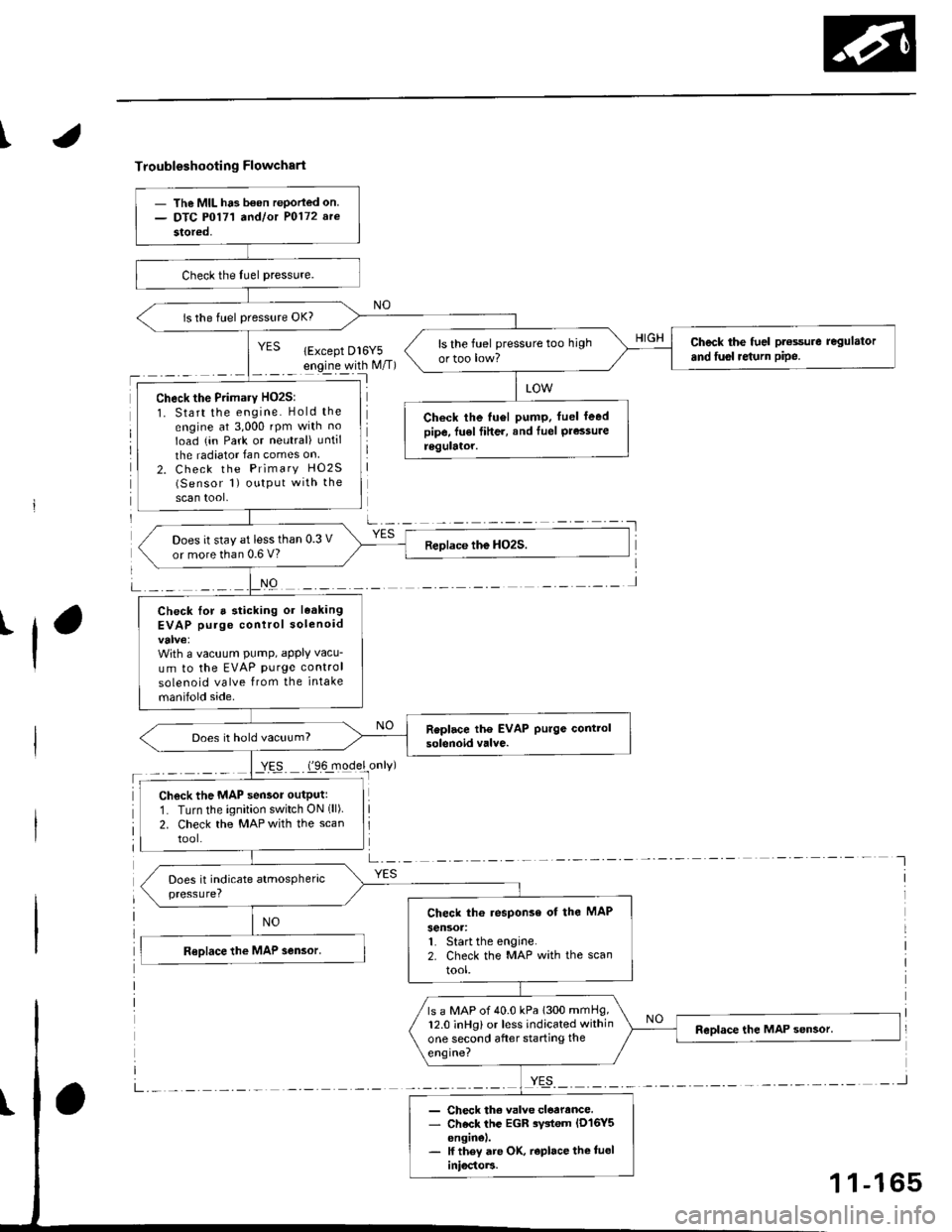
Troubleshooting Flowchart
'l
NO
a-,-:- -
YES
- The MIL ha3 b€on rePorled on.- DTC P0171 a^dlot P0172 arc
stored,
is the fuel pressure OK?
Check the fuel pt€ssure regulator
and fusl re{urn pipe.ls the fuel pressure too high
ortoo low?
Check the Primary HO2S:
1. Start the engine. Hold the
engine at 3,000 rpm with no
Ioad (in Park or neutral) until
the radiator Ian comes on
2. Check the Primary HO2S(Sensor 1) output with the
scan tool,
Check the tu6l pump. fuel leedpipe, fu€l fiher, and Iuel Pressureregulator.
Does it stay at less than 0.3 V
or more than 0.6 V?
Check lor a sticking or leaking
EVAP purge control solenoid
With a vacuum PumP, aPPIY vacu-
um to the EVAP purge control
solenoid valve from the intake
manifold side.
Does it hold vacuum?
Check the MAP sensor outputr
1. Turn the ignition switch ON (ll)
2. Check the MAP with the scan
tool.
Check th6 response of the MAP
sensoa:1. Start the engine.2. Check the MAP with the scan
tool.
ls a MAP of 40.0 kPa 1300 mmHg,12.0 inHg) or less indicated within
one second after starting the
engine?
- Check th€ valve cloarance.- Check the EGR rystem lD16Y5enginel.- lf they are OK, r€place the tueliniocto]3.
1 1-165
Page 439 of 2189
PGM-FI System
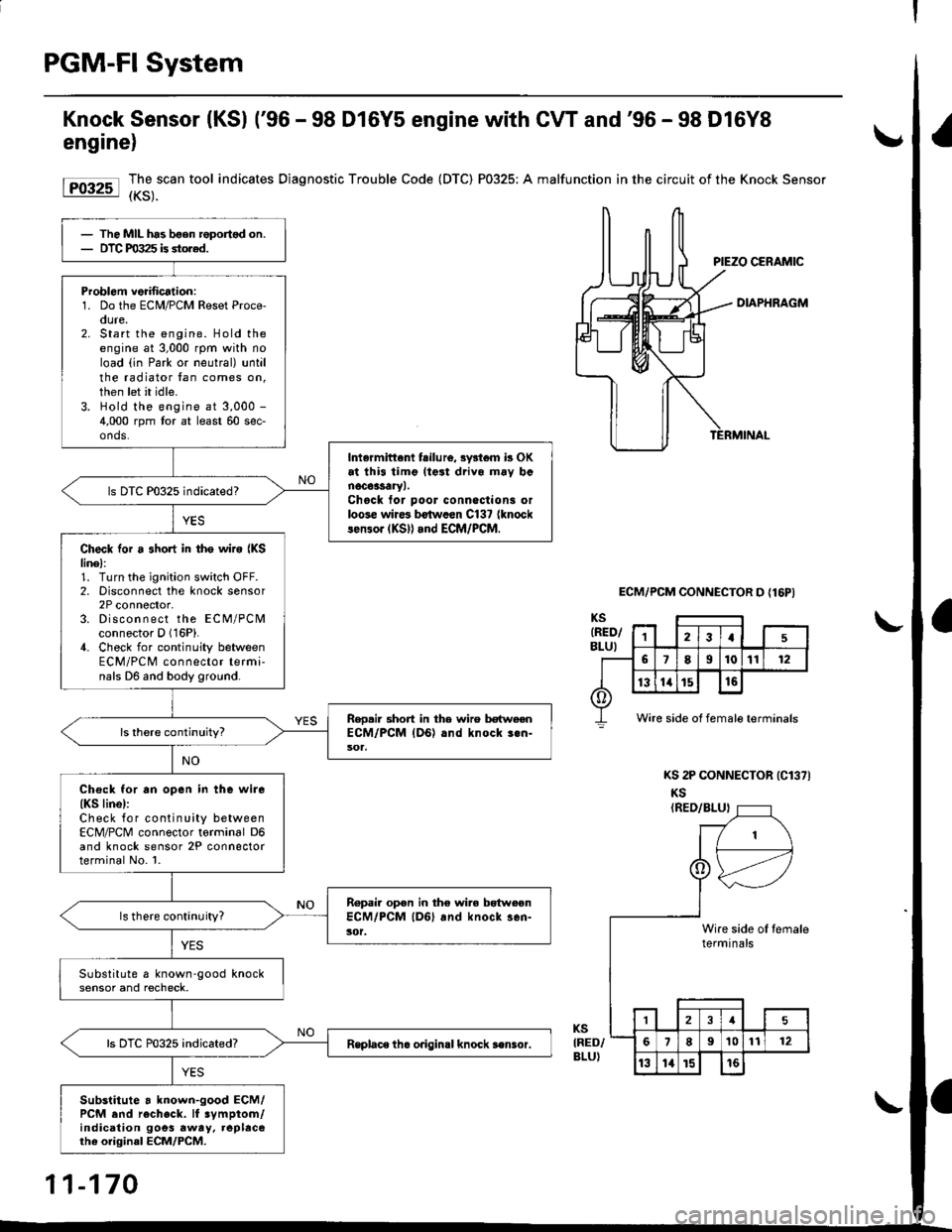
Knock Sensor (KSl ('96 - 98 D16Y5 engine with CW and'96 - 98 D16Y8
engine)
Forr-l I,3,.""""
tool indicates Diagnostic Trouble Code (DTC) P0325: A malfunction in the circuit of the Knock sensor
DIAPHRAGM
ECM/PCM CONNECTOR D {16PI
KS 2P CONNECTOR (Cl371
KS(RED/BLUI
KSIRED/BLU)
The MIL has bgen roportsd on.DTC PO:t25 is stored.
Problom veiilication:1. Do the ECM/PCM Reset Proce-oure,2. Start the engine. Hold theengine at 3,000 rpm with noload (in Park or neutral) untilthe radiator tan comes on,then let it idle.3. Hold the engine at 3,000 -
4,000 rpm tor at least 60 sec-onds.
Intermittenl fsilu16, 3y3l6m b OKat thi3 timg lteat drivo mav banoc63saryl.Chock tor poor conneclioni orloose wire3 b€twccn C137 {knocklen3or (KS)l and ECM/PCM.
ls DTC P0325 indicated?
Check for a short in tho wire {KSlinel:1. Turn the ignition switch OFF.2. Disconnect the knock sensor2P connector,3. Discon n ect the ECM/PCMconnector O (16P).
4. Check for continuity betweenECM/PCM connector termi-nals D6 and body ground.
Reo.ir 3hort in the wire betweenECM/PCM {DG) .nd knock 3.n-
Chock for an open in the wire(KS linel:Check for continuity betweenECM/PCM connector torminal D6and knock sensor 2P connectorterminal No. l.
Ropair open in the wire bgtweonECM/PCM lD6l and knock sen-3('t.ls there continuity?
Substitute a known-good knocksensor and recheck.
Rsplace th. o.igin.l knock s€nsor.
Substitute a known-good ECM/PCM end recheck. lf 3ymptom/indication goes rway, replacerhe original ECM/PCM.
Wire side of female terminals
1\
I
tert
,_-
eslnini
,--tl
le oI temrlsal€
121
189't01t12
13l4t5t6
11-170
Page 440 of 2189
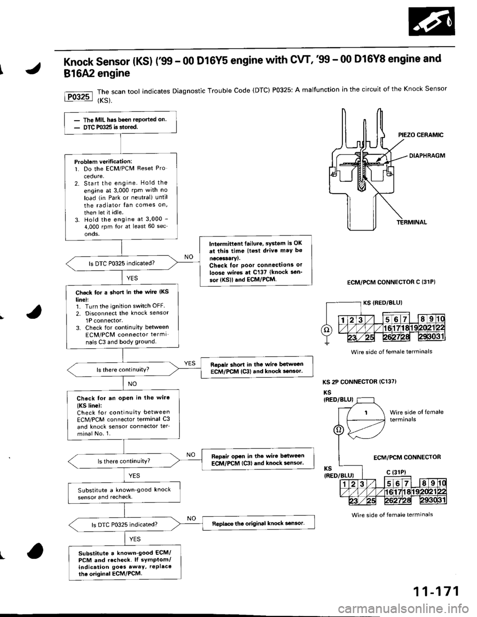
Knock sensor (Ks) r99 - 00 D16Y5 engine with cw, '99 - 00 D16Y8 engine and
816A2 engine
The scan tool indicates Diagnostic Trouble Code (DTC) P0325: A malfunction in the circuit of the Knock Sensor
{KS}.
OIAPHRAGM
ECM/PCM CONNECTOR C (31P)
KS 2P CONNECTOR (C1371
KS
Wire side of female terminals
t
The MIL has been reported on.
DTC m325 is stored
Problem verification:1. Do the ECM/PCM Reset Pro
cedure,2. Start the engine Hold the
engine at 3,000 rpm with no
load (in Park or neutral) until
the radiator fan comes on,
then let it idle.
3. Hold the engine at 3.000 -
4,000 rpm for at least 60 sec'
onds.
lntermittent failure, system is OK
at thi3 time lt€3t drive maY b€
nocessaryl.Chsck tor poor connections or
loose wiros at C137 {knock sen'
sor {KSll and ECM/PCM.
ls DTC P0325 indicated?
Ch€ck for a short in tho wire (KS
linel:1. Turn the ignition switch OFF.
2, Disconnect the knock sensor
1P connector.3. Check for continuity between
ECM/PCM connector termi_
nals C3 and body ground.
Repri. short in the wiro bqtwecnECM/PCM lc3l and knock 3ensor.ls there continuity?
Check for an open in lhe wire
{KS linc):Check for continuity between
ECM/PCM connector terminal C3
and knock sensor connector ter-
minal No. 1.
Replir open in the wire bdtweon
ECM/PCM {Ctl and knock sensor'
SubstitLrte a known'good knock
sensor and recheck,
Replace tho otiginal knock sensor.
substitute a known-good ECM/PCM and recheck. ll symptom/indication goes awaY, rePl6co
tha o.iginal ECM/PCM.
Wire side of female terminals
ECM/PCM CONNECTOR
11-171
Page 447 of 2189

PGM-FI System
Barometric Pressure (BAROI Sensor
The scan tool indicates Diagnostic Trouble code (DTC) Pi106: A range/performance problem in the BaromerrrcPressure (BARO) Sensor circuit.
The scan tool indicates Diagnostic Trouble code (DTc) P1107: A low voltage probtem in the Baro sensor circurr.
The scan tool indicates Diagnostic Troubre code {DTC) p1108: A high vortage probrem in the Baro sensorcircuit.
fF1lot
tPlloal
The MIL ha3 been r€Dortsd on.DTC Pl106 is stored.
Problem verification:1. Do the ECM/PCM reset pro-cedure,2. Start the engine. Hold theengine at 3,000 rpm with noload (in Park or neutral) untilthe radiator fan comes on, thenlet it idle.3. Connect the SCS service connector.4. Test drive with the A/T in Eposition, M/T in 4th gear.5. Accelerate for five secondsusing wide open throttle.
Intormittont tailure, system is OKat this time.ls DTC P1106 indicated?
Substitut€ e known-good ECM/PCM and recheck. ll symptom/indication goes .way, .oplsce theo.iginal ECM/PCM.
The MIL has been .oported on.DTC P'l107 o. Pl108 is stored.
P.oblem veritication:1. Do the ECM/PClvl Reset pro
cedure,2. Turn the ignition switch ON (ll).
Intormittent frilure, syitem i3 OKat this time.ls DTC P1 107 or Pl108 indicated?
Substitute a known-good ECM/PCM and rechock. It symptom/indication goes away, .6placethe original ECM/PCM.
11-178
Page 461 of 2189
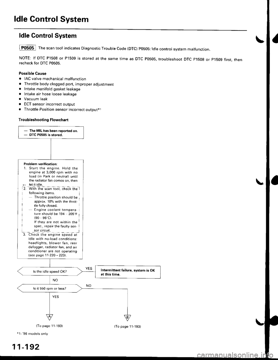
ldle Control System
ldle ControlSystem
lF0505 l Th" """n tool indicates Diagnostic Trouble Code (DTC) PO5O5: tdte controt system malfunction.
NOTE: lf DTC P1508 or P1509 is stored at the same time as DTC P0505, troubleshoot DTC p1508 or p1bog first. thenrecheck for DTC P0505.
Possible Cause
. IAC valve mechanical malfunction
. Throttle body clogged pon, improper adjustment. Intake manifold gasket leakage
. Intake air hose loose leakage
. Vacu um leak
. ECT sensor incorrect output
. Throttle Position sensor incorrect output*r
Troubleshooting Flowchart
The MIL has been reoorted on.DTC P0505 is stored.
Problem verification:1. Start the engine. Hold theeng;ne at 3,000 rpm with noload (jn Park or neutral) untilthe radiator fan comes on, then*r let it idle.t2. with rhe scan toot, ct'eit Ge l
Throttle position should beapprox. 10% with the throttle fully closed.E ngine coolant tempera-ture should be 194 205'F(90 96.Ci.lf they are not within thespec., repair the faulty sen
L._ _9oI9[cr]41 l3. Chec& the engine speed atidle with no-load cond;tionsiheadlights, blower fan, reardefogger, radiator fan, and airconditioner are not operating\see page l1-22O - 223).
Intermittent tailure, system is OKat this time.ls the idle speed OK?
ls it 550 rpm or less?
(To page 11,193)
*1r'96 models only
11-192
(To page ll-193)