Page 790 of 2189

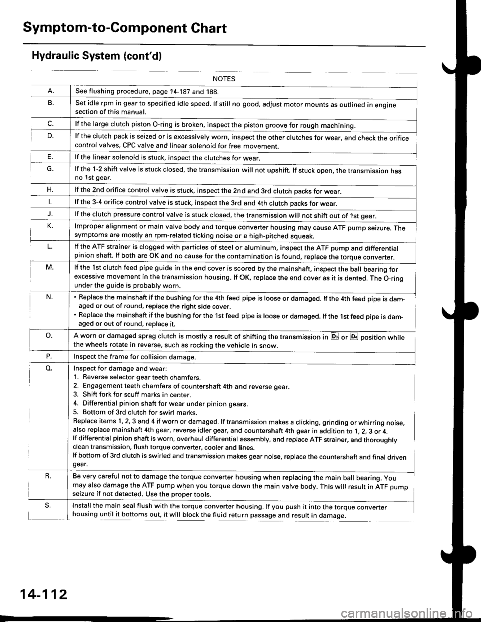
Symptom-to-Component Chart
Hydraulic System (cont'dl
G.
n,
set idle rpm in gear to specified idle speed. lf still no good, adjust motor mounts as outlined in enginesection of this manual.
lf the clutch pack is seized or is excessively worn. inspect the other clutches for wear, and check the orificecontrol valves, CPC valve and linear solenoid for free movement.
lf the linear solenoid is stuck, inspect the clutches for wear.
lmproper alignment or main valve body and torque converter housing may cause ATF pump seizure. Thesymptoms are mostly an rpm-related ticking noise or a high-pitched squeak.
lf the l st clutch feed pipe guide in the end cover is scored by the mainshaft, inspect the ball bearing forexcessive movement in the transmission housing. lf oK, replace the end cover as it is dented. The o-rinounder the guide is probably worn.
Replace the mainshaft if the bushing for the 4th feed pipe is loose or damaged. lf the 4th feed pipe is danFaged or out of round, replace the right side cover.
Replace the mainshaft if the bushing for the 1st feed pipe is loose or damaged. lf the 1st feed pipe is darn-aged or out of round, replace it.
A worn or damaged sprag clutch is mostly a result of shifting the transmission inthe wheels rotate in reverse, such as rocking the vehicle in snow.
or E position while
Inspect for damage and wear:
1. Reverse selector gear teeth chamfers.
2. Engagement teeth chamfers of countershaft 4th and reverse gear.
3. Shift fork for scuff marks in center.
4. Differential pinion shaft for wear u nder pin ion gears.
5. Bottom of 3rd clutch for swirl marks.
Replace items 1,2,3 and 4 if worn or damaged. lf transmission makes a clicking, grinding orwhirring noise,also replace mainshaft 4th gear, reverse idler gear. and countershaft 4th gear in addition to 1, 2, 3 or 4.lf differential pinion shaft is worn, overhaul differential assembly, and replace ATF strainer, and thoroughlyclean transmission, flush torque converter, cooler and lines.lf bottom of 3rd clutch is swirled and transmission makes gear noise, replace the countershaft and final drivengear.
Be very careful not to damage the torque converter housing when replacing the main ball bearing, you
may also damage the ATF pump when you torque down the main valve body. This will result in ATF pumpseizure if not detected. Use the oroper roors.
Install the main seal flush with the torque converter housing. lf you push it into the torque converterhousing until it bottoms out, it will block the fluid return passage and result in damage.
See flushing procedure, page 14-187 and 188.
lf the large clutch piston O-ring is broken, inspect the piston groove for rough machining.
lf the l-2 shift valve is stuck closed, the transmission will not upshift. lf stuck open, the transmission hasno 1st gear.
lf the znd orifice control valve is stuck. inspect the 2nd and 3rd clutch oacks for wear.
lf the 3-4 orifice control valve is stuck, inspect the 3rd and 4th clutch oacks for wear.
lf the clutch pressure control valve is stuck closed, the transmission will not shift out of 1st gear.
lf the ATF strainer is clogged with particles of steel or aluminum, inspect the ATF pump and differentialpinion shaft. lf both are OK and no cause for the contamination is found, replace the torque converter.
Inspect the frame for collision damage.
14-112
Page 1575 of 2189

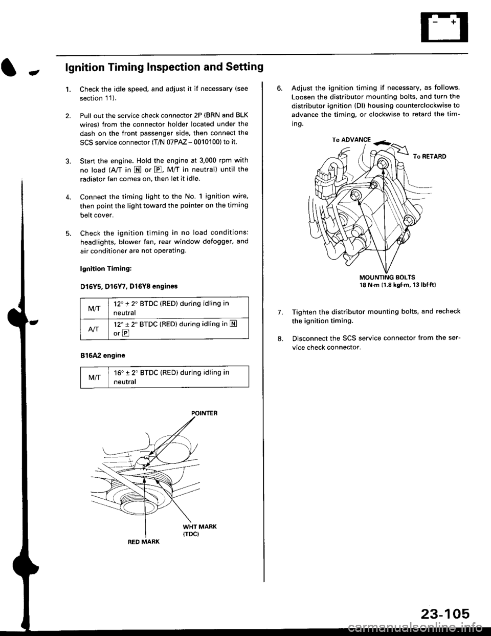
-lgnition Timing Inspection and Setting
1.Check the idle speed, and adjust it it necessary (see
section 'l '1 ).
Pull out the service check connector 2P (BRN and BLK
wires) from the connector holder located under the
dash on the front passenger side, then connect the
SCS service connector (T/N 07PAZ - 0010'100) to it.
Start the engine. Hold the engine at 3.000 rpm with
no load {A,/T in E or E. M/T in neutral) until the
radiator fan comes on, then let it idle.
Connect the timing light to the No. 1 ignition wire,
then point the light toward the pointer on the timing
belt cover.
Check the ignition timing in no load conditions:
headlights. blower fan, rear window defogger, and
air conditioner are not operating.
lgnhion Timing:
D15Y5. D16Y7, Dl6Yg engines
816A2 engine
MIT16" 12' BTDC (RED) during idling in
neutral
M/T12't 2" BTDC (RED) during idling in
neutral
l2'r 2" BTDC {RED) during idling in S
orE
POINTEB
RED MARK
23-105
ro ADVANCE -<;,
6. Adjust the ignition timing if necessary, as follows.
Loosen the distributor mounting bolts. and turn the
distributor ignition (Dl) housing counterclockwise to
advance the timing, or clockwise to retard the tim-
ing.
MOUNTING BOLTS18 N'm (1.8 kgfm, 13lblftl
Tighten the distributor mounting bolts, and recheck
the ignition timing.
Disconnect the SCS service connector from the ser-
vice check connector.
7.
Page 1588 of 2189

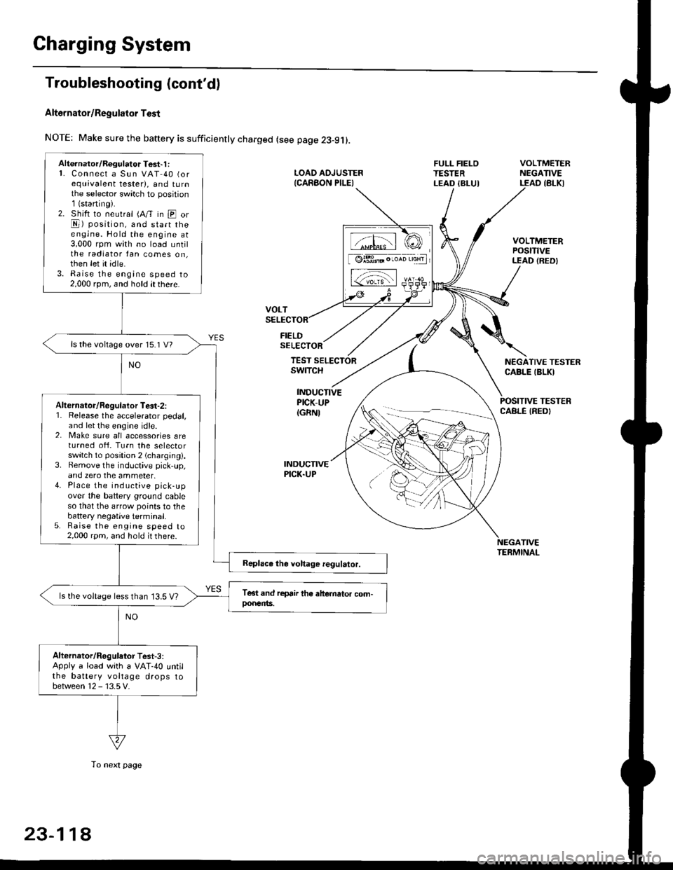
Charging System
Troubleshooting (cont'd)
Alt6rnator/Regulator Test
NOTE: Make sure the baftery is sufficiently charged (see page 23-9j).
FIELDSELECTOR
LOAD AOJUSTER{CARAON PILEI
FULL FIELOTESTERLEAD IBLUI
VOLTMETERNEGATIVELEAD IBLKI
VOLTMETERPOStTtVELEAD (REDI
NEGATIVE TESTERCABLE IBLKI
POSITIVE TESTERCABLE IREDI
TEST SELECTORswrTcH
INDUCTIVEPICK-UP
IGRNI
INDUCNVEPICK.UP
TIVETEBMINAL
Alte.nator/Regulator Test'1 :L Connect a Sun VAT 40 (orequivalent tester), and tu rnthe selector sw;tch to position1(staning).2. Shift to neutral (A/T in E orE) position, and start theengine. Hold the engine at3,000 rpm with no load untilthe radiator fan comes on,then let it idle.3. Raise the engine speed to2,000 rpm, and hold it there.
ls the voltage over 15.1 V?
Alternalor/Regulator Te3t-2:1. Release the accelerator pedal,and let the engine idle.2. Make sure all accessories areturned ofi. Turn the selectorswitch to position 2 (charging).3. Bemove the inductive pick-up,and zero the ammeter,4. Place the inductive pick-upover the battery ground cableso that the arrow points to thebattery negatlve terminal.5. Raise the engine speed to2,000 rpm, and hold it there.
ls the voltage less than 13.5 V?
Alternator/Regulator Test-3:Apply a load with a VAT-40 untilthe battery voltage drops tobetween 12 - 13.5 V.
tffil rCI
[ @lBt* . ,*n 'aHrl
L-;-;l rs-
23-11A
To next page
Page 1718 of 2189

Cruise Control
t
D=
t
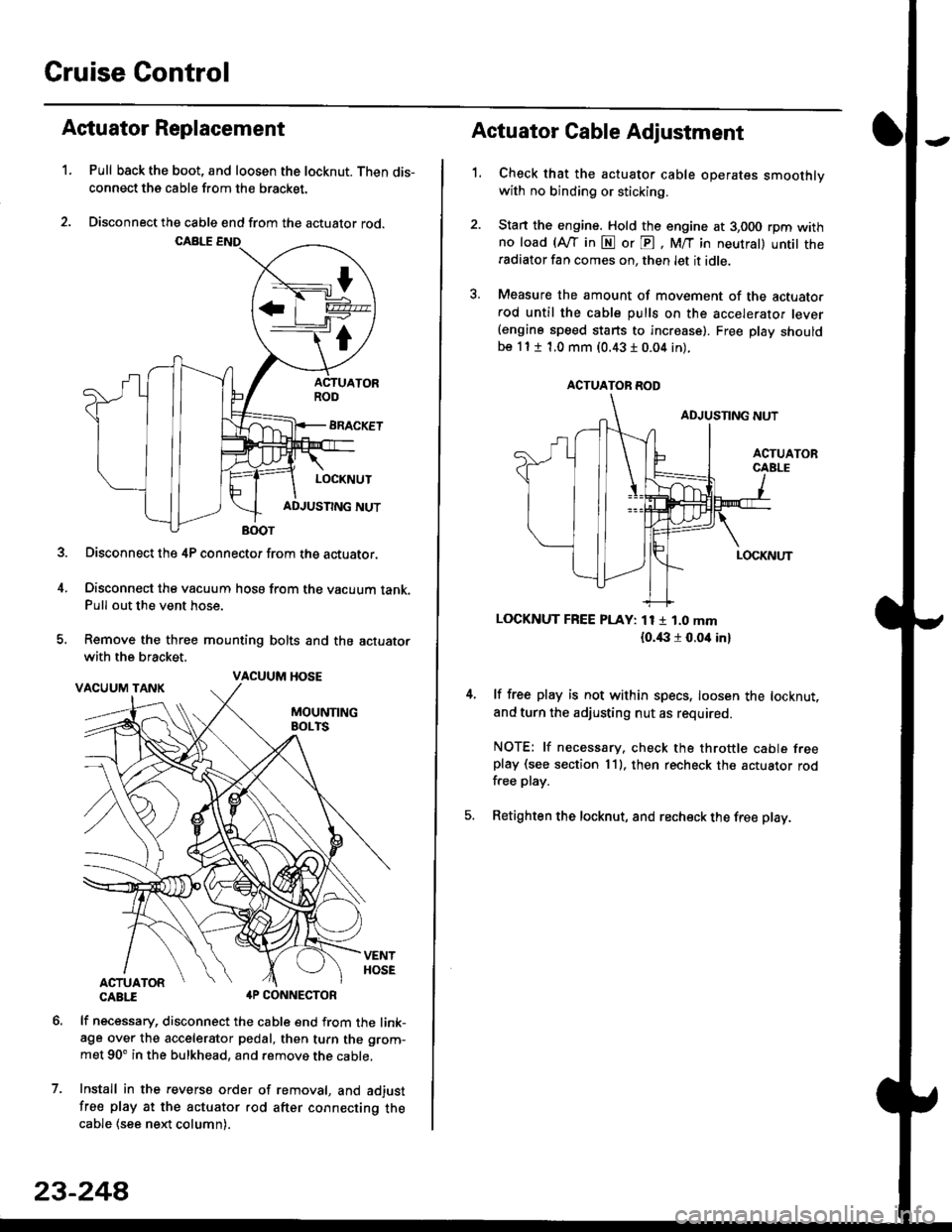
Astuator Replacement
1.Pull back the boot, and loosen the locknut. Then dis-
connect the cable from the bracket.
Disconnect the cable end from the actuator rod.
Disconnect the 4P connector from the actuator.
Disconnect the vacuum hosa from the vacuum tank.Pull out the vent hose.
Remove the three mounting bolts and the actuator
with the bracket.
CABTI aP CONNECTOR
lf necessary, disconnect the cable end from the link-age over the accelerator pedal, then turn the grom-
met 90' in the bulkhead, and remove the cable,
Install in the revers€ order of removal, and adjust
free play at the actuator rod after connecting thecable (see ne)d column).
7.
VACUUM HOSE
23-244
1.
Actuator Cable Adjustment
Check that the actuator cable operates smoothlywith no binding or sticking.
Stan the engine. Hold the engine at 3,000 rpm withno load (Afl'in N or E, M/T in neutral) untit theradiator fan comes on, then let it idle.
Measure the amount of movement of the actuato.rod until the cable pulls on the accelerator lever(engine speed starts to increase). Free Dlay shouldbe 11 t 1.0 mm (0.43 I 0.04 in).
LOCKNUT FREE PLAY: 11 1 1.0 mm
{o.i|:l r 0.oit in}
lf free play is not within specs, loosen the locknut,
and turn the adjusting nut as required.
NOTE: lf necessary. check the throttle cable freeplay (see section 11). then recheck the actuator rodfree play.
Retighten the locknut, and recheck the free play.
ACTUATOR ROD