Page 1956 of 2189
AiC Compressor Gontrols (cont'd)
- '99-'00 Models
From page 62.
v
I*"-ilii.,"r,
ihtli4
BLUAVHT
15
6LUAVHT
UNDER.HOODFUSE/RELAYBOX
Seg Pow6rDistrlbutiofl,pag€ 'l Gl1-c353PHO|O 8
l[,,*
';.!, "'""
,c,/cSwitch switchcommon itput
a,/cTHERMOSTATOlt below3"C (37"F).
THERMISTOR
(
B11A A8A B'IO |'r--:=---I A/C lgnition B€ttery II request input (backup) :
".j:[ru*,,ry "..;X
{;[
vtEW 57
HEATERCONTROLPANEL
l'lCswitch SwitchLgD IEDcodrol cormonGrouod
See AirD€livery,RgarWindowD€foggar
BIK
cl
ORN
c5
GBN
r,/cOt'llndicatof
HEATERPUSHswrTcHEs
t/cSwltch
S€e AirDelivefy,RearWindowDslogg6f
See GroundDist.ibdion,page 1,1-5.
Y
I(
=ffi;
(
.I UNDER.
I HOODi FUSE/I RELAYI Box
IJ
62-2
PHOfO 125
Page 1957 of 2189

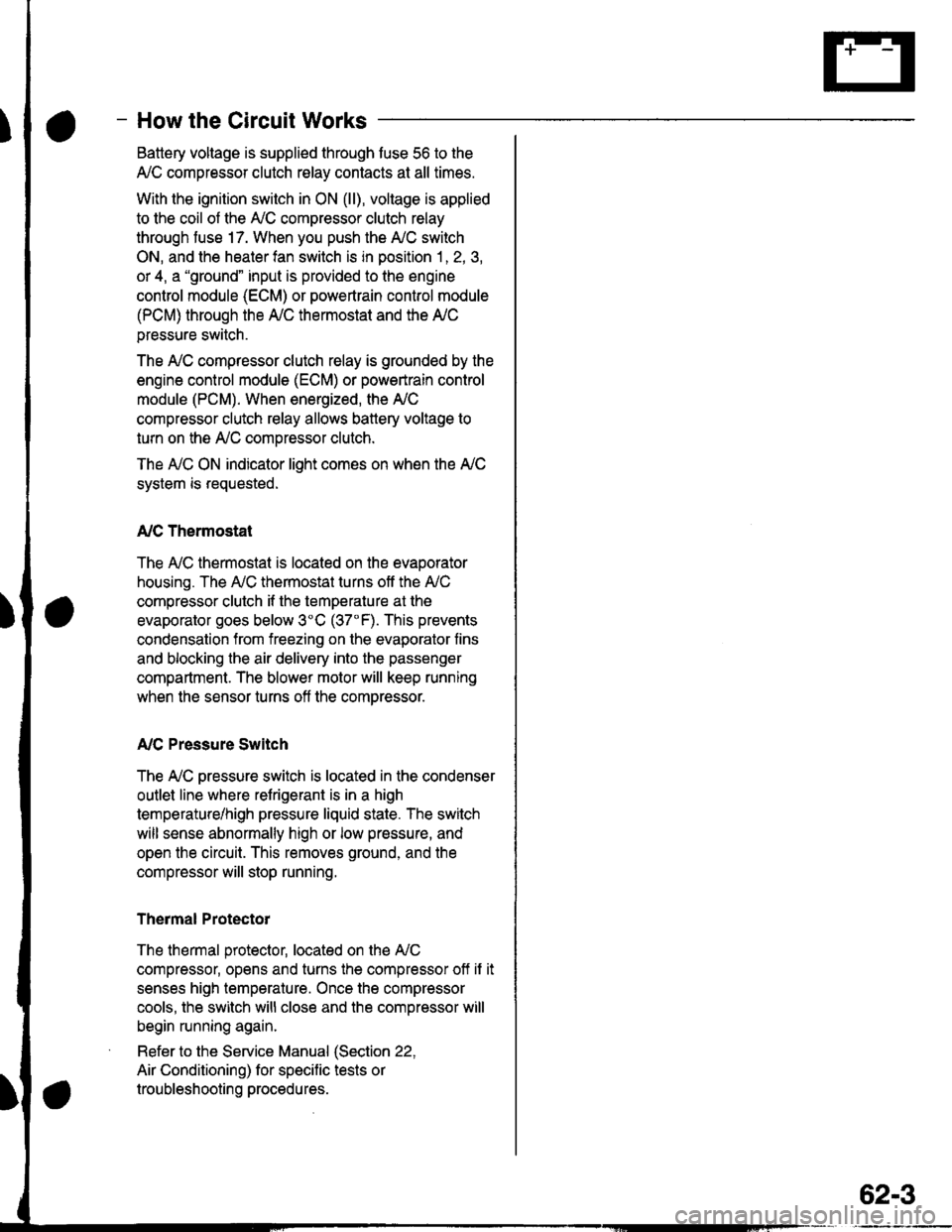
- How the Circuit Works
Battery voltage is supplied through tuse 56 to the
A,/C compressor clutch r€lay contacts at all times.
With the ignition switch in ON (ll), vollage is applied
to the coil of the A,/C compressor clutch relay
through fuse 17. When you push the A,/C switch
ON, and the heater fan switch is in position | , 2, 3,
or 4, a "ground" input is provided to the engine
control module (ECM) or powertrain control module
(PCM) through the l'lC thermostat and the l'lC
pressure switch.
The A,/C compressor clutch relay is grounded by the
engine control module (ECM) or powertrain control
module (PCM). When energized, the A'lC
compressor clutch relay allows battery voltage to
turn on the A,/C comDressor clutch.
The A,/C ON indicator light comes on when the A,/C
system is requested.
A,/C Thermostat
The A'lC thermostat is located on the evaoorator
housing. The A,/C thermostat turns off the A,/C
compressor clutch if the temperature at the
evaporator goes below 3'C (37'F). This prevents
condensation from freezing on the evaporator fins
and blocking the air delivery into the passenger
compartment. The blower motor will keep running
when the sensor turns off the comDressor.
A,/C Pressure Switch
The fuC oressure switch is located in the condenser
outlet line where refrigerant is in a high
temperature/high pressure liquid state. The switch
will sense abnormally high or low pressure, and
open the circuit. This removes ground, and the
compressor will stop running.
Thermal Protectot
The thermal protector, located on the A,/C
compressor, opens and turns the compressor off if it
senses high temperature. Once the compressor
cools, the switch will close and the compressor will
begin running again.
Refer to the Service Manual (Section 22,
Air Conditioning) for specific tests or
troubleshooting procedures.
62-3
Page 1960 of 2189
Fans (cont'd)
- '99-'00 Models
Switch"common
a,/cTHERMOSTATOff below3'C (37" F).
rla
iTm,il-- l5;i;T iln"lgg1
L_t]stE"_i*-o* !-J-___i
*-"'
"W"u'
".*L[F*f,l"' -*,".'"[ftT,;.'
I I .-.. Sse Power II ',-.', Sse Power I S€€ Pow€r
?+ 3s;iT:3:' ?'4 3ff:?f?l:
OEE I Dbfibution,
I pacp 10.9.
HEATERCONTROLPANEL
vlEw 76
A6
BLK
;+
::--
{***,Pase*11
ItI
rfa
r,/cswitchinputL-----
HEATERPUSHswtTcHEs
A/CSwlbh
See AirDslivery,n6arWindowDelogoor
S€e AltDeliv€ry,BaarWindowD€loggpr
See GroundDistribution,pag€ 1+5.
I
J;-a;
I I 'l rHERMrsroR I Ilt | 23 9--------------2, c723q/ f, ,2tr prtoroz!3a
tttlllnr ar-x,ver- | tn*t,".u IItI
orl "tol---riliii"--
inplt (backup)
i
I
Nclsvritcn Swikh ILED LEDcontrol cofrrnon Ground _ _.i
2Yl
^..._-_I t*-*"!
t2oV c723 I
- -_-\Tgr?;u L
---rF------
requ€si
63-2
a/cONlrdlcalqr
Page 1961 of 2189

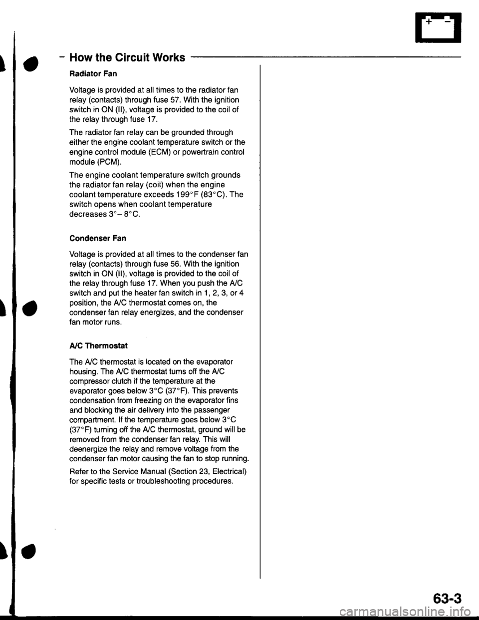
- How the Circuit Works
Radiator Fan
Voltage is provided at all times to the radiator fan
relay (contacts) through fuse 57. With the ignition
swilch in ON (ll), voltage is provided to the coil of
the relay through luse 17.
The radiator tan relay can be grounded through
either the engine coolant temperature switch or the
engine control module (ECM) or powertrain control
module (PCM).
The engine coolant temperature switch grounds
the radiator fan relay (coil) when the engine
coolant temperature exceeds 199'F (83'C). The
switch opens when coolanl temperature
decreases 3'- 8'C.
Condenser Fan
Voltage is provided at all times to the condenser fan
relay (contacts) through fuse 56. With the ignition
switch in ON (ll), voltage is provided to the coil of
the relay through fuse 17. When you push the A'lC
switch and put the heater fan switch in 1, 2,3, o( 4
position, the ly'C thermostat comes on, the
condenser fan relay energizes, and the condenser
fan motor runs.
A,/C Thermostat
The A,/C thermostat is located on the evaporator
housing. The A,/C thermostat tums off the A/C
compressor clutch if the temperature at the
evaporator goes below 3'C (37'F). This prevents
condensation from freezing on the evaporator fins
and blocking the air delivery into the passenger
compartment. lf the temperature goes below 3'C
(37"F) tuming off the Ay'C thermostat, ground will be
removed from the condenser fan relay. This will
deenergize the relay and remove voltage from the
condenser fan motor causing the fan to stop running.
Reter to the Service Manual (Section 23, Eleckical)
for specific tests or troubleshooting procedures.
63-3
Page 2120 of 2189

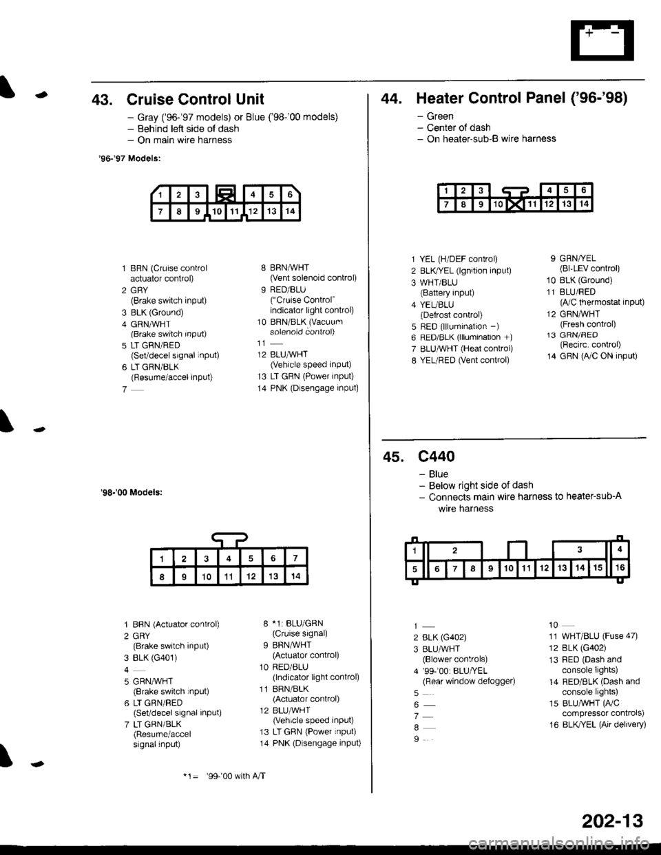
-43. Cruise Control Unit
- Gray ('96-'97 models) or Blue ('98-'00 models)- Behind lett side ol dash- On main wire harness
'96-'97 Models:
1 BRN (Cruise controlactuator control)
2 GBY(Brake switch input)
3 BLK (Ground)
4 GRN,ryVHT(Brake switch Input)
5 LT GRN/RED(Set/decel signal inPUt)
6 LT GRN/BLK(Resume/accel inPut)
7
'98-'00 Models:
'I BBN (Actuator control)
2 GRY(Brake switch input)
3 BLK (G401)
4
5 GRN,^/VHT(8rake switch rnput)
6 LT GRN/RED(Set/decel signal inPut)
7 LT GRN/BLK(Resume/accelsignalinput)
8 BRN,AiVHT(Vent solenoid control)
9 RED/BLU("Cruise Control"indicator light conkol)
10 BRN/BLK (Vacuum
solenoid controi)
12 BLUMHT(Vehicle speed input)
13 LT GRN (Power input)
14 PNK (Dlsengage input)
8 *1: BLU/GRN(Cruise signal)
9 BFN/WHT
{Actuator control)
1O RED/ALU(lndicator light conkol)
11 BRN/BLK(Actuator control)
12 BLU,ryVHT(Vehicle speed input)
13 LT GRN (Power input)
14 PNK (Dlsengage input)
\
17
II1011'121314
*1= 99-'00 w(h A/T
202-13
44. Heater Control Panel ('96-'98)
- Green- Center ol dash- On heater-sub-B wire harness
1 YEL (H/DEF control)
2 BLKTYEL (lgnition input)
3 WHT/BLU(Battery input)
4 YEUBLU(Defrost control)
5 RED (lllumination -)
6 RED/BLK (lllumination +)
7 ELUruVHT (Heat conkol)
8 YEL/RED (Vent control)
9 GRN/YEL(Bl'LEV control)
10 BLK (Ground)
11 BLU/FED(lVC thermostat input)
12 GRNMHT(Fresh control)13 GRN/FED(Recirc. control)
14 GRN (A/C ON input)
45. c440
- Blue- Below right side of dash- Connects main wire harness to heater-sub-A
wrre narness
2 BLK (G402)
3 BLU/WHT(Blower controls)
4 '99-'00: BLU/YEL(Rear window defoggeo
7
9
10
11 WHT/BLU (Fuse 47)
12 BLK (G402)
13 RED (Dash andconsole Iights)
14 RED/BLK (Dash andconsole lights)
15 BLUAVHT (FVC
compressor conkols)
16 BLK/YEL (Air delivery)
Page 2185 of 2189
Connectol
or
Terminal
Number of
Cavities/
Color
LocationConnects toNotes
Connector ldentification and Wire Harness Routing
HEATER SUB.HARNESS A
1"t-
Heater Sub-harness A: '96-'98 models
c440
c722
c723
c724
c725
c726
c727
1 6-BLU
7.GRN
2O.GRY
3-GRY
2.NAT
4-BRN
4.GRN
Under middle of dash
Behind middle ot dash
Behind front console
Behind glove box
Below right side of dash
Behind glove box
Behind glove box
Main wire harness
Mode control motor
Heater sub-harness B
A,/C thermostat
Blower motor
Blower motor resistor
Recirculation control motor
Heater Sub-harness Bt '96;98 models
c743
2O-GRY
6-BRN
14-GRN
Behind front console
Behind middle of dash
Behind middle of dash
Heater sub-harness A
Heater fan switch
Heater control panel
u.
HEATER SUB.HARNESS B
l\-
203-44
Page 2186 of 2189
) ._'
Connectol
o1
Terminal
Number ot
Cavltles/
Color
LocationConnects toNotes
Heater Sub-harness A: '99-'00 models
c440
c722
c723
c724
wlzc
c726
c727
c728
c729
c730
16.8LU
7-GRN
24-BLU
3-GRY
2-NAT
3-NAT
4.GRN
1-BRN
5-GRN
4-BRN
Under middle of dash
Behind middle of dash
Behind front console
Behind glove box
Below right side of dash
Behind glove box
Behind glove box
Behind front console
Behind glove box
Behind glove box
Main wire harness
Mode control motor
Heater sub-harness B
A'lC thermostat
Blower motor
Power transistor
Recirculation control motor
Heater sub-harness B
Air mix control motor
Blower motor high relay
Heater Sub-harness B: '99-'00 models
c723
c728
c742
c743
24.BLU
1-BRN
8-GRY
2O.BLK
Behind front console
Behind front console
Behind middle of dash
Behind middle of dash
Heater sub-harness A
Heater sub-harness A
Heater control panel conn€ctor A
Heater control oanel connector B
HEATER SUB.HARNESS A
HEATER SUB-HARNESS B
203-45