Page 915 of 2189

Symptom-to-Component Chart
Electrical System -'96 - 98 Models
*: The DTC in parentheses is the code @ indicator light indicates when the Data Link Connector is connected to the HondaPGM Tester.
DTC*O Indicator
LightMILDetection ltemPage
P1790
(3)BlinksONThrottle position sensor14-242
P179'l
(4)BlinksONVehicle speed sensor14-243
P1705
(5)BlinksONAy'T gear position switch (short to groundl't 4-244
P1706
(6)OFFONA/T gear position switch {open)14-246
P0725
(11)BlinksONlgnition coil14-248
P1793
112lBlinksONManifold absolute pressure sensor14-249
P 1870(30)BlinksONShift control linear solenoid14-250
P'1873
(311BlinksONPH-PL control linear solenoid14-25'l
P1879(32)BlinksONStart clutch control linear sotenoid14-252
P1882BlinksONInhibitor solenoid14-253
P1885
(34)BlinksONDrive pulley speed sensor1l-Zb4
P1886(35)BlinksONDriven pulley speed sensor14-255
P1888
(36)BlinksONSecondary gear shaft speed sensor14-256
T to55
(37)BlinksONECM or TCM14-257
P1890
l42lBlinksONShift control system14-259
P1891
(43)BlinksONStart clutch control svstem14-260
14-23a
Page 917 of 2189
Symptom-to-Com ponent Chart
Electrical System -'99 - 00 Models
r: The DTc in parentheses is the code E indicator light indicates when the Data Link connector is connected to the HondaPGM Tester.
DTCTE Indicatot
LighrMILDetostion ltemPage
P1705
(5)ElinksONA,/T gear position switch (short to grouno,14-265
P1706
(6)OFFONA"/T gear position switch (open)14-26€
P1870
(30)BlinksONShift control linear solenoid14-271
P1873
(31)BlinksONPH-PL control linear solenoid14-213
P1879
t32lBlinksONStan clutch control linear solenoid
Inhibitor solenoid
14-215
P1882(33)BlinksON't 4-277
P1885
(34)BlinksONDrive pulley speed sensol't 4-279
P1886
(35)BlinksONDriven pulley speed sensor14-281
P1888
(36)BlinksONSecondary gear shaft speed sensor
Shift control system
14-283
P1890
\421BlinksON14-245
P1891
(43)BlinksONStart clutch control system14-286
14-240
Page 919 of 2189

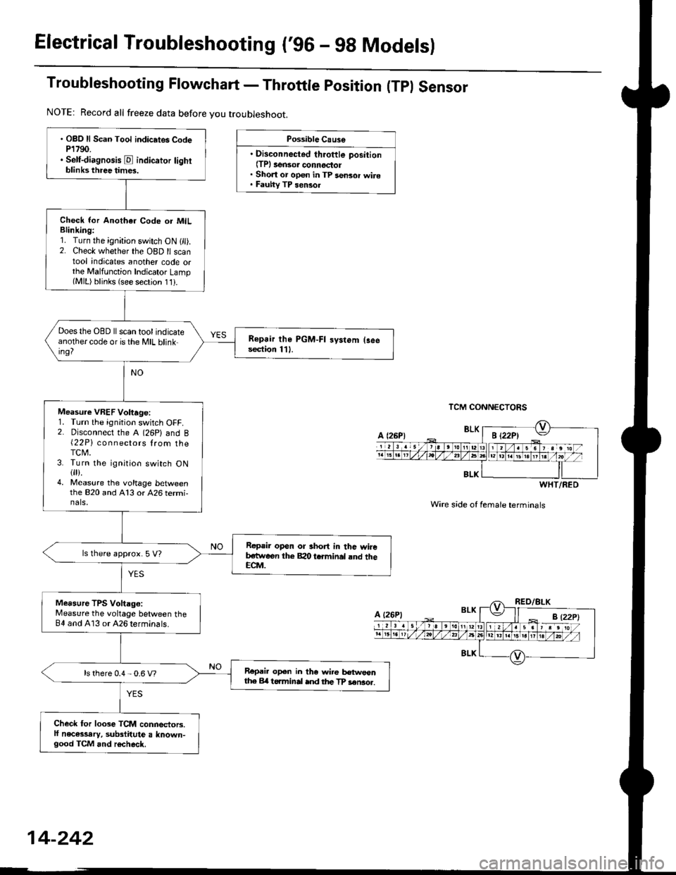
Electrical Troubleshooting ('96 - 98 Modelsl
Troubleshooting Flowchart - Throttle position (Tpl Sensor
Possible Cause
. Disconnected throftle position(TPl 3ensor connoctol. Short or open in TP sensor wire. Fauhy TP sensol
TCM CONNECTORS
Wire s;de of female terminals
. OBO ll Scan Tool indic.tes CodeP1790.. Self-diagnosis E indicator lightblinks three times.
Check lor Anothar Code or MILBlinking:1. Turn the ignition switch ON 1 ).2. Check whether the OBD ll scantool indicates another code orthe Malfunction Indicator Lamp(MlL) blinks (see secrion 11).
Does the OBD ll scan tool indicateanothercode oristhe MIL blink-ing?
Repair the PGM-FI systom (3eesection 111.
Measure VREF Voltage:1. Turn the ignition switch OFF.2. Disconnect the A (26P) and B{22P} connectors lrom theTCM.3. Turn the ignition switch ON{fl).4. Measure the voltage bet\iveenthe 820 and A13 or 426 termi-nals,
Repair open or short in thc wireb,stween the Bao tcrminal rnd theECM.
ls lhere approx. 5 V?
Measure TPS Voltago:Measure the voltage between theB4 and A13 or 426 terminals.
Repail open in the wire tr€tweonthe Erl t6.minal ind the TP sen3o..ls there 0.4 - 0.6 V?
Check for loose TCM connectors.lf necessary, substitute a known-good TCM and r6check.
NOTE: Record all freeze data before you troubleshoot.
BLK
WHT/RED
A {26P1
Page 920 of 2189

Troubleshooting Flowchart - Vehicle Speed Sensor (VSS)
NOTE: Record all freeze data before you troubleshoot'
Po$rible Ctuse
. Disconnected vehicle speed
sensor (VSS) connectol. Short or open in VSS wire' Faulty VSS
@. Make sure lifts, iacks, and sal€tY stands are placed properly lsoe section 1)'
. Set the parking brake securelv, and block the rear wheels'
. iacr upile rront or the vehicle, and support it with safety st'nds'
TCM CONNECTORS
Wire side of female terminals
. OBD ll Scan Tool indicates Code
P1791.. Setf-diagno3is E indicato. light
blinks tour times.
Refer to seclion 23 for vehicle
soeed sensor IVSSI test
Check the VSS Voltage:
1. Raise the vehicle2. Shift the transmission to lEposrtlon.3. Disconnect the A (26P) and B(22P) connectors from the
TCM.4. Turn the ignition switch ON {ll).
5. Rotate the front wheel and
check for the voltage between
the 85 and 413 or A26 termi-
nals. Block the other wheel so
at does not turn
Check for oP€n in the wire
between the 85 terminal and the
vehicle speed sensor {VSS}. lf
wire is OK, check the vSS (see
soction 23).
Does0Vandapprox 5 V or more
appear alternatelY?
Check for loos€ TCM connedors
lI nec€ssary, substitute a known'
good TCM and recheck.
14-243
Page 921 of 2189

Electrical Troubleshooting ('96 - 9g Models)
Troubleshooting Flowchart - A/T Gear position Switch (Short)
NOTE: Record all freeze data before you troubleshoot.
Posrible Cause
. Short in A/T go.r positionswitch wire. Faulty A/T g€ar polition switch
NOTE: Code P1705(5) is caused whenthe TCM receives two gear positionInputs at the same time.
TCM CONNECTOR A {26P}
Wire side of female terminals
To page 14-245
. OBD ll Scan Tool indicates CodeP1705.. Seif-diagnosis @ indicator lightblinksfive times.
Obsorve the A/T gear positionindicetor:1. Turn the ignition switch ON1[).2. Observe tho Ay'T gear positionindicator, and shift to eachposition separately.
Th6 lyrtcm i3 OK at thi. tima.Check the wi.s hamels for drm.ag9.
Do any jndicators stay on when thesh;ft lever is not in that position?
Measure ATP R Vohage:1. Shift to all positions other thanE.2. Measure the voltage betweenthe 411 and A13 or A26 termi-nats.
Check for sho.t in tho wireb€twoon the Al1 t rminaland th6A/l ge.r polhion switch or A/Tgear position indicstor. lf wilo isOK check for loos6 TCM conncc-tora. It nocassery, subrtitute aknown-good TCM and r€chsck.
ls there approx. 10 V?
Measure ATP NP Volt.ge:1. Shift to all positions otherthan @ or @.2. Measure the voltage betweenthe A10 and 413 or 426 termi-nals,Ch.ck tor 3hort in th€ wircb€twe€n thc Al0 termin.l andthe A/T 96r. porition indicrtor,or a short in the wilea b?twecntho A/T gerr porition indic.to.and the A/T geer positionswitch. It wires ar6 OK, chsck forloose TCM conn.clols. ll nccNe3-sa.y, substituto a known-goodTCM rnd locheck.
ls there approx. 10 V?
Measure ATP O Vohage:1. Shift to all positions otherthanE,2. Measure the voltage betweenthe Ag and A13 or 426 terminals.
Checl tor short in the wirelr€tweon tho A9 terminal and theA/T g6a. position 3witch. lf wireb OK. check tor loos€ TCM con-nectors. lf nocelsary, substhute aknown-good TCM and rechack.
ls there approx. '10 V?
14-244
b
Page 926 of 2189

Troubleshooting Flowchart - Manifold
NOTE: Record all freeze data before you troubleshoot
Absolute Pressure {MAPI Sensor
TCM CONNECTORS
Wire side of female terminals
PG.iblo Cau3€
. Dkconnoctod manilold .bsoluto
ore33urc IMAP) sensor connoc'
lor. Short or opcn in MAP s.nsor
MAP sen3or
. OBD ll Scan Tool indicates Code
P1793,. self-diagno3b E indicato. light
indicat€s Code 12.
Chock tor Another Cod€ or MIL
Blinking:1. Turn the ignition switch ON (ll).
2. Check whether the OBD ll scan
tool indicates another code or
the Mal{unction Indicator LamP(MlL) blinks (sse section 11).
Does the OBD llscan tool indicate
another code or isthe lVlL blink-
in9?
Measure VREF voltage:
1. Turn the ignition switch OFF.
2. Disconnect the A (26P) and B
(22P) connectors trom the
TCM.3. Turn the ignition switch ON (ll).
4, Measure the voltage between
the B2O and A13 or A26 termr
nals.
R€pair opon or 3hort in the wire
botwoan the 820 t€.minal and
the EcM.lsthere aPprox.5 V?
Msasure MAP IPB) volt.ge:
Measure the voltage betlveen the
82 and A13 or 426 terminals.
Repair opon ot shorl in the wiro
betwesn the 82 torminal end th€
MAP sensol.ls there approx. 3 V?
Check for loo3e TCM conn€stors.
lf nec*sarY, sub3titute a known'
good TCM and rechock.
WHT/RED
14-249
Page 942 of 2189

Electrical Troubleshooting ('99 - 00 Models)
Troubleshooting Flowchart - A/T Gear Position Switch (Short)
NOTE: Record all freeze data before you troubleshoot.
Po3sible Cause
. Short in A/T gear po3ition 3witch
. F.ulty A/T ge6r Position switch
NOTE: Code P1705(5) is caused when
the PCM received two gear Positioninputs at the same time.
PCM CONNECTORS
LGl (BRN/8LKI LG2 (BRN/8LKI
Wire side of female terminals
(cont'd)
14-265
B t25Pt llO(16P1
. oBD ll scln lool indicats code
P't705.. Self-diagnosb E indicator light
blinks fivetim€s.
Obseive tho A/T Gear Polition
lndicetor:1. Turn the ignition switch ON (ll).
2. Observe the A,/T gear positaon
indicator, and shift oach Posi-tion separately.
Tho ry3t6m is OK at this tims.
Check th€ wiro hsrno!! tor
damage.
Does any indicator stay on
when the shift lever is not an
that position?
M.Furo ATP R Vohtge:1. Shift to all positions other than
E.2. Measure the voltage between
the D6 and 820 or 822 termi'
nals,
Chock for lhort in tho wit€
betwe€n the D6 telminal and thg
A/T ge.r position 3witch or A/T
gear po3ition indicttoi, !nd
chcck for open in the witgs
botwo€n the 820 lnd 822 tetmi_n.ls and body g.ound (G1011. F
wiro3 ere OK, check tor loo3o ter'
minal fit in the PrCM connoctors.ll n6c€3sary, 3ubstitute a known-good PCM and rochock.
ls there approx. 10 V?
To page 14 266
Page 945 of 2189

Electrical Troubleshooting {'99 - 00 Models)
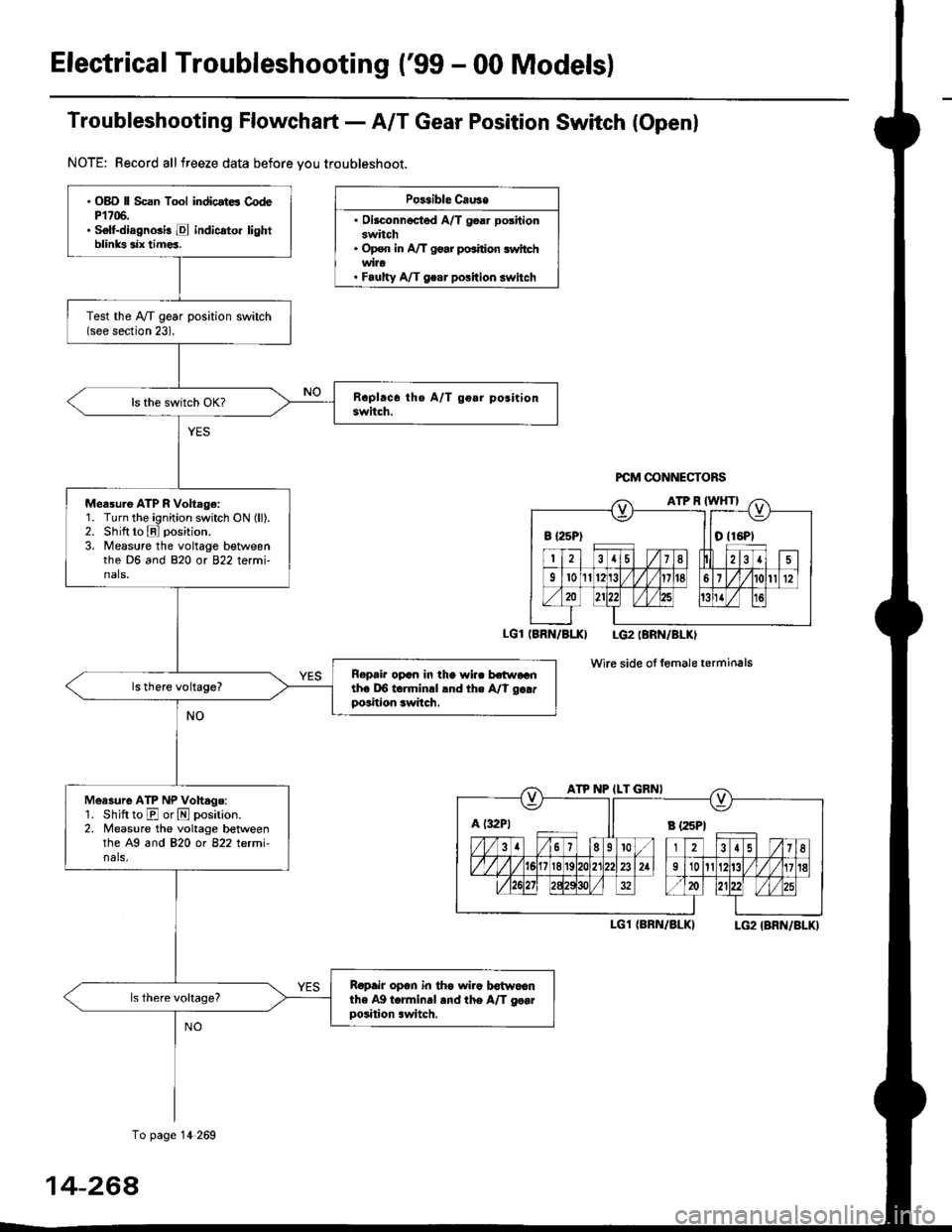
Troubfeshooting Flowchaft- AIT Gear Position Switch (Openl
NOTE: Record allfreeze data before vou troubleshoot.
Po$ible Cau3e
. Oilconnected A/T goar positionswitch. Op€n in A/T go.r po.ition switchwi?o. Faulty A/T gear polition switch
PCM @NNECTORS
(BRN/BI.XI LG2IBRN/BLKI
wire side of fomale terminals
I-G1 (BRN/BLKILG2 {BRN/BLK)
B {25P) I tO (16P1
ATP NP ILT GRNI
A t:r2Pt Il s tzspt
. OBD ll Scan Tool indicstE CodeP1706.. Selt-diagnGi! E indicato. lightblinks six tim€a.
Test the IVT gear position switch(see section 23).
Measu.e ATP R Voltage:1. Turn the ignition switch ON (ll).2. Shift to E position.
3. Measure the voltage betweenthe D6 and 820 or 822 termi-nals,
Ropair opcn in the wi.. hr.raGnth6 DO torminrl lnd the A/t g..rposition awitch.
Measure ATP NP Vohage:'1. Shift to E or N position.2. Measure the voltage betweenthe A9 and 820 ot 822 letmi-nals,
Ropair op6n in th€ wiro b€{woanthe Ag t.rminal and the A/T go..position .witch.
To page 14 269
14-264