1998 HONDA CIVIC connector plug
[x] Cancel search: connector plugPage 1468 of 2189
Condenser
Replacement
1.Recover the refrigerant with a recovery/recycling/
charging station lsee page 22-271.
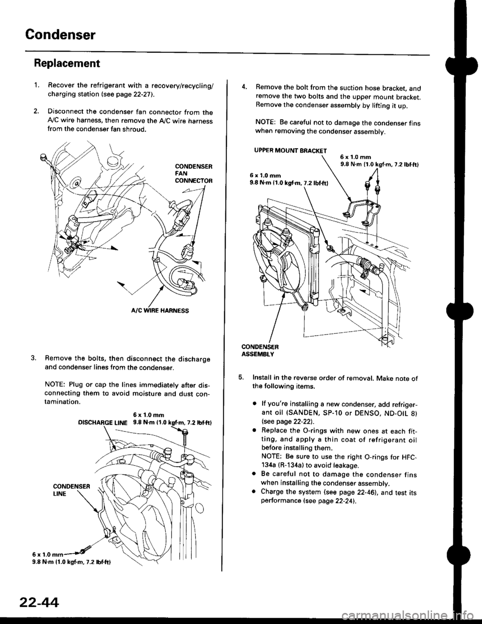
Disconnect the condenser fan connector from theAy'C wire harness, then remove the A,/C wire harnessfrom the condenser fan shroud.
Remove the bolts, then disconnect the dischargeand condenser lines from the condenser.
NOTE: Plug or cap the lines immediately after dis-connecting them to avoid moisture and dust con-tamination,
6r1.0
6x1.0mmolscHARGE L|NE 9.8 N.m 11.0
9.8 N.m 11.0 kgl.m, 7.2 lbf.ftl
22-44
4. Remove the bolt from the suction hose bracket, andremove the two bolts and the upper mount bracket.Remove the condenser assembly by lifting it up.
NOTE: Be careful not to damage the condenser finswhen removing the condenser assembly.
UPPER MOUNT BRACKET
5. Install in the reverse order of removal. Make note ofthe following items.
. lf you're installing a new condenser, add refriger-ant oil (SANDEN, SP-10 or DENSO, ND-O|L 8)
\see page 22-22l.-
. Replace the O-rings with new ones at each fit-ting, and apply a thin coat of refrigerant oilbefo.e installing them.
NOTE; Be sure to use the right O-rings for HFC,134a (R-134a) to avoid leakage.o Be careful not to damage the condenser finswhen installing the condenser assembly.. Charge the system (see page 22-46), and test itsperformance (see page 22-24i.
6x1.0mm9,8 N.m 11.0 kg{.m, 7.2lbtft}
6x1.0mm9.8 N.m 11.0 kst m, 7.2 lbf.ftl
Page 1471 of 2189

l'f .
Electrical
Special Toofs .,....................,23-2
Troubleshooting
Tips and Precautions ..............,.................... . 23-3
Five-step Troubleshooting .............. ......... . . 23-5
wire color codes ..........,23-5
Schematic Symbols ........,................... . . .. .... 23-6
Relay and Control Unit Locations
Engine Compartment ...,..................... ... .. . 23'7
Dashboard ......................23-8
Dashboard/Door ......... 23-12*Airbags ................. ....... Section 24
Air Conditioning ......... Section 21
Aftelnator ..........."""" """ 23-112
Anti-lock Brake System {ABS) Section 19*A/T Gear Position Indicator .....................,. .... ... 23-149
Automatic Transmission Svstem .... . ....... Section 14
Batterv ......... . . . ... ...... .......23-91
Blower controls .. . ... Section 2l
Charging System ....'...........23'112
Connector ldentilication and Wire Harness
Routing .................. ......23'13
Cruise Control ............,........23-240
Dash Lights Brightness Controller ............. ....... 23-180
Fan controfs "" 23'126
Fuel PumD ........ . ........ section 11
Fuses/Refay ...............,..,,.. 23'62
PGM-FI Control System ......................,....... Section 1 1
*Gauges
Circuit Diagram ....,.,.......23-131
Fuef Gauge ...........'.'.......23-142
Gauge/lndicator .. . .. 23-129
Ground Distribution .. . 23-75
Heatei controls .. . ..... Section 21*Horn................. ...............23-196
*tgnition Switch ....................23-89
lgnition System .......,.... 23-102
*lntegrated Control Unit ....................................... 23-156
fnterlock System ,........ . . , ,23-144
Lighting System . . . .. ......... 23-161
Lights, Exterior
Back-up Lights ..'............23'171
Brake Lights .................. 23'174
Daytime Bunning Lights (Canadal ............... 23'166
Front Parking Lights ......,................ .'. .......... 23-167
Front Turn Signal Lights .......... . . ............ ..,.23-167
Headtights ....".'....-... ..... 23'167
High Mount Brake Light ...................... ... .23'179
License Plate Lights ...... 23'176
Taitfights ................ .......23'171
lnterior Lights ..-.......,, . 23-142
Moonroof ..,.................,........ 23-235
Power Distribution ....... . . .23-61
Power Door Locks .......,,,. .23'251
Power Mirrors ,..............,.,...23'206
Power Relays ....... . ...... . . .. 23-86
Power Windows ............,,....23-220
Rear Window Defogger .......................... . . ... . . 23-2OO
Spark Plugs . ..... . ........ .....23-111
Slarting System ................23-93*stereo Sound Svstem ,................. ..... ... . ... ,.,.,,23'147'Supplemental Restraint System (SRS) ... . Section 24
Turn Signal/Hazard Flasher System .......'.'....-... 23-173
*Undel-dash Fuse/Relay Box ............,.................. 23-85
vehicfe soeed sensor (VSSI """" ""' 23-140+Wipers/Washers .........,.,.,...23-214
NOTE: Unless otherwise specified, references to auto-
matic transmission (Mf) in this section include the CVT.
Page 1565 of 2189
-Starter Test
NOTE; The air temoerature must be between 59 and
100'F (15 and 38"C) before testing.
Recommended Procedure:
. Use a staner system tester.
. Connect and operate the equipment in accordance
with the manufacturer's instructions.
. Test and troubleshoot as described,
Alternate Procedurg:
. Use the following equipment:- Ammeter, 0 - 400 A
- Voltmeter, 0 - 20 V (accurate within 0.1 volt)
- Tachometer, 0 - 1,200 rpm
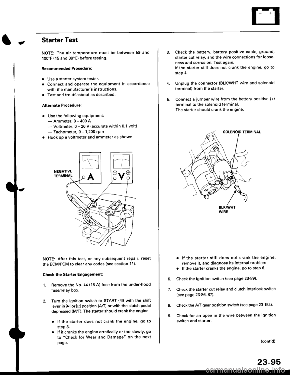
. Hook up a voltmeter and ammeter as shown.
NEGATIVETERMINAL
NOTE: After this test, or any subsequent repair. reset
the ECM/PCM to clear any codes (see section l1)
Check the Start€r Engagemont:
1. Remove the No. 44 (15 A) fuse from the under-hood
fuse/relay box,
2. Turn the ignition switch to START (llll with the shift
lever in E or E position (rVT) or with the clutch pedal
depressed {M/T). The starter should crank the engine.
. lf the starter does not crank the engine, go to
step 3.
. lf itcranksthe engineerraticallyortooslowly, go
to "Check for Wear and Damage" on the next
page.
Check the battery. battery positive cable, ground,
starter cut relay, and the wire connections for loose-
ness and corrosion, Test again.
lf the starter still does not crank the engine, go to
step 4,
Unplug the connector (BLK,/WHT wire and solenoid
terminal) from the starter,
Connect a jumper wire from the battery positive (+)
terminal to the solenoid terminal.
The starter should crank the engine.
. lf the starter still does not crank the engine,
remove it, and diagnose its internal problem
. lf the startercranksthe engine, goto step 6.
Check the ignition switch (see page 23-891.
Check the starter cut relay and clutch interlock switch
(see page 23-86,87).
Check the A/f gear position switch (see page 23-154).
Check for an open in the wire between the ignition
switch and starter.
7.
(cont'd)
23-95
9.
Page 1572 of 2189
lgnition System
Component Location Index
IGNITION TIMING CONTROL SYSTEM
. Troubleshooting, section 11
. ldle speed Inspection/Adjustment. section 11
. Inspection and Setting, page 23-105
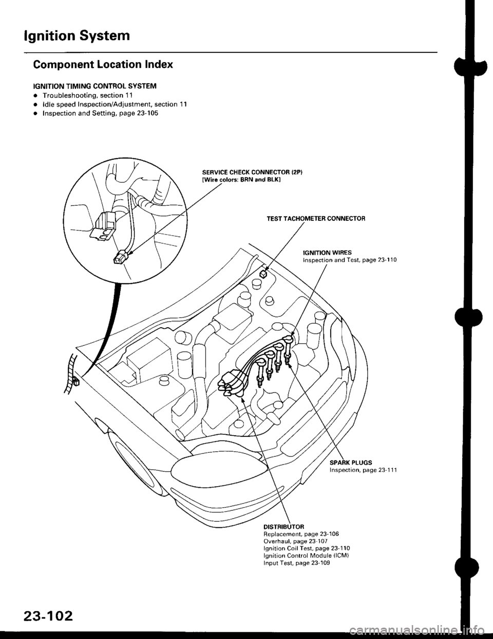
SERVICE CHECK CONNECTOR {2P}Iwiie colors: 8RN and BLKI
TEST TACI{OMETER CONNECTOB
IGNITION WIRESlnspection and Test, page 23-110
PLUGSInspection, page 23 1 11
Replacement, page 23'106Overhaul, page 23-107lgnition Coil Test, page 23'110lgnition Control Module llCM)Input Test, page 23-109
23-102
Page 1717 of 2189
)Actuator Test
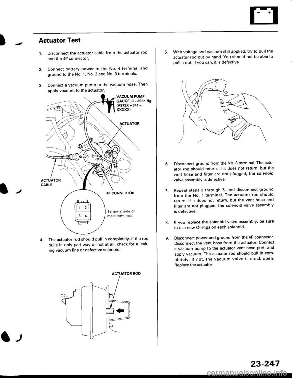
't.Disconnect the actuator cable from the actuator rod
and the 4P connector.
Connect battery power to the No 4 terminal and
ground to the No. 1, No. 2 and No. 3 terminals.
Connect a vacuum pump to the vacuum hose Then
apply vacuum to the actuator.
2.
VACUUM PUMPGAUGE,0 - 30 in.Hg.
{A973X - 041 -
xxxxxl
ACTUATOR
,lP CONNEcToR
Terminalside o{male termrnals
4. The actuator rod should pull in completely. lf the rod
pulls in only pan-way or not at all' check for a leak-
ing vacuum line or defective solenoid.
ACTUATOF ROD
l-t
23-247
5. With voltage and vacuum still applied, try to pull the
actuator rod out by hand. You should not be able to
oull it out. ll you can, it is defective
1.
Disconnect ground from the No.3 terminal. The actu-
ator rod should return lf it does not return, but the
vent hose and filter are not plugged, the solenoid
valve assembly is defective.
Repeat steps 2 through 5, and disconnect ground
from the No. 1 terminal. The actuator rod should
return. lI it does not return, but the vent hose and
filter are not plugged. the solenoid valve assembly
is defective.
It you replace the solenoid valve assembly, be sure
to use new O-rings on each solenoid.
Disconnect power and ground from the 4P connector.
Disconnect the vent hose from the actuator. Connect
a vacuum pump to the actuator vent hose port, and
apply vacuum. The actuator rod should pull in com-
pletely. lf not, the vacuum valve is stuck open.
Replace the actuator'
8.
Page 1871 of 2189
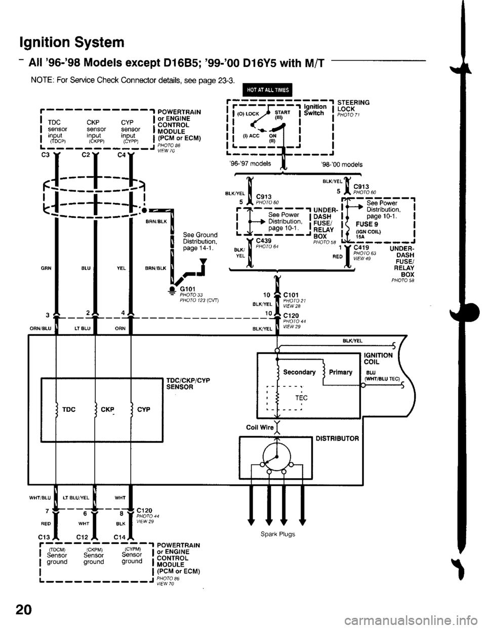
lgnition System
- All '96-'98 Models except Dl685; '99-'00 Dl6Y5 with M/T
NOTE: For Service Check Connector details, see page 23-3.
@
CKP CYPsensor sensorinput input(CKPP) (CYPP)
X,*.,
rDcsensorInpur(IDCP)
POWERTRAINor ENGINECONTROLMODULE(PCM or ECM)
POWERTRAINor ENGINECONTROLMODULE(PCM or ECM)
xr*"
BLKI/EL
I
I
BLK/YEL
I See Power
H Distribution,
J__99'�"'_
I
I
I
I
I
I
UNOER-OASHFUSE/RELAYBOX
"a*,telfi
u I """%t'3.
,rrrr.iFiFx".-,''ril'fi :T-DASH ll pagelo-1.FUSE/ I( FUSE 9
F.itl, Lq::---
".:lo63
10
BLK,YEL
10
c101
vlEW28
c'120
vlEW29
BLK
c14
c120
vlEW29
rIDcM) IGKPM) (CYPM)Sensor Sensor Sensolground ground ground
L-- - - -- -----J PHora 36
L-----------J
:L_1__I,
! iii:?ifq"l
I
**:'
*-"*,t";'
= PHO|O 33PHOTO 123ICW)
Secondary
ti <..-/4 i t
iLi:"_gl_i iL-----1!-----r
96- 97 models I 98- 00 modets
20
Spark Plugs
Page 1873 of 2189
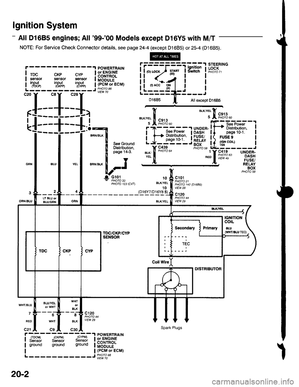
lgnition System
- All Dl685 engines; All '99-'00 Models except Dl6Y5 with M/T
NOTE: For Service Check Connector details, see page 24-4 (except D1685) or 25-4 (D1685).
STEERINGLOCKPOWERTRAIN
lm- sii.- s*- iffffiEgr
I '8f", '3#n '3#n | (Pcn' or EcM)
L------ -----J Wro 86
',L_I__J,
!l---+--l !
'i---
j----i'
fl '","?siii,xl
I I I
i*n"'."
-"1 "-l '-l *"-^lr";J
I I I ='i.{i31i",,-
All except D1685D1685
gLK.Yer t
u l9f#'
fi
"*1,[
F,*';.,
!'T-f*-'i"i! {F+ Distdbution,
LJ_gg'n'_
i.x,r
9'x*"
-.t
iF--Hs-,mT-l
ll pase lGi. I
l( FUsEe I
!Lig::___J
.I UNDER-I DASH
a FUSE/
! RELAY- BOX
1 Y C419 UNDER-^,ol',lill,l?"u' rlir?IA) RELAYBOX
.t0
BLKI/EL
10(D16Y7/D16Y8 s)
c101
PHO|O 142 lA1685)vlEw 2a
c120
vtEw 29OFN/ALULT BLU orALU/GRN
BLU,^VEL
c120
vtEw 29
ELKWHT/BLU
7
FED
c21c9
ALK
c30
;;--;;---o;;;lSensor Sonsor Sensor I
POWERTRAINor ENGINECONTROLMODULE(PCM or ECM)
ground ground gtound
L ------ -----J PHoro 36
Sec!l|dary
Sparh Plugs
20-2