Page 1591 of 2189
JRectifier Removal
1. Remove the four through bolts.
Heat the rear bearing seat with a 1,000 W hair drier
tor about five minutes (120 - 140'F, 50 - 60"C).
3. Separate the rear housing from the drive-end hous-
ing by inserting a flst tip screwdriver into the open-
ings and prying them a part. Be careful not to dam-
age the stator with the tip of the screwdraver.
Seoarate the rear housing and drive-end housing
with the stator attached to the rear housing.
DEIVE-END HOUSING
STATOR
{cont'd)
23-121
REAR HOUSING
Page 1630 of 2189

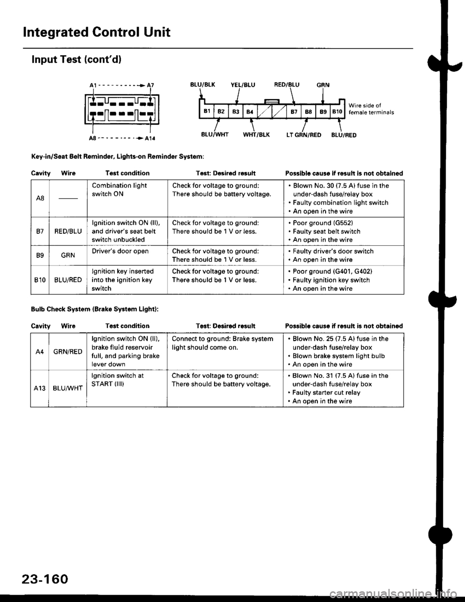
Integrated Gontrol Unit
Input Test (cont'dl
A8--------.--all
Key-in/Seat Belt R€mind€r, Lights-on Reminder Systom:
Cavity WireTest condhion
Bulb Check System (Brako System Light):
Cavity WireTest condilion
Tost: D€sirod r€guh
T6st: Dosirad result
Possible cause if result is not obtained
Possibls cause if rasuft b not obtainod
A8
Combination light
switch ON
Check for voltage to ground;
There should be battery voltage.
Blown No.30 (7.5 A)fuse in the
under-dash fuse/relay box
Faulty combination light switch
An open in the wire
B7RED/BLU
lgnition switch ON (ll),
and driver's seat belt
switch unbuckled
Check for voltage to ground:
There should be 1 V or less.
Poor ground (G552)
Faulty seat belt switch
An open in the wire
B9GRNDriver's door openCheck for voltage to ground:
There should be 1 V or less.
. Faulty driver's door switch. An open in the wire
Bl0BLU/RED
lgnition key inserted
into the ignition key
switch
Check for voltage to ground:
There should be 1 V or less.
Poor ground (G401. G402)
Faulty ignition key switch
An open in the wire
A4GRN/RED
lgnition switch ON {ll),
brake fluid reservoir
full, and parking brake
tever oown
Connect to ground: Brake system
light should come on.
Blown No.25 (7.5 Alfuse in the
under-dash fuse/relay box
Blown brake system light bulb
An open in the wire
A13BLUA/1r'HT
lgnition switch at
START (III)Check for voltage to ground:
There should be battery voltage.
Blown No.31 (7.5 A) fuse in the
under-dash fuse/relay box
Faulty starter cut relay
An open in the wire
23-160
Page 1638 of 2189

Headlights
Adjustment
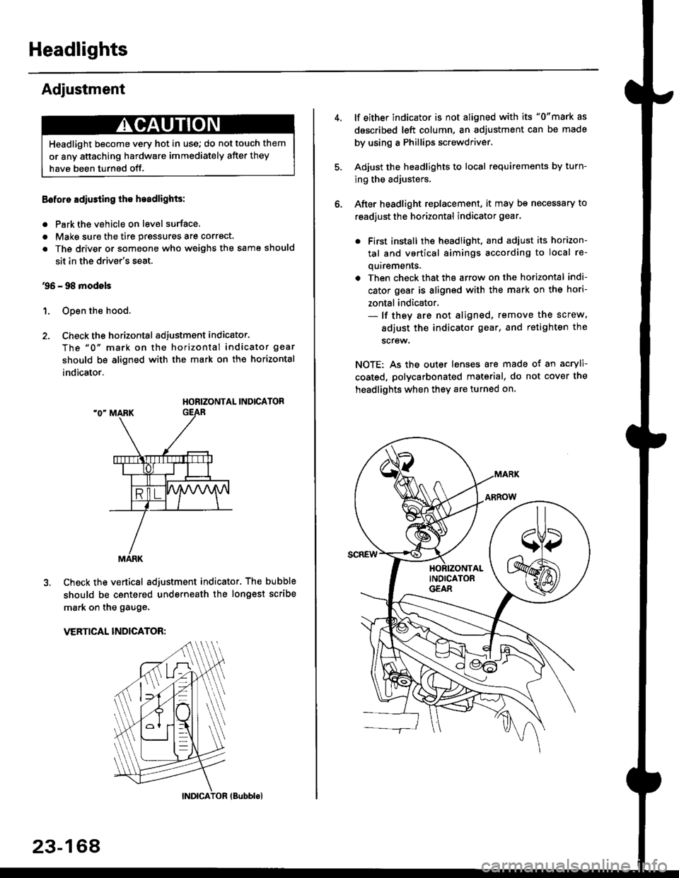
Eoforo adiu3ting th€ h.adlights:
. Park the vehicle on level surface.
. Make sure the tire prgssures are correct.
a The driver or someone who weighs the same should
sit in the driver's seat.
96 - 98 modols
1. Open the hood.
2. Check the horizontal adjustment indicator.
The "0" mark on the horizontal indicator gear
should be aligned with the mark on the horizontal
indicator.
HORIZONTAL INDICATOR
Check the vertical adjustment indicator. The bubble
should be centered underneath the longest scribe
mark on the gauge.
VERTICAL INDICATOR:
Headlight become very hot in use; do not touch them
or any attaching hardware immediately after they
have been turnsd off.
MARK
23-164
(Bubblol
lf either indicator is not aligned with its "0"mark as
described left column, an adjustment can be made
by using a Phillips screwdriver.
Adjust the headlights to local requirements by turn-
ing the adjusters.
After headlight replacement, it may bs necessary to
readjust the horizontal indicator gear.
. First install the headlioht, and adjust its horizon-
tal and vertical aimings according to local re-
quirements.
. Then check that the arrow on the horizontal indi-
cator gear is aligned with the mark on the hori-
zontal indicator.- lf they are not aligned, remove the screw,
adiust the indicator gear, and retighten the
screw.
NOTE: As the outer lenses are made ot an acryli-
coated, polycarbonated material, do not cover the
headlights when they are turned on.
Page 1743 of 2189

Description
)
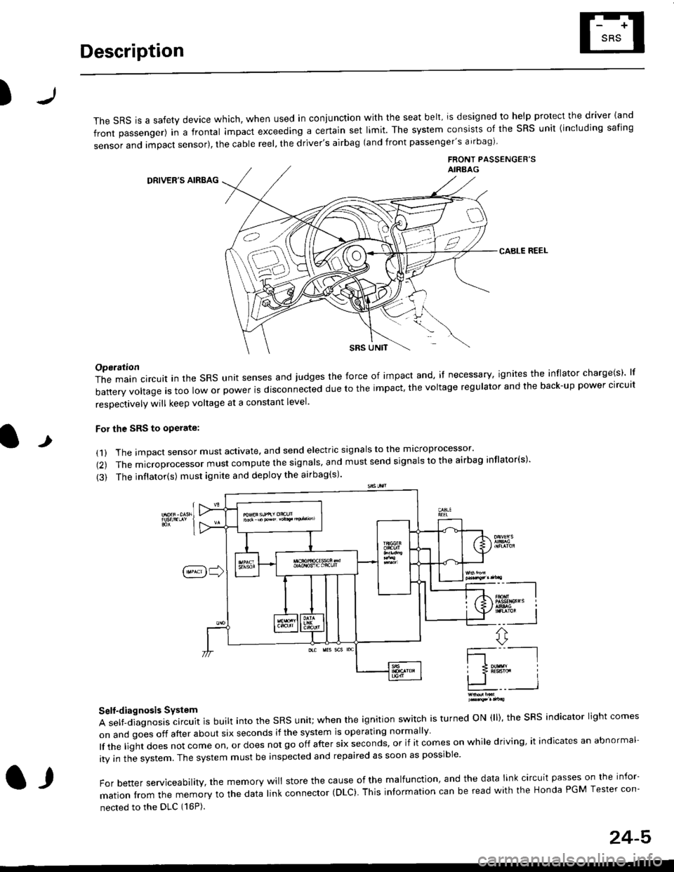
The sRS is a safety device which, when used in coniunction with the seat belt, is designed to help protect the driver land
front passenger) in a frontal impact exceeding a certain set limit. The system consists of the sRS unit {including safing
sensor and impact sensor), the cable reel, the driver's airbag (and front passenger's airbag)
FRONT PASSENGEB'SAIRAAG
DRIVER'S AIRBAG
CABLE REEL
SRS UNtT
t
Operation
The main circuit in the SRS unit senses and judges the force of impact and, if necessary, ignites the inflator charge(s) lf
battery voltage is too low or power is disconnected due to the impact, the voltage regulator and the back-up power clrcult
resoectivelv will keep voltage at a constant level.
For the SRS to operate:
(1) The impact sensor must activate. and send electric signals to the mlcroprocessor'
(2) The microprocessor must compute the signals' and must send signals to the airbag inflator(s)'
{3) The inflator(s) must ignite and deploy the airbag(s)'
_"-_-l
Ir3B!#h i
!.. I
ffi,*
Self-diagnosis System
A self-diagnosis circuit is built into the SRS unit; when the ignition switch is turned ON (ll), the SRS indicator light comes
on and goes off after about six seconds if the system is operating normally
lf the liglt does not come on, or does not go off after six seconds, or if it comes on while driving, it indicates an abnormal-
ity in the system. The system must be inspected and repaired as soon as possible
For better serviceability, the memory will store the cause of the malfunctlon, and the data link circuit passes on the infor-
mation from the memory to the data link connector (DLC). This intormation can be read with the Honda PGM Tesler con-
nected to the DLC (16P).
l,
24-5
Page 1866 of 2189
_t
89c559
Wrth. - - MilrorFUEL , DetoggerTANKUNIT ' RIGHTpaoes 74 ; POWERanj sr -r , MIBRORPHofo 103 | Page 141-2
i-l : i-l
I ltl I
,,:l'it{;
FUELTANKFUEL INTERNALPUMP SOLENOIDPaqe 23-1 VALVEor1q: Page 25-1PHOTO 103 PHOTO 145
r-.| r-'r
tttl
tttlL-J L-J'l
:l'a,t,
- G501 and G502
'9&'98
m@els
NOTE: Wires shown without color codes are black.
DRIVER'SSEATBELTSWITCHPage 73
tl
tl
STEREORADIO AUDIOTUNER UNITPage 150-1 Page 150-1PHOTO 73 PHOTO 137vtEw 6a vlEw 74
F-.|F-.1
ttll
trtlL-J L-J-.I 'I
93'c557
vtEW 62
'99'00
modelexceprDl685
14
G501
14-9
!-6ssz
Page 1971 of 2189
How the Circuit Works
Seat Belt Warning
With the ignition switch in ON (ll) or START (lll),
battery voltage is applied to the seat belt reminder
light. When the seat belt is not buckled, the seat
belt reminder/key-on beeper circuit in the
integrated control unit senses ground through the
closed seat belt switch. The seat belt reminder light
comes on and stays on, and the beeper beeps for
6 seconds. The reminder light and beeper will stop
when the seat belt is buckled or the timer circuit
deactivates them.
lgnition Key Warning
Battery voltage is supplied at all times to the seat
belt reminder/key-on beeper circuit in the
integrated control unit. When you turn on the
ignition key switch the integrated control unit
senses ground. lf you open the driver's door, the
door switch closes, causing the beeper to sound
until the door is closed.
Refer to the Service Manual (Section 23, Electrical)
for specitic tests or troubleshootrng procedures.
73-1
Page 2095 of 2189
Cornponent Location
85. Behind Right Kick Panel\
\
88. Driver's Door
CONNECTOR B ii
86. Behind Right Kick Panel89. Top Front of Driver's Door (Frt. Pass. Similar)
87. Underside of Driver's Seat90. Front of Driver's Door (Frt. Pass. Similar)
201-14
\
Page 2097 of 2189
Component Location
97. Left Rear Door Striker Area (Right Similar)\
\
100. Below Left Side of Rear Seat (Right Similar)
98. Driver's Door Sill101. Left of Rear Seat (Sedan Shown, Others Similar)
99. Left Center Pillar (Right Similar)102. Genter of Rear Shelf (Coupe/Sedan)
201 -16
\