1998 HONDA CIVIC Cvt transmission
[x] Cancel search: Cvt transmissionPage 1015 of 2189

1.
7.
lnstall the ATF feed pipe in the transmission hous-
ing, and install the three ATF feed pipes with new
O-rings in the transmission housing,
Install the two dowel pins and new transmission hous-
ing gasket on the transmission housing.
Push the control shaft assembly toward the outside
of the transmission housing, then install the inter-
mediate housing assembly (four bolts).
lnstall the manual valve body separator plate and
the two dowel pins on the intermediate housing,
then install the rnanual valve body with the detent
spring (five bolts).
Put the control shaft assembly back, then install the
roller in the intermediate housing.
lnstall the reverse brake piston in the intermediate
housing.
Install the spring retainer/return spring assembly on
the reverse brake Piston.
NOTE: Installthe return springs on the spring guides
of the reverse brake piston securely
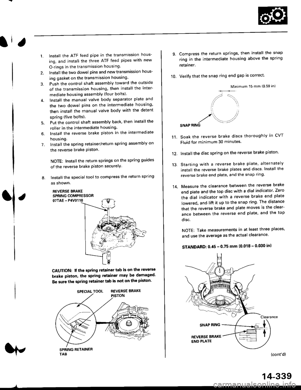
tnstall the special tool to compress the return spring
as shown.
REVERSE BRAKESPRING COMPRESSOR07TAE - P4V0110
6.
L
1
CAUTION: lf the spring retainer tab is on the reverse
brakc piston, the spring rstainer may be damaged'
Be sure the spring retainer tab is not on the piston'
rp
SPECIALTOOL REVERSEBRAKE
-^
14-339
10.
9.
14.
Compress the return springs, then install the snap
ring in the intermediate housing above the spring
retainer.
Verify that the snap ring end gap is correct'
Mini
/,,- '-t,,,,.
// \i/ ',r
'1 ,
.r' //'/. .-J?RINGSNAP
mum 15 mm 10.59 in)
Soak the reverse brake discs thoroughly in CVT
Fluid for minimum 30 minutes.
Installthe disc spring on the reverse brake piston'
Starting with a reverse brake plate, alternately
install the reverse brake plates and discs lnstall the
reverse brake end plate, and the snap ring'
Measure the clearance between the reverse brake
end plate and the top disc with a dial indicator' Zero
the dial indicator with a reverse brake end plate
lowered, and lift it up to the snap ring The distance
that the reverse brake and plate moves is the clear-
ance between the reverse end plate, and the top
disc.
NOTE: Take measurements in at least three places'
and use the average as the actual clearance'
STANDARD: 0.45 - 0.75 mm (0.018 - 0'030 in)
{cont'd)
11.
12.
13.
Page 1027 of 2189

22. Install the shift cable end on the control lever, and
install the shift cable on the shift cable bracket'
CAUTION: Take care not to bend the shift cable'
23. lnstall the clip in the direction shown.
LOCKNUT
SHIFI CABLE 29 N m {3.0 kg{ m, 22lblftl
SHIFT CABLEERACKET
WASHERIPLASTIC)
CONTROL LEVER
24, Connect the solenoid harness connector. the drive
pulley speed sensor connector. and the ground
cable terminals.
6x1.0mm12 N.m {1.2 kgf.m.8,7 rbtft)
GROUND CABLETERMINAL 6x1.0mm
GROUNDTERMINAL
12 N.m {1.2 kgf'm,8.7lbtfrl
DRIVE PULLEYSPEED SENSORCONNECTOR
SOLENOID HARNESS
CONNECTOR
25. Connect the starter motor cable on the starter motor.
and install the cable holder.
NOTE: When installing the staner motor cable. make
sure that the crimped side of the ring terminal is
facing out (see section 23).
STARTEB
BMOUNTING NUT
9 N.m (0.9 kgf m,7 lbf ft)
26. Install all removed connectors and clamps'
27. Install the distributor.
28. Install the intake air duct and air cleaner housing
29.
assemDly.
Refill the transmission with the recommended
Genuine Honda CVT Fluid (see page 14-2991
CAUTION: While filling the CvT Fluid, bs surs not io
allow dust and other fotoign particles to entor into
the transmission.
Connect the battery positive (+) terminal first, then
the negative (-l terminal to the battery'
Check the ignition timing (see section 23).
Start the engine. Set the parking brake, and shift the
transmission through all gears three times Check
shift cable adjustment (see page 14-355).
Check the front wheel alignment (see section 18)
Let the engine reach operating temperature (the
radiator fan comes on) with the transmission in lXl
or E position, then turn it off and check fluid level'
Perform the start clutch calibration procedure on
page 14-293.
Road test as described on pages 14-296 and 14-297
30.
31.
34.
36.
STARTER MOTOR
14-351
Page 1029 of 2189
![HONDA CIVIC 1998 6.G Workshop Manual l.
17.Make sure the transmission is in the E] position.
Fill the transmission with cvT Fluid, and run the
engine for 30 seconds or until approximately 0 95 {
(1.0 US qt.,0.8 lmp qt.) is discharged.
Re HONDA CIVIC 1998 6.G Workshop Manual l.
17.Make sure the transmission is in the E] position.
Fill the transmission with cvT Fluid, and run the
engine for 30 seconds or until approximately 0 95 {
(1.0 US qt.,0.8 lmp qt.) is discharged.
Re](/manual-img/13/6068/w960_6068-1028.png)
l.
17.Make sure the transmission is in the E] position.
Fill the transmission with cvT Fluid, and run the
engine for 30 seconds or until approximately 0 95 {
(1.0 US qt.,0.8 lmp qt.) is discharged.
Remove the drain hose, and reconnect the cooler
return hose to the transmission (see page 14-355)
Refill the transmission with CVT Fluid to the proper
level (see page 14-299).
18.
'19.
.l ,
TOOL MAINTENANCE
1. Empty and rinse after each use. Fill the can with water
and pressurize the can. Flush the discharge line to
ensure that the unit is clean.
2, lf discharge liquid does not foam, the orifice may be
blocked.
3. To clean, disconnect the plumbing from the tank at
the large couPling nut.
FILTER
\
\- 0--D
i
I
O.RING
Remove the in-line tilter from the discharge side and
clean if necessary'
The fluid orifice is located behind the filter. Clean it
with the pick stored in the bottom of the tank han-
dle. or blow it clean with air. Securely reassemble
all parts.
COUPLINGNUT
II
-@q
\ORIFICE
FILLER CAP
14-353
Page 1471 of 2189

l'f .
Electrical
Special Toofs .,....................,23-2
Troubleshooting
Tips and Precautions ..............,.................... . 23-3
Five-step Troubleshooting .............. ......... . . 23-5
wire color codes ..........,23-5
Schematic Symbols ........,................... . . .. .... 23-6
Relay and Control Unit Locations
Engine Compartment ...,..................... ... .. . 23'7
Dashboard ......................23-8
Dashboard/Door ......... 23-12*Airbags ................. ....... Section 24
Air Conditioning ......... Section 21
Aftelnator ..........."""" """ 23-112
Anti-lock Brake System {ABS) Section 19*A/T Gear Position Indicator .....................,. .... ... 23-149
Automatic Transmission Svstem .... . ....... Section 14
Batterv ......... . . . ... ...... .......23-91
Blower controls .. . ... Section 2l
Charging System ....'...........23'112
Connector ldentilication and Wire Harness
Routing .................. ......23'13
Cruise Control ............,........23-240
Dash Lights Brightness Controller ............. ....... 23-180
Fan controfs "" 23'126
Fuel PumD ........ . ........ section 11
Fuses/Refay ...............,..,,.. 23'62
PGM-FI Control System ......................,....... Section 1 1
*Gauges
Circuit Diagram ....,.,.......23-131
Fuef Gauge ...........'.'.......23-142
Gauge/lndicator .. . .. 23-129
Ground Distribution .. . 23-75
Heatei controls .. . ..... Section 21*Horn................. ...............23-196
*tgnition Switch ....................23-89
lgnition System .......,.... 23-102
*lntegrated Control Unit ....................................... 23-156
fnterlock System ,........ . . , ,23-144
Lighting System . . . .. ......... 23-161
Lights, Exterior
Back-up Lights ..'............23'171
Brake Lights .................. 23'174
Daytime Bunning Lights (Canadal ............... 23'166
Front Parking Lights ......,................ .'. .......... 23-167
Front Turn Signal Lights .......... . . ............ ..,.23-167
Headtights ....".'....-... ..... 23'167
High Mount Brake Light ...................... ... .23'179
License Plate Lights ...... 23'176
Taitfights ................ .......23'171
lnterior Lights ..-.......,, . 23-142
Moonroof ..,.................,........ 23-235
Power Distribution ....... . . .23-61
Power Door Locks .......,,,. .23'251
Power Mirrors ,..............,.,...23'206
Power Relays ....... . ...... . . .. 23-86
Power Windows ............,,....23-220
Rear Window Defogger .......................... . . ... . . 23-2OO
Spark Plugs . ..... . ........ .....23-111
Slarting System ................23-93*stereo Sound Svstem ,................. ..... ... . ... ,.,.,,23'147'Supplemental Restraint System (SRS) ... . Section 24
Turn Signal/Hazard Flasher System .......'.'....-... 23-173
*Undel-dash Fuse/Relay Box ............,.................. 23-85
vehicfe soeed sensor (VSSI """" ""' 23-140+Wipers/Washers .........,.,.,...23-214
NOTE: Unless otherwise specified, references to auto-
matic transmission (Mf) in this section include the CVT.
Page 1502 of 2189

Connector ldentification and Wire Harness Routing
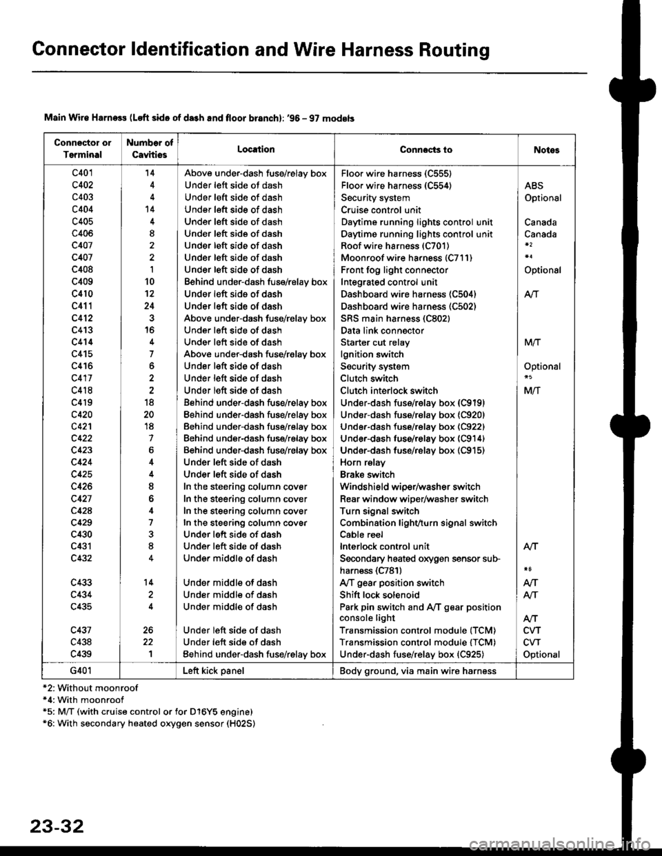
Connector or
Terminal
Number of
CavhiosLocationConnocts ioNotes
c401
c402
c403
c404
c405
c406
c407
c407
c408
c409
c410
c411
c412
c413
c414
c415
c416
c417
c418
c4l9
c420
c42'l
c423
c424
c425
c426
c427
c42A
c429
c430
c431
c432
c433
c434
c435
c431
c438
c439
'14
't4
I
I
10't2
24
16
7
o
18
20
18
7
6
I
o
4
7
8
14
1
Above under-dash fuss/relay box
Under left side ot dash
Under left sid€ of dash
Under left side of dash
Under left side of dash
Und€r left side of dash
Under left side of dash
Under left side of dash
Under left side of dash
Behind under-dash fuse/relay box
Under left side of dash
Under left side of dash
Above under-dash fuse/relay box
Under left side of dash
Under left side of dash
Above under-dash fuse/r€lay box
Under left side of dash
Under left side of dash
Under left side of dash
Behind under-dash fuse/relay box
Eehind under-dash fuse/relay box
Behind under-dash fuse/relay box
Behind under-dash fuse/relay box
Behind under-dash fuse/relay box
Under left side of dash
Under left side of dash
In the steering column cover
In the steering column cover
In the steering column cover
In the steering column covEr
Under left side of dash
Under left side of dash
Under middle of dash
Under middle of dash
Under middle of dash
Under middle of dash
Under left side of dash
Under left side of dash
Eehind under-dash fus€/relay box
Floo. wire harness (C555)
Floor wire harness (C554)
Security system
Cruise control unit
Daytime running lights control unit
Daytime running lights control unit
Roof wire harness (C701)
Moonroof wire harness (C7l1)
Front fog light connector
Integrated control unit
Dashboard wire harness (C504)
Dashboard wire harness (C502)
SRS main harness (C802)
Data link connector
Starter cut relay
lgnition switch
Security system
Clutch switch
Clutch interlock switch
Under-dash fuss/relay box (C9191
Undor-dash fuse/r€lay box {C920)
Under-dash tuse/relay box (C922)
Under-dash luse/relay box (C914)
Under-dash fuse/rBlay box (C915)
Horn relay
Brake swilch
Windshield wiper/washer switch
Rear window wiper/washer switch
Turn signal switch
Combination lighvturn signal switch
Cable reel
lnterlock control unit
Secondary heated oxygen sensor sub-
harn€ss (C781)
Ay'T gear position switch
Shift lock solenoid
Park pin switch and Ay'T gear position
console light
Transmission control module (TCM)
Transmission control module {TCM)
Under-dash fuse/relay box {C925)
ABS
Optional
Canada
Canada
Optional
Atr
MTT
Optional
Mlf
NT
Atf
CVT
CVT
Optional
AN
Atr
G401Left kick panelBody ground, via main wire harness
Main Wir€ Harness (Loft side of da3h and floor branch): '96 - 97 models
*2:Without moonroof*4: With moonroof*5: M/T (with cruise control or for D16Y5 engine)*6: With secondary heated oxygen sensor (H02S)
23-32
Page 1504 of 2189

Connector ldentification and Wire Harness Routing
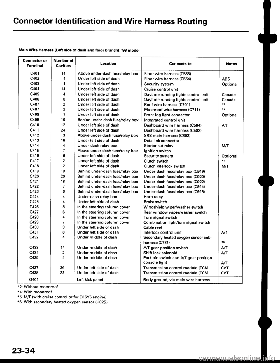
Connoctor or
Tgrminal
Number of
CavitiesLocationConneqts toNot€s
c401
c402
c403
c404
c405
c406
c407
c407
c408
c409
c410
c411
c4't2
c413
c414
c415
c416
c417
c418
c419
c420
c421
c422
c423
c424
c425
c426
c427
c428
c429
c430
c431
c432
c433
c434
c435
c437
c438
't4
l4
8,
1
10
12
24
7
6
18
20
18
7
6
8
7
8
14
2
Above under-dash fuse/relay box
Under left side of dash
Under left side of dash
Under left side of dash
Under left side of dash
Under left side of dash
Under left side of dash
Under left side of dash
Under left side of dash
Behind under-dash fuss/relay box
Under left side of dash
Under left side of dash
Above under-dash fuse/relay box
Under left side of dash
Under-dash relay box
Above under-dash fuse/relay box
Under left side of dash
Under left side of dash
Under left side of dash
Eehind under-dash fuse/relay box
Behind under-dash fuse/relay box
Behind under-dash fuse/relay box
Behind under-dash fuse/rslay box
Behind under-dash fuse/relay box
Under-dash relay box
Under left side of dash
In the steering column cover
In the steering column cover
In the steering column cover
In the steering column cover
Under left side of dash
Under left side of dash
Under middle of dash
Under middle of dash
Under middle of dash
Under middle of dash
Under left side of dash
Under left side of dash
Floor wire harness (C555)
Floor wire harness (C554)
Security system
Cruise control unit
Daytime running lights control unit
Daytime running lights control unit
Roof wiro harness (C7011
Moonroof wire harness (C711)
Front fog light connector
Integrated control unit
Dashboard wire harness (C504)
Dashboard wire harness (C502)
SRS main harness (C802)
Data link connector
Starter cut relay
lgnition switch
Security system
Clutch switch
Clutch inlerlock switch
Under-dash fuse/relay box (C919)
Under-dash fuse/relay box (C920)
Under-dash fuse/relay box (C922)
Under-dash fuse/relay box (C914)
Under-dash fuse/relay box (C915)
Horn relay
Brake switch
Windshield wiper/washer switch
Rear window wiper/washer switch
Turn signal switch
Combination light/,turn signal switch
Cable reel
lnterlock control unit
Secondary heated orygen sensor sub-
harness (C781)
Ay'T gear position switch
Shift lock solenoid
Park pin switch and Aff gear position
console light
Transmission control module (TCMI
Transmission control module (TCM)
ABS
Optional
Canada
Canada
Optional
M
MIT
Optionsl
MlT
Alr
NT
NT
CVT
CVT
G401Left kick panelBody ground, via main wire harness
Main Wire Harn€ss {Left side ot dash and floor branchl: '98 model
*2: Without moonroof*4:With moonroof*5: M/T (with cruise control or for D16Y5 engine)*6: With secondary heated oxygen sensor (H02S)
23-34
Page 1817 of 2189

Contents
How to Use This Manual ICircuit Schematics (see Circuit Index)Fuse/Relaylnformation 6Ground-to-Componentslndex 6-6ComponentLocationPhotooraohs 201Conriector Views 202
Circuit Index
Accessory power socket 155Air conditionerAir delivery'96198 models 61'99-'00 models 61-2Blower controls'96198 models 60'99100 models 60-1Compressor controls 62Fans 63Anti-lock brake system (ABS) 44A/T gear position indicatorCVT 89All except CVT 89-1Automatic transmission controlsAll '96-'98 models except CVT and GX 39All '99100 models except CVT 39-8All GX models 39-8'96-'�98 CVT 39-4'99100 cw 39-12Back-up lightsCoupe and Sedan 110Hatchback l'10-1Brake lightsAll Coupes and'96-'98 Sedans 110-15'99-'00 Sedans 110-16Hatchback 110-17Brake system indicator light'96198 models 7'1'99100 models 71-1Ceiling light 114-3Charging system 22Condenser fan 63Console lights 114Cruise control 34Dash lights 114Daytime running lights 110- 13Engine coolant temperature gauge 81-1Fog lights 110-10Front parking lights 110-2Fuel gauge 81-1Fuse/relay boxUnder-dash 6Under-hood 6-4Underhood ABS 6-3Gauges 81Ground distribution 14Ground-to-Componentslndex 6-6Hazard warning lightsAll except '99100 Sedans 110-6'99100 Sedans 110-8Headlights 110-12Headlight switch 100Heater - See Air ConditionerHorn'96197 models 40'98 model 40-1'99100 models 40-2lgnition key reminder 73lgnition systemAll '96198 models except Dl685 20All '99100 models except D16Y5 with Mn 2O-2All D1685 engines 20-2'99-'00 D 16Y5 with M/T 20
lndicators 80Integrated control unit 70lnterlock systemAll except'96J98 CVT 138'96198CVT 138-1License plate lightsAll Coupes and '96-'98 Sedans I l0-3'99100 Sedans 1 10-4Hatchback 110-5Low fuel indicator light 74Moonrool'96197 models |22'98-'00 models 122-1Odometer 81Oil pressure indicator light 80-3Power distributionBattery to ignition switch, fuses, and relaysFuses to relays and components 10-2Power door locksAll models without keyless entry 130'96-'98 models with keyless entry 130-2'99100 models with keyless entry 130-12Power mirrorsWithout detogger 141With defogger '141-2
Power windows 120Programmed fuel injection system (PGNr-Fl)All '96-98 models except D1685 23All '99-'00 models except D16Y5with M/T and D1685 24All D1685 engines 25'99100 D16Y5 with M/T 23Radiator fan 63Rear window defogger'96-,98 models 64'99100 models 64-1Seat belt reminder 73Security system'96.'98 USA HX, LX, EX 133'96-'98 Canada EX, Si 133'99TOO USA HX, LX, EX, DX.V Si 133-4'99100 Canada EX, Si 133-4All CX and DX models 133-8Speedometer 81Starting systemA./T (All except Dl685) 21A"/r (D16Bs) 21-1Manualtransmission 21-2Slereo sound system 150Supplemental rastraint system (SRS) 47Tachometer 81TailliqhtsAllboupes and'96-'98 Sedans 110-3'99100 Sedans 1 10-4Hatchback 110-5Trunk light 114-3Turn signal lightsAll except'99100 Sedans 110-6'99-'00 Sedans 1 10-8Vehicle speed sensor (VSS) 33Wiper/washerFront 91Rear 92
10
Page 1840 of 2189

Ground-to-Components I ndex
f.,lONOTE: All ground wires are BLK unless otherwise noted.
GroundPageComponents or Circuit Grounded
Battery (BLKYEL)
Steering pump bracket
t+-rg ITransmission housing
l
G101
(-1)
G101
(-2)
14-2
and
14-3
ano
14-1
Powertrain or engine control module (PG1 and pG2 are BLK: LG1 and LG2 are
BRN/BLK), EGR control solenoid valve (CW, EGR valve and lift sensor (Dt6yS enginewith M,/T), Engine coolant temperature switch, pGM-Fl main relay, power steeringpressure switch (USA), Primary HO2S (D16Y5 engine with l\/,/T), Vehicle speed sensor,VTEC pressure switch (D16Y5/D16Y8 engines), CKF sensor (BRN/BLK), Transmission
control module (CYf) (Pc1 is BLK: LG1 is BRN/BLK)
Shielding betvveen the PCM or ECM and these components (all have BRN/BLK wires):
CKF sensor, TDC/CKP/CYP sensor. Primary and secondary heated oxygen sensors.
Knock sensor (CWDl6YB engine), Mainshaft speed sensor (AiT except CVT),
I Countershaft speed sensor (A/T except CVf)
Shielding between the TCM and these components (CVT) (all have BRN/BLK wires):
Drive pulley speed sensor, Driven pulley speed sensor, Secondary gear shaft
speed sensor
Powertrain or engine control module (PG1 and pG2 are BLK; LG1 and LGz are
BRN/BLK), EGR control solenoid valve (D16Y5 engine), EGR valve (Dt685), Engine
coolant temperature switch, Fuel pressure regulator shut-off solenoid valve (D1685),
PGM-FI main relay, Power steering pressure switch (USA), Vehicle speed sensor, VTECpressure switch (All except D16Y7 engine), CKF sensor (A
except 81642) (BRN/BLK)
Shielding between the PCM or ECM and these components (all have BRN/BLK wires):
CKF sensor, TDC/CKP/CYP sensor, Primary and secondary heated oxygen sensors,
Knock sensor (All except D16Y7 engine), i/ainshaft speed sensor (Arf except CW),
Countershaft speed sensor (A,/T except CVf), Drive pulley speed sensor (CW), Drivenpulley speed sensor (CVT), Secondary gear shaft speed sensor (CVf)
I Badiator fan motor, Right front parking/turn signat tight, Right headtight
G20214-4I Cruise control actuator, Left front parking/turn signal lights, Left headlight, Rear window
I washer motor, Windshield washer motor, Washer fluid level switch (,99-'00 Canada)
G401| +-o
and
14-7
Accessory power socket, Brake fluid level switch, Clutch interlock switch (M/T), Clutchswitch (lillT with cruise/D16Y5 engine with MfD, Combination wiper switch (Z wires),
Cruise control main switch, Cruise control unit, Dash lights brightness controller, Data
link connector, Daytime running lights control unit (Canada), Gauge assembly, Horn('96-'97 models), Integrated control unit, Interlock control unit (ArI), Keyless door lock
control unit ('99-'00 models with keyless), Moonroof close and open relays, Moonroof
switch, Park pin switch (A/r), Power window relay, Rear window defogger relay, Rear
window defogger switch ('96-'98 models), Steering lock, Stereo radio tuner (,96-,98
USA: LX, EX, and HX), Turn signal/hazard relay, Windshield wiper motor.....plus
everything grounded through G402
6-6