1998 HONDA CIVIC idle control
[x] Cancel search: idle controlPage 374 of 2189

3.
5.
6.
1.
Fuel Cut-off Control
. During deceleration with the throttle valve closed, current to the fuel injectors is cut off to improve fuel economy at
speeds over the following rpm:. D16Y5 engine (M/T):850 rpm. D]6Y5 engine (CVT), D'16Y8 engine (USA M/T): 920 rpm
. Dl6Y8 engine (USA A,/I), D16Y7 engine (USA A,/T);910 rpm
. D16Y8 engine (Canada M/T), D16Y7 engine (canada): 990 rpm
' D16Y8 engine (Canada M/T): 1,000 rpm
. 816A2 engine: 970 rpm
. Fuel cut-off action also takes place when engine speed exceeds 6,900 rpm (D16Y5, D16Y7 engine; D'16Y8 engine:
7,000 rpm. 816A2 engine: 8.100 rpm), regardless of the position of the throttle valve, to protect the engine from
over-rewing. With '99 Dl6Y7 engine (A,/T) and '99 D16Y8 engine (A./T), the PCM cuts the fuel at engine speeds over
5,000 rpm when the vehicle is not moving.
IVC Compressor Clutch Relay
When the ECM/PCM receives a demand for cooling from the air conditioning system, it delays the compressor from
being energized, and enriches the mixture to assure smooth transition to the A,/C mode
Evaporative Emission (EVAP) Purge Control Solenoid Valve*'
When the engine coolant temperature is above 154'F (68'C). the ECM/PCM controls the EVAP purge control solenoid
valve which controls vacuum to the EVAP purge control canister.
Evaporative Emission (EVAP) Purge Control Solenoid Valve*a
When the engine coolant temperature above 154"F (68"C), intake air temperature above 32"F (0'C) and vehicle speed
above 0 mile (0 km/h) or [Ay'C compressor clutch on and intake air temperature above 160"F (41'C)], the ECM/PCM
controls the EVAP purge control solenoid valve which controls vacuum to the EVAP purge control canister.
Exhaust Gas Recirculation (EGR) Control Solenoid Valve*?
When EGR is required for control of oxides of nitrogen (NOx) emissions. the ECM controls the EGR control solenoid
valve which supplies regulated vacuum to the EGR valve
Alternator Control
The system controls the voltage generated at the alternator in accordance with the electrical load and driving mode,
which reduces the engine load to improve the fuel economy.
ECM/PCM Fail-safe/Back-up Functions
1. Fail safe Function
When an abnormality occurs in a signal from a sensor, the ECM/PCM ignores that signal and assumes a pre-pro-
grammed value for that sensor that allows the engine to continue to run.
2. Back-uD Function
When an abnormality occurs in the ECM/PCM itself, the fuel injectors are controlled by a back-up circuit independent
of the system in order to permit minimal driving.
3. Self diagnosis Function lMalfunction Indicator Lamp (MlL)l
When an abnormality occurs in a signal from a sensor, the ECM/PCM supplies ground for the lvllL and stores the DTC
in erasable memory. When the ignition is initially turned on, the ECM/PCM supplies ground for the MIL for two sec-
onds to check the MIL bulb condition.
4. Two Trip Detection Method
To prevent false indications, the Two Trip Detection Method is used for the HO2S, fuel metering-related. idle control
system, ECT sensor, EGR system and EVAP control system self-diagnostic functions. When an abnormality occurs,
the ECM/PCM stores it in its memory. When the same abnormality recurs after the ignition switch is turned OFF and
ON 0l) again, the ECM/PCM informs the driver by lighting the MlL. However, to ease troubleshooting, this function is
cancelled when you jump the service check connector. The MIL will then blink immediately when an abnormality
occurs,
5. Two (or Three) Driving Cycle Detection Method
A "Driving Cycle" consists ot starting the engine. beginning closed loop operation, and stopping the engine. lf misfir-
ing that increases emissions is detected during two consecutive driving cycles, or TWC deterioration is detected dur-
ing three consecutive driving cycles, the ECM/PCM turns the MIL on. However, to ease troubleshooting, this function
is cancelled when you jump the service check connector. The MIL will then blink immediately when an abnormality
occurs.
(cont'd)
1 1-1 05
.1.
Page 459 of 2189

ldle Control System
System Description
The idle speed ot the engine is controlled by the ldle Air Control (lAC) Valve.The valve changes the amount of air bypassing into the intake manifold in response to electric current controlled bv theECM/PCM. When the IAC Valve is activated, the valve opens lo maintain the proper idle speed.
D16Y5, D16Y8, Br6A2 engine (M/T):
(ROTARYItac vat-vEEI{GINEcooLAI{T
VARIOUSsEI{SORS
VARIOUSSENSORS
INTAKE MANIFOTDDl6Ys {CVTl, D16Y8 engine lA/T):
D16Y7 engine:
{ROTABY)
;iy--, - ---
11-190
Page 460 of 2189

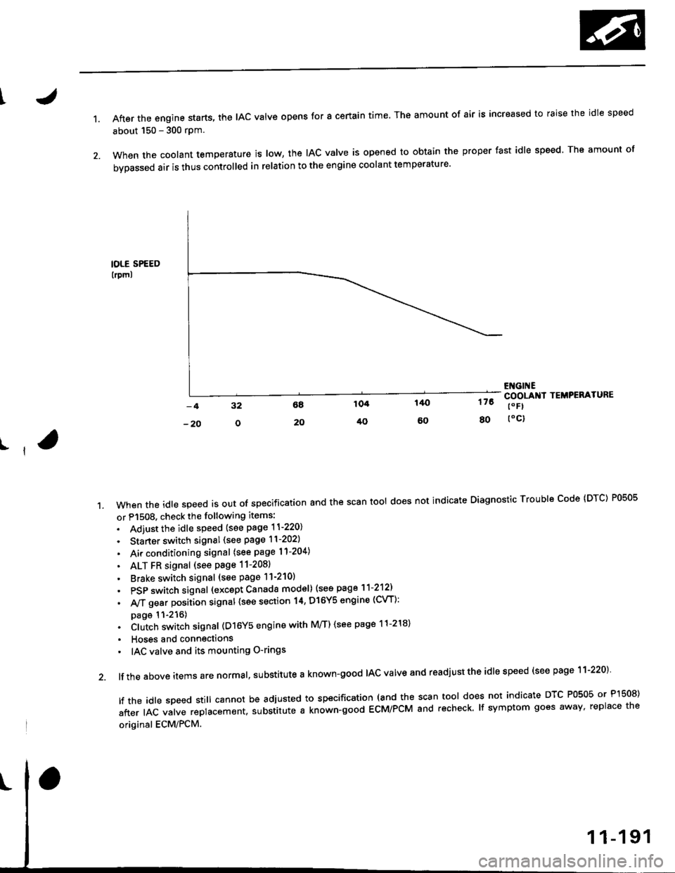
1.After the engine starts, the lAc valve opens for a certain time. The amount of air is increased to raise the idle speed
about 150 - 300 rpm.
When the coolant temperature is tow, the IAC valve is opened to obtain the proper fast idle speed. The amount of
bypassed air is thus controlled in relation to the engine coolant temperature'
IOLE SPEED
lrpml
176
80
ENGI ECOOLANI TEMPERATURE
t" Fl
toc)
ll
't.Whentheid|espeedisoutofspeciiicationandthescantoo|doesnotindicateDiagnosticTroub|ecode(DTc)P0505
or P1508. check the following items:
. Adiust the idle speed {see page 11-220}
. Starter switch signal (see page 11-202)
. Air conditioning signal (see page l1-204)
. ALT FR signal (see Page 11-2081
' Brake switch signal (see page 11-210)
. PSP switch signal (excapt Canada model) (see page 11-212)
. A,/T gear position signal {see section 14, Dl6Y5 engine (CVT):
page 11-216). Clutch switch signal (D16Y5 engine with M/T) (see page 11-218)
. Hoses and connections
' IAC valve and its mounting O-rings
lf the above items are normal, substitute a known-good IAC valve and readjust the idle speed (see page 11-220)
|ftheid|espeedsti||cannotbeadjustedtospecification(andthescantoo|doesnotindicateDTcP0505orP]50S)
after IAC valve replacement. substitute a known-good ECM/PCM and recheck. lf symptom goes away, replace the
original ECM/PCM.
Page 461 of 2189

ldle Control System
ldle ControlSystem
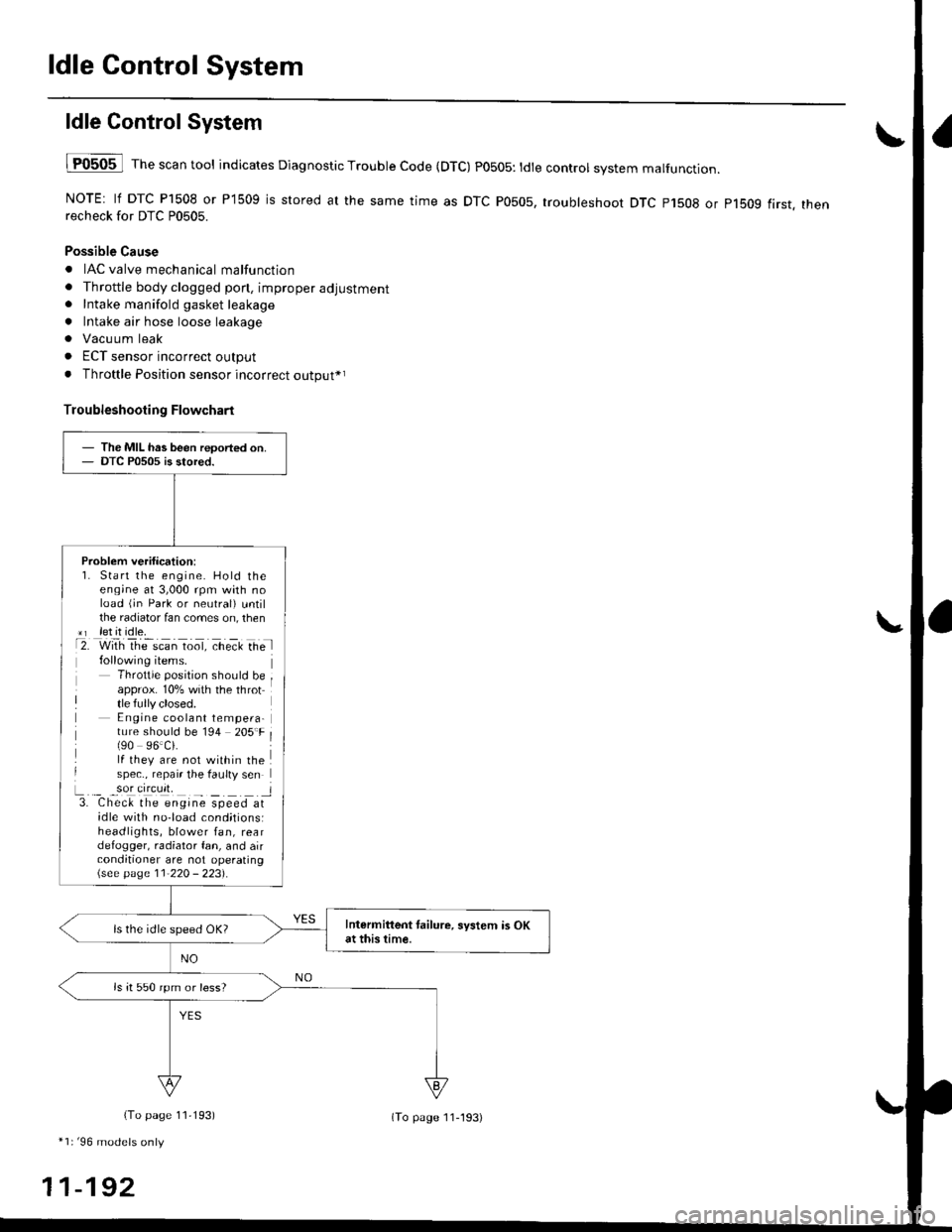
lF0505 l Th" """n tool indicates Diagnostic Trouble Code (DTC) PO5O5: tdte controt system malfunction.
NOTE: lf DTC P1508 or P1509 is stored at the same time as DTC P0505, troubleshoot DTC p1508 or p1bog first. thenrecheck for DTC P0505.
Possible Cause
. IAC valve mechanical malfunction
. Throttle body clogged pon, improper adjustment. Intake manifold gasket leakage
. Intake air hose loose leakage
. Vacu um leak
. ECT sensor incorrect output
. Throttle Position sensor incorrect output*r
Troubleshooting Flowchart
The MIL has been reoorted on.DTC P0505 is stored.
Problem verification:1. Start the engine. Hold theeng;ne at 3,000 rpm with noload (jn Park or neutral) untilthe radiator fan comes on, then*r let it idle.t2. with rhe scan toot, ct'eit Ge l
Throttle position should beapprox. 10% with the throttle fully closed.E ngine coolant tempera-ture should be 194 205'F(90 96.Ci.lf they are not within thespec., repair the faulty sen
L._ _9oI9[cr]41 l3. Chec& the engine speed atidle with no-load cond;tionsiheadlights, blower fan, reardefogger, radiator fan, and airconditioner are not operating\see page l1-22O - 223).
Intermittent tailure, system is OKat this time.ls the idle speed OK?
ls it 550 rpm or less?
(To page 11,193)
*1r'96 models only
11-192
(To page ll-193)
Page 463 of 2189

ldle Control System
ldle Air Control (lACl Vatve ('96 - 98 Dl6ys, Dl6yB engine with M/Tl
The scan tool indicates Diagnostic Trouble Code (DTC) P1508: A problem in the ldle Air Controt flAC) varvecircuit.
The IAC Valve changes the amount of air bypassing the throttle body in response to a current signal from the ECM inorder to maintain the proper idle speed.
IAC VALVE 2P CONNECTOR ICl3A)
,flrcerh-:J iYEL/BLKI
!.__-,/ -lt(v)
-T-=
Wire side of female terminals
tAcv(BLK/
ELUI
ECM CONNECTOR A I32PI
Wire side oI lemal€ terminals
VALVE
6a10ll12t3r5t6l7t8t920232a
t*25&a2A3o
The MIL hss b€on repo.ted on.DTC P'l508 i. itorod.
Problem vorification:1. Do the ECM/PCM Reset Pro-cedure,Start the engine, and warm ituP to normal operating tem-perature.
Intormittont t!llur., sy.tcm b OKat thb tim6. Chsck fol poor con-ncctionr or loo3e wirot at C138(lAC valv.l.nd ECM.
ls DTC P1508 indicated?
Check for an opcn in the wiro(lGPl line):1. Turn the ignition switch OFF.2. Disconnect the IAC valve 2Pconnector.3. Turn the ignition switch ON (ll).
4. Measure vohage between bodyground and the IAC valve 2Pconnectorterminal No. 2.
R.prir opan in the wiro botwa.nIAC valv..nd PGM-FI main r.l.y.
Chock for an opon or sho in thewire (IACV linal:1. Turn the ignition switch OFFand reconnect the IAC valveconnector.2. Disconnect the ECM connectorA (32P).
3. Turn the ignit;on switch ON (ll).4. Measure voltage betweenbody ground and ECM con-nector terminal A12.
(To page 1l-195)
11-194
Page 465 of 2189
![HONDA CIVIC 1998 6.G Workshop Manual ldle Gontrol System
ldle Air Control (lAG) Valve (99 - 00 Dl6Y8 engine with M/T, Bt6A2 enginel
[Fl50g l ]h" scan tool indicates Diagnostic Trouble Code (DTC) P1508: A problem in the ldle Air Controt HONDA CIVIC 1998 6.G Workshop Manual ldle Gontrol System
ldle Air Control (lAG) Valve (99 - 00 Dl6Y8 engine with M/T, Bt6A2 enginel
[Fl50g l ]h" scan tool indicates Diagnostic Trouble Code (DTC) P1508: A problem in the ldle Air Controt](/manual-img/13/6068/w960_6068-464.png)
ldle Gontrol System
ldle Air Control (lAG) Valve ('99 - 00 Dl6Y8 engine with M/T, Bt6A2 enginel
[Fl50g l ]h" scan tool indicates Diagnostic Trouble Code (DTC) P1508: A problem in the ldle Air Controt AC) vatve- CtrCUtt.
The IAC Valve changes the amount of air bypassing the throttle body in response to a current signal from the ECM inorder to maintain the proper idle speed.
IAC VALVE 2P CONNECTOR IC138'
la rcprI - {YEL/8LKI 2t--d,
Y-=
Wire side ot female terminals
Wire side of lemale terminals
VALVE
The MIL has boon r€oorted on.DTC P1508 is srored.
Probl6m verification:1. Do the ECM/PCM Reset Pro-cedure.2. Start the engine, and warm itup to normal operating lem-perature.
Intermittent tailure, system is OKat this timg. Check to. poor con-noctions or loose wires at C138{lAC valvel and ECM.
ls DTC P1508 indicated?
Ch6ck for an open in the wir€{lGPl lino}:1. Turn the ignition switch OFF.2. Disconnect the IAC valve 2Pconnector.3. Turn the ignition switch ON (ll).
4. Measure voltage between bodyground and the IAC valve 2Pconneclor termina I No.2,
Repair opon in the wire bgtwoenIAC valve and PGM-Fl main relay.
Check tof an open or short in thewire {IACV line}l1. Turn the ignition switch OFFand reconnect the IAC valve
2. Disconnect the ECM connectorB {25P).3. Turn the ignition switch ON (ll).
4. Measure voltage betweenbody ground and ECM conn€ctor terminal 823.
(To page 11-197)
1 1-1 96
Page 467 of 2189

ldle Control System
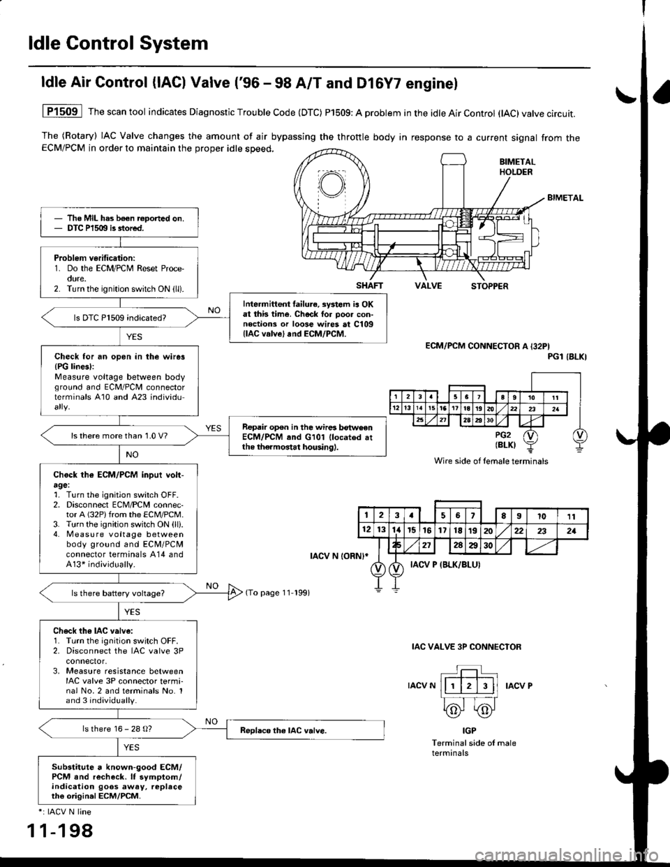
ldle Air Control (lAC) Valve ('96 - 98 A/T and Dl6Y7 enginel
The (Rotary) IAC Valve changes the amount of air bypassing the throttle body in response to a current signal from theECM/PCM in order to maintain the proper idle speed,
BIMETAL
VALVESTOPPER
1P1509 Thescantool indicates Diagnostic Trouble Code (DTC) P1509: A problem in the idle Air Control (tAC)valve circuit.
ECM/PCM CONNECTOR A I32PIPGl IBLKI
IAC VALVE 3P CONNECIOR
IACV NIACV P
IGP
Terminal side of maleterminals
*: IACV N line
1 1-198
The MIL has b€€n roported on.DTC P1509 is stored.
Problem verification:1. Do the ECM/PCM Reset Proce-oure.2. Turn the ignition switch ON (ll).
Intermittent failura, systom ia OKat this time. Check tor poo. con-noctions or loose wires at C109llAC valve) and ECM/PCM.
ls DTC P1509 indicated?
Check for an opon in the wirer{PG lines):Measure voltage between bodvground and ECM/PCII connectorterminals A10 and A23 individu
Repair op€n in the wires betwoenECM/PCM and G101 llocated attho thermostat housing).
ls there more than 1.0 V?
Chock th€ ECM/PCM inpui volt-agel1. Turn the ignition switch OFF.2. Disconnect ECM/PCM connec-tor A (32P)from the ECM/PCM.3. Turn the ignition switch ON (ll).4. Measu re voltage betweenbody ground and ECM/PCMconnector terminals A14 andA13* individually.
Ch6ck th6 IAC valve:1. Turn the ignition switch OFF.2. Disconnect the IAC valve 3Pconnector,3, Measure resistance betweenIAC valve 3P connector termi-nal No.2 and terminals No. 1and 3 individually.
ls there 16 - 28 g?
Substitute a known-good ECM/PCM and recheck. lf symptom/indication goos away, replaceth€ origin.l ECM/PCM.
SHAFT
rAcv N loRNl*
(To page 11-199)
Wire side of lemale terminals
123a56El011
121314r5161718t9202:22321
272AA30
IACV P {BLK/BLUI
Page 469 of 2189

ldle Gontrol System
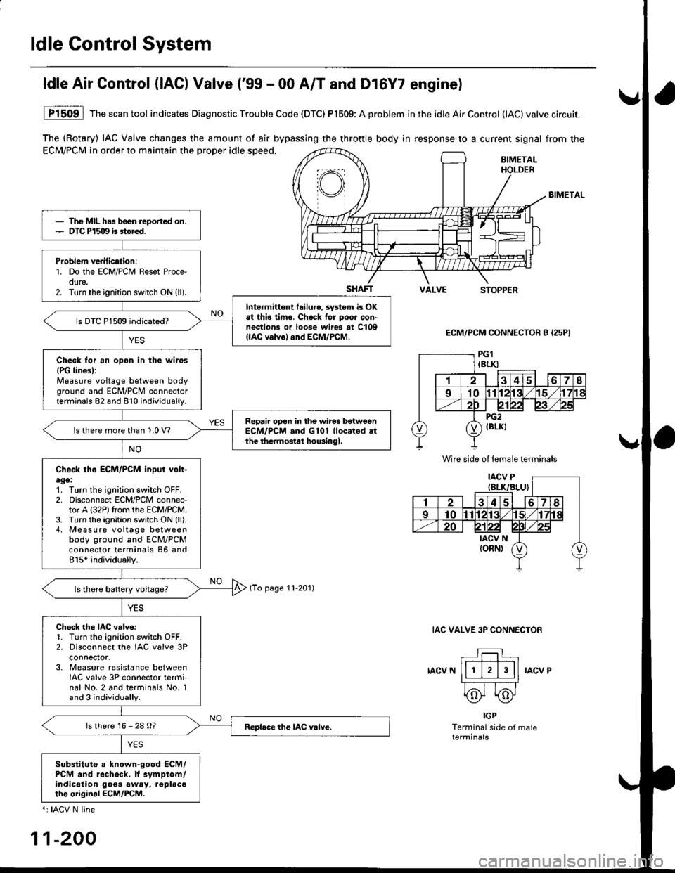
The (Rotary) IAC Valve changes the amount of air bypassing the throttle body in response to a current signal from the
ECM/PCM in order to maintain the proper idle speed.BIMETALHOLDER
BIMETAL
SHAFTVALVESTOPPER
ECM/PCM CONNECTOR B {25P}
(To page 11-201)
IAC VALVE 3P CONNECTOR
IACV NIACV P
ldle Air Control {lACl Valve ('99 - 00 A/T and Dl6Y7 enginel
YES
1P1509 lThescantool indicates Diagnostic Trouble Code (DTC) P1509:A problem inthe idleAirControl (lAC)valve circuit.
IGP
Terminal side of maleterminals
Sub3titute e known-good ECM/PCM .nd recheck. lf 3vmptom/indicalion goos away, replac6thc original ECM/PCM.
*: IACV N line
11-200
Tho MIL has b€en reported on.OTC P1509 is sto.ed.
Problem verilicationr1. Do the ECM/PCM Reset Proce-dure.2. Turn the ignition switch ON (ll).
Intermittont tailure, sy3tem i3 OKat thb time. Check for poor con'noctions or loose wiros at C109(lAC velvel and ECM/PCM.
ls DTC P1509 indicated?
Check for an oDen in the wilosIPG linesl:Measure voltage between bodyground and ECM/PCM connectorterminals 82 and 810 individually.
Ropail open in the wires be'tw€enECM/PCM .nd G101 llocated .tthe the.mostat housingl.ls there more than 1.0 V?
Check tho ECM/PCM input volt-age:1. Turn the ignition switch OFF.2. Disconnect ECM/PCM connec-tor A (32P)trom the ECM/PCM.3. Turn the ignition switch ON (ll).
4, Measure voltage betweenbody ground and ECM/PCMconnector terminals 86 and815* individually.
Chock the IAC v.lve:1. Turn the ignition sw;tch OFF.2. Disconnect the IAC valve 3Pconnoctor.3. Measure resistance betweenIAC valve 3P connector termi'nal No. 2 and terminals No. 1and 3 individually.
ls there 16 - 28 O?
Wire side of female terminals