1998 HONDA CIVIC combination light switch
[x] Cancel search: combination light switchPage 1745 of 2189
Precautions/ Procedures
)General Precautions
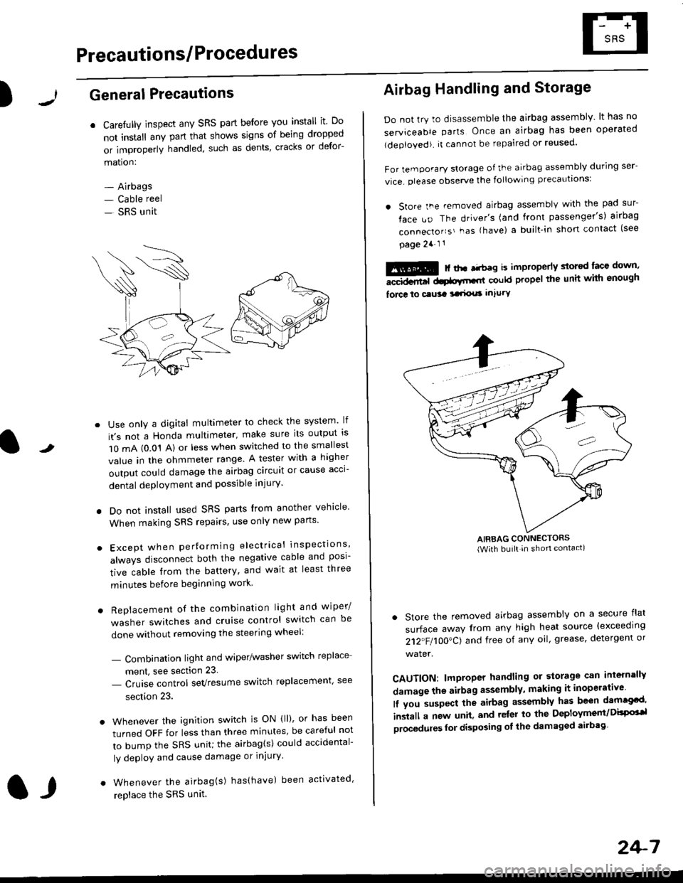
r Carefully inspect any SRS part before you install it Do
not install any part that shows signs of being dropped
or improperly handled' such as dents, cracks or defor-
mation:
- Airbags- Cable reel
- SRS unit
-
Use only a digital multimeter to check the system lf
it's not a Honda multimeter, make sure its output ls
1O mA (0.01 A) or less when switched to the smallest
value in the ohmmeter range. A tester with a higher
output could damage the airbag circuit or cause acci-
dental deployment and possible injury'
I Do not install used SRS parts from another vehicle
When making SRS repairs, use only new pans'
) Except when performing electrical inspections'
always disconnect both the negative cable and posl-
tive cable from the battery, and wait at least three
minutes before beginning work
r Replacement of the combination light and wiper/
washer switches and cruise control switch can be
done without removing the steering wheel:
- Combinalion light and wiper/washer switch replace
ment, see section 23
- Cruise control sevresume switch replacement' see
section 23.
. Whenever the ignition switch is ON {ll), or has been
turned OFF for less than three minutes' be careful not
to bump the SRS unit; the airbag(s) could accidental-
ly deploy and cause damage or injury'
. Whenever the airbag{s) has(have) been activated'
replace the SRS unit.l,
2+7
Airbag Handling and Storage
Do not try to disassemble the airbag assembly. lt has no
serviceable parts Once an airbag has been operated
(deployed). it cannot be repaired or reused'
For temporary storage of the airbag assembly during ser-
vice. olease observe the following precauttons:
. store the .emoved airbag assemblv with the pad sur-
face uo The driver's (and front passenger's) airbag
connecto''s'-as {have) a built.in short contact (see
page 2a-l 1
: | ..r r-+r-a k imninncrlv slorcd lace down,-""dd.r6t dtatltt-,tl could propel the unit whh enough
force lo c.usa 3a.ix! intury
AIRBAG CONNECTORS(With built in shon contact)
. Store the removed airbag assembly on a secure flat
surface away from any high heat source {exceeding
212"FI1OO"CJ and free of any oil' grease, detergent or
water.
CAUTION: lmproper handling or storage can intern'lJy
damage the airbag assembly, making it inoperativo
lf you suspect the airbag assembly has been dam€cd'
inslall a new unit. and relsr lo the Deployment/DisPG'l
olocedules for disposing ol the damaged airbag
Page 1840 of 2189

Ground-to-Components I ndex
f.,lONOTE: All ground wires are BLK unless otherwise noted.
GroundPageComponents or Circuit Grounded
Battery (BLKYEL)
Steering pump bracket
t+-rg ITransmission housing
l
G101
(-1)
G101
(-2)
14-2
and
14-3
ano
14-1
Powertrain or engine control module (PG1 and pG2 are BLK: LG1 and LG2 are
BRN/BLK), EGR control solenoid valve (CW, EGR valve and lift sensor (Dt6yS enginewith M,/T), Engine coolant temperature switch, pGM-Fl main relay, power steeringpressure switch (USA), Primary HO2S (D16Y5 engine with l\/,/T), Vehicle speed sensor,VTEC pressure switch (D16Y5/D16Y8 engines), CKF sensor (BRN/BLK), Transmission
control module (CYf) (Pc1 is BLK: LG1 is BRN/BLK)
Shielding betvveen the PCM or ECM and these components (all have BRN/BLK wires):
CKF sensor, TDC/CKP/CYP sensor. Primary and secondary heated oxygen sensors.
Knock sensor (CWDl6YB engine), Mainshaft speed sensor (AiT except CVT),
I Countershaft speed sensor (A/T except CVf)
Shielding between the TCM and these components (CVT) (all have BRN/BLK wires):
Drive pulley speed sensor, Driven pulley speed sensor, Secondary gear shaft
speed sensor
Powertrain or engine control module (PG1 and pG2 are BLK; LG1 and LGz are
BRN/BLK), EGR control solenoid valve (D16Y5 engine), EGR valve (Dt685), Engine
coolant temperature switch, Fuel pressure regulator shut-off solenoid valve (D1685),
PGM-FI main relay, Power steering pressure switch (USA), Vehicle speed sensor, VTECpressure switch (All except D16Y7 engine), CKF sensor (A
except 81642) (BRN/BLK)
Shielding between the PCM or ECM and these components (all have BRN/BLK wires):
CKF sensor, TDC/CKP/CYP sensor, Primary and secondary heated oxygen sensors,
Knock sensor (All except D16Y7 engine), i/ainshaft speed sensor (Arf except CW),
Countershaft speed sensor (A,/T except CVf), Drive pulley speed sensor (CW), Drivenpulley speed sensor (CVT), Secondary gear shaft speed sensor (CVf)
I Badiator fan motor, Right front parking/turn signat tight, Right headtight
G20214-4I Cruise control actuator, Left front parking/turn signal lights, Left headlight, Rear window
I washer motor, Windshield washer motor, Washer fluid level switch (,99-'00 Canada)
G401| +-o
and
14-7
Accessory power socket, Brake fluid level switch, Clutch interlock switch (M/T), Clutchswitch (lillT with cruise/D16Y5 engine with MfD, Combination wiper switch (Z wires),
Cruise control main switch, Cruise control unit, Dash lights brightness controller, Data
link connector, Daytime running lights control unit (Canada), Gauge assembly, Horn('96-'97 models), Integrated control unit, Interlock control unit (ArI), Keyless door lock
control unit ('99-'00 models with keyless), Moonroof close and open relays, Moonroof
switch, Park pin switch (A/r), Power window relay, Rear window defogger relay, Rear
window defogger switch ('96-'98 models), Steering lock, Stereo radio tuner (,96-,98
USA: LX, EX, and HX), Turn signal/hazard relay, Windshield wiper motor.....plus
everything grounded through G402
6-6
Page 1988 of 2189
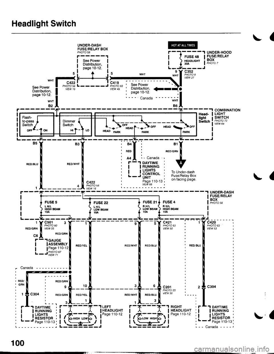
Headlight Switch
(
UNOER-OASHFUSEiRELAY BOXPHOTO 58
Sse PowerDisiribution,page 10-12-
UNDER-HOODFUSE/RELAYBOX
H
FUSE 22L H/ILOIY SEAflt0a
COMBINATIONLIGHTswtTcHHead-lightSwltch
L-----J'SeePower' Distribution,
: Page 10-12.
a
{
UNDER-DASHFUSE/RELAYBOXFUSS 2tF H/LLOW EgAtl
FUSE 4R TIILHIG|{ AEAMt0A
vtEw 53
_ ___:==
1-sr*r"
_
l_-.__
_,_.
it:
".0-", i ".o ".u I i ".o u.,
iti
Iti
llr
lli
lli
--'l --u{.sao,l,. i 2
neourrr I nroerul'/Ftr'o :---,
,.|,___ui
il--Tll''%i'sr"' ii
it@4li**"""li-; s-i5-r i .
I
I
i-t-;;l
1 J lff*n"' IL-.J----J
nrrl'?;Ii
ffif'illi! i
*itn12
HI
- - ) ot[*o1- -] ot. "roo a]ot.HEAD PAnK I panx IPAnK
!a
- -I DAYTIME
IRUNNINGI LIGHTS
! RESTSTOR'- Paqe 110-13
100
Page 1999 of 2189
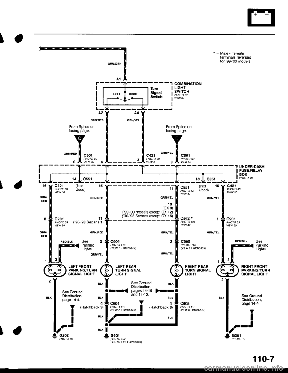
\
*=l\4ale-Female
terminals reversedfor'99-'00 models
TumSignalSwitch
From Splice orfacing page.
v
icnrineo I csor
" l"P'li'?c--
l
'f "*f B""i.Bfii'Jr'l ".^f
I see Grouno ar-< pay6!,,-,v >-ra
'|
Tt""""i*l}=J'..""."'.*�i{{?;:*
k::
*-i;,
f#::*=i
COMBINATIONLIGHTswtTcH
c423
vtEw 3
From Splice onfacing page.
v
ilo"nntt | "uo,
n I�',tr[T?'*
UNDER.DASH
I
I
/7-T LEFr FRoNr /A LEFr REAR ./A nrcxr neanI p q I PARKING/TURN I le I TURNSIGNAL I b ITURNSIGNAL
\:9./ srcNAL LrcHr \!r/ uorr r ,/ LrcHr
Y2See Ground erx IDistnbution, Ipages 14-10 >-rOand 14-12. I"'-
I 3:"":ix'5: "'iI
."oo
and 1+12 "I
I ."n.
aLK
I FUSE/RELAY
iF,?|",,
c421
vtEw50\-----'if,
u';%- l-t?'o' 10
o""n.. I
u't* o' cFN,yEL
,ol
('ee- oo moders except Cliti I{96j98 Sedans excepl GX 16} A C562. l---- -'f,
t:;?,''
o"n,^r.. I .BN'YEL
c6o4 , 1..0.'iftr",'::"""^,,, i "^1,T?l:i""."".
Onrl,rer- |
l1
L.tI
ru Y Lx%", s""1, 15
o"n, I
u't" uo
GRNTRED*"1
"
l riqrk" 1,so-,sa seoans111
ru
| aEo/BLK .""
o"n'"]
,lrtrufli'""""
c201
vtEw 30
FED/BLXSeeParkingLights
!t c2o2 4 c6ol- PHOTO 19 - PHA|A 1A2PHOIO 173 (Halchback)
110-7
Page 2053 of 2189
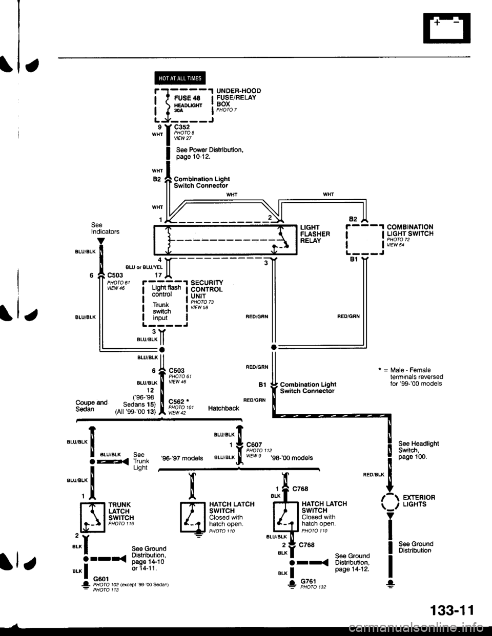
UNDER.HOODl t FUsE4s I FUSEiRELAY! xamucnr ! BoX
I I.A I PHoro 7
LJ,----Jc352
vtEw 27
Soe Pow€r Distdbulion,page 1&12,
Combination LightSwitch ConnectorE2
SeelndicatorsCOMBINATIONI I LIGHT SWITCH
| | v;iw; -
LIGHTFLASHERRELAY
4aLU or ALU/YEI
c503
iTFffiliBi+B,il:"'s#Ji"" I coNrRoL
i#$ iI input IL ----J3YBLU/BLK ll:aBrui 8rK ll
*,rlfr ftT-f.","
,^ftslllfl li^ir,, Ha,chback
vtEw 58
Coupa tndSedan
Combination LightSwitqh Connector
r = l\,lale - Femaletermrnals reversedlor'99-'00 models
See HeadlightSwiich,peg61(n.
EXTERIORLIGHTS
Seo GroundDistribution
"'u'"t*X
".u,"."aE,<
-*;"1
SeeTrunkLight
'9+ 97 models
aau,"a" fi
'*9#1",,,
BLU/BLKrf vEwe g8-,oo modets
l
qi*$qli-
TRUNKLATCHswrTcH
":^f se€ Ground
5--r< !#itl8".* I o"o'
or 14-11
.|- PHOIO ro2lorcoDr'99 oo sedan): PHofo 113
";-f "^'
FE
I-I-t HATCH LATCHI I I swtrcx
lljij::,:}#x""'*if
"tut
seecroundo tr
e.* | Page 14-12'
+ 9131",,,
133-11
Page 2108 of 2189
-
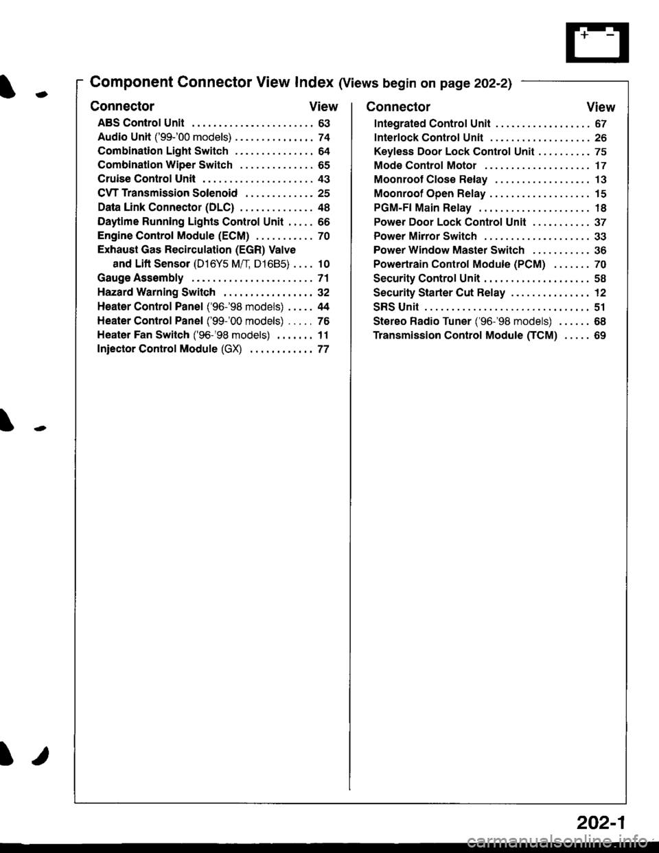
Component Connector View Index (Views begin on page 202-21
Connector View
ABS Control Unit........ ......63
Audio Unit ('99-'00 models) ......74
Combination Light Switch . . . . . . . . . . . . . . . 64
Combination Wiper Switch . . . . . . . . . . . . . . 65
Cruise Control Unit.... .....43
C\TTTransmission Solenoid ............. 25
Data Link Connector (DLC) ..... 48
Daytime Runnlng Lights Control Unit ..... 66
Engine control Module (ECM) ...........70
Exhaust Gas Recirculation (EGR) Valve
and Lift Sensor (D16Y5 Mfl, D1685) . . . . 10
Gauge Assembly .............71
HazardWarnlngSwitch,,. .,,,...,,,,... 32
Heater Control Panel ('96-'98 models) .....44
Heater Control Panel ('99-'00 models) ...., 76
Heater Fan Switch ('96-'98 models) ,,,.... 11
fniector Control Module (GX) ............77
I/
202-1
Connector View
Integrated Control Unit .......,. 67
f nterfock Control Unit .... ...... 26
Keyfess Door Lock Control Unit . . . . , . . . . . 75
Mode Control Motor ... ........'17
Moonroof Close Relay .. .......13
Moonroof Open Relay ... .......15
PGM-FI Main Relay .. .......... 18
Power Door Lock Conlrol Unil ..... ...... 37
Power Mirror Switch .,... ...... 33
Power Window Master Switch .,.........36
Powertrain Control Module (PCM) .......70
Security Control Unit ..., ..,,... 58
Security Starter Cut Belay ... ...,,,....,, 12
SRS Unit ............. 51
Stereo Radio Tuner ('96-'98 models) ...... 68
Transmission Control Module CICM) .....69
Page 2129 of 2189
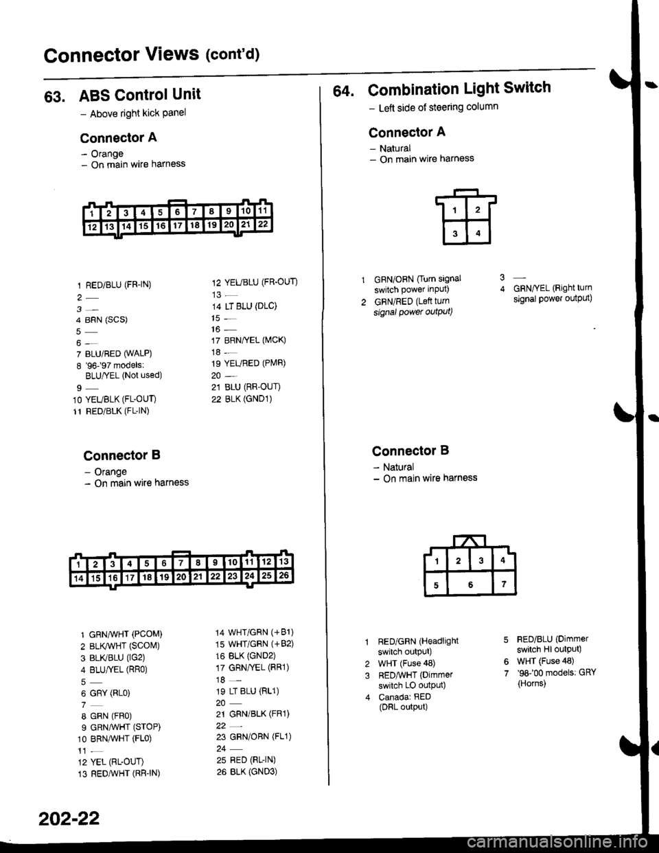
Connector Views (cont'd)
63. ABS ControlUnit
- Above right kick Panel
Connector A
- Orange- On main wire harness
1 RED/BLU (FR-|N)
3-
4 BRN (SCS)
7 BLU/BED (WALP)
8 '96197 models:
BLU|YEL (Not used)
9_
10 YEUBLK (FL-OUT)
11 RED/BLK (FL-|N)
Connector B
- Orange- On main wire harness
1 GRN^VHT (PCOM)
2 BLr(wHT {SCOM)
3 BLIVBLU (lG2)
4 BLU/fEL (RRo)
6 GRY (RLo)
8 GRN (FRo)
9 GRNAVHT (STOP)
10 BRNAVHT (FLo)
12 YEL (RL-OUT)
13 REDAVHT (RR"IN)
12 YEUBLU (FR.OUT)
14 LT BLU (DLC)
16 -
17 BRN/YEL (MCK)
18 -
19 YEURED (PlVlR)
21 BLU (RR-OUI)
22 BLK (GND1)
14 WHT/GRN (+81)
15 WHT/GRN (+82)
16 BLK {GND2)17 GRN/yEL (FRl)
18 -
19 LT BLU (RL1)
21 GRN/BLK (FRl)
22_
23 GRN/ORN (FL1)
25 RED (RL-IN)
26 BLK {GND3)
202-22
64. Combination Light Switch
- Lett side of steering column
Connector A
- Natural- On main wire harness
GRN/ORN Ourn signal
switch power input)
GRN/RED (Lett turn
signal power outqut)
3
Connector B
- Natural- On main wire harness
RED/GRN (Headlight
switch outpUt)
WHT (Fuse 48)
REDAvHT (Dimmer
switch LO outpu0
Canadar RED(DRL output)
GRN/YEL (Right turn
signal power output)
FED/BLU (Dimmer
switch Hl output)
WHT (Fuse 48)'98100 models: GRY
{Horns)
6
7
Page 2130 of 2189
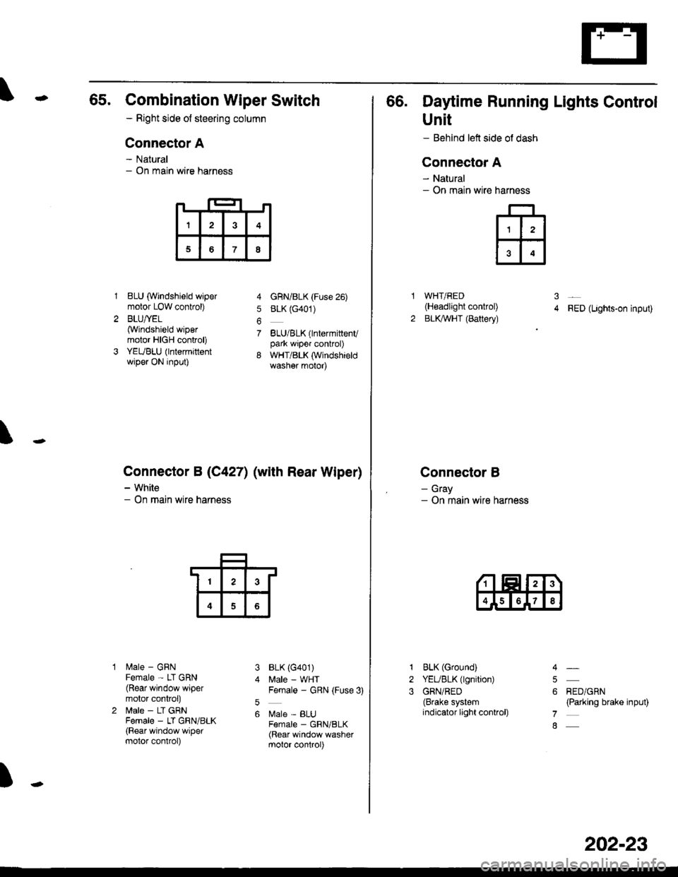
65. Combination Wiper Switch
- Right side ot steering column
Connector A
- Natural- On main wire harness
1BLU (Windshield wipermotor LOW conkol)
BLU/YEL(Windshield wipermotor HIGH control)
YEUBLU (lntermittentwiper ON input)
lilale - GRNFemale - LT GRN(Rear window wipermotor conkol)
lrale - LT GRNFema|e _ LT GRN/BLK(Rear window wipermotor control)
4 GnN/BLK (Fuse 26)
5 BLK (G401)
7 BLU/BLK(lntermittenvpark wiper control)
8 WHT/BLK (Windshieldwasher motor)
BLK (G401)
Male - WHTFemale - GRN (Fuse 3)
Male - BLUF€male _ GRN/BLK(Rear window washermotor control)
\
Connector B (C4271 (with Rear Wiper)
- White- On main wire harness
3
5
6
)
I3
68
13
4
66. Daytime Running Lights Control
Unit
- Behind left side ol dash
Connector A
- Natural- On main wire
WHT/RED(H€adlight control)
BLKAVHT (Battery)RED (Lights-on input)
Connector B
- Gray- On main wire harness
narness
ffi
31
2
1
2
3
BLK (Ground)
YEUBLK (lgnition)
GRN/RED(Brake systemindicator light conkol)
RED/GRN(Parking brake input)
4
5
6
7
8
202-23