1998 HONDA CIVIC Value
[x] Cancel search: ValuePage 708 of 2189
Description
Hydraulic Flow lcont'dl
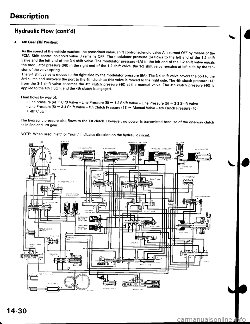
4th Goar {E Position}
As the speed of the vehicle reaches the prescribed value, shift controlsolenoid valve A is turned OFF bymeans ofthePCM Shift control solenoid valve B remains oFF. The modulator pressure (6) flows to the left end of the t-2 shiftvalve and the left end of the 3-4 shift valve. The modulator pressure (64) in the left end of the 1-2 shift valve equalsthe modulator pressure {68) in the right end of the 1-2 shift valve, the 1-2 shift valve remains at left side by the ten-sion of the valve spring.
The 3-4 shift valve is moved to the right side by the modulator pressure (64). The 3_4 shift valve covers the port to the3rd clutch and uncovers the port to the 4th clutch as this valve is moved to the right side. The 4th clutch pressure (4.1)from the 3-4 shift valve becomes the 4th clutch pressure (40) at the manual valve. The 4th clutch pressure (401 isapplied to the 4th clutch, and the 4th clutch is engaged.
Fluid flows by way of:- Line pressure (4) * CPB Valve - Line Pressure (5) + 1-2 Shift Valve - Line pressure (5) * 2-3 Shift Valve- Line Pressure (5) - 3-4 Shift Valve - 4th Clutch pressure (41) + Manual Valve _ 4th Clutch pressure (40)* 4th Clutch
The hydraulic pressure also flows to the lst clutch. However, no power is transmitted because of the one-way crutchas in 2nd and 3rd gear.
NOTE: When used, "|eft" or "right,, indicates direction on the hydraulic circuit.
\
14-30
Page 805 of 2189

O ROLLER
O COLLAR
O o-RING Replace.
@ FEED PIPE FLANGE
@ O-RING Replace.
@ SNAP RING
€) 3RD CLUTCH FEED PIPE
€) COUNTERSHAFT LOCKNUT (FLANGE NUT)
23 x 1.25 mm Replace.
o coNlcAL SPRING WASHER Replace.
@ PARK GEAR
@ ONE.WAY CLUTCH
@ COUNTERSHAFT lST GEAR
@ NEEDLE BEARING
@ COUNTERSHAFT lST GEAR COLLAR
@ o-RlNGs Replace.
@ END covER GASKET Replace.
E) DOWEL PINS
@ PARK PAWL STOP
@ LocK WASHER Replace.
@ PARK STOP Selective part
€D PARK LEVER
@ PARK LEVER SPRING
€D DRAIN PLUG
€) SEALING WASHER Replace
@ o-RING Replace.
@ COUNTERSHAFT SPEED SENSOR
@) PARK PAWL
@ PARK PAWL SPRING
@ PARK PAWL SHAFT
@ LINEAR SOLENOID ASSEMBLY
@ LINEAR SOLENOID GASKET REPIACE.
@) END COVER
@ lsT CLUTCH FEED PIPE
@ O-RINGS Replace.
@ FEED PIPE FLANGE
C) SNAP BING
@ MAINSHAFT LOCKNUT (FLANGE NUTI 21 x 1 25 mm
Replace.
@ CONICAL SPRING WASHER RePlace
@) lST CLUTCH ASSEMBLY
@ o-RlNGs Replace.
€) THRUST WASHER
@) THRUST NEEDLE BEARING
@ NEEDLE BEARING
@ MAINSHAFT lST GEAR
@ MAINSHAFT lST GEAR COLLAR
@) ATF COOLER LINE
@ SEAUNG WASHERS Replace.
@ LINE BOLT
@ ATF DIFSTICK
@ ATF COOLER LINE
@ UNE BOLT
@ SEALING WASHERS Replace.
@ VEHICTT SPEED SENSOR
@ O-RING Replace.
TOROUE SPECIFICATIONS
Bolt/Nut No.Torque ValueSizeRemarks
6B
8F
12A.'l8D
2'tM
23C
'12 N'm (1.2 kgim,8.7 lbift)
14 N.m (1.4 kgf.m, 10 lbf'ft)
22 N.m (2.2 kgf.m, 16 lbf'ft)
28 N.m (2.9 kgf.m, 21 lbf'ft)
49 N.m (5.0 kgf.m, 36 lbf'ft)
78 N.m (8.0 kgf'm, 58 lbf'ft)
103 N.m {10.5 kgf'm,75.9 lbift)
6x1.0mm
6x1.0mm
8 x 1,25 mm
12 x 1.25 mm
18 x 1.5 mm
21 x 1.25 mm
23 x 1.25 mm
Line bolt
Drain plug
Mainshatt locknut: Left-hand threads
Countershaft locknut:
Left-hand threads
14-127
Page 807 of 2189
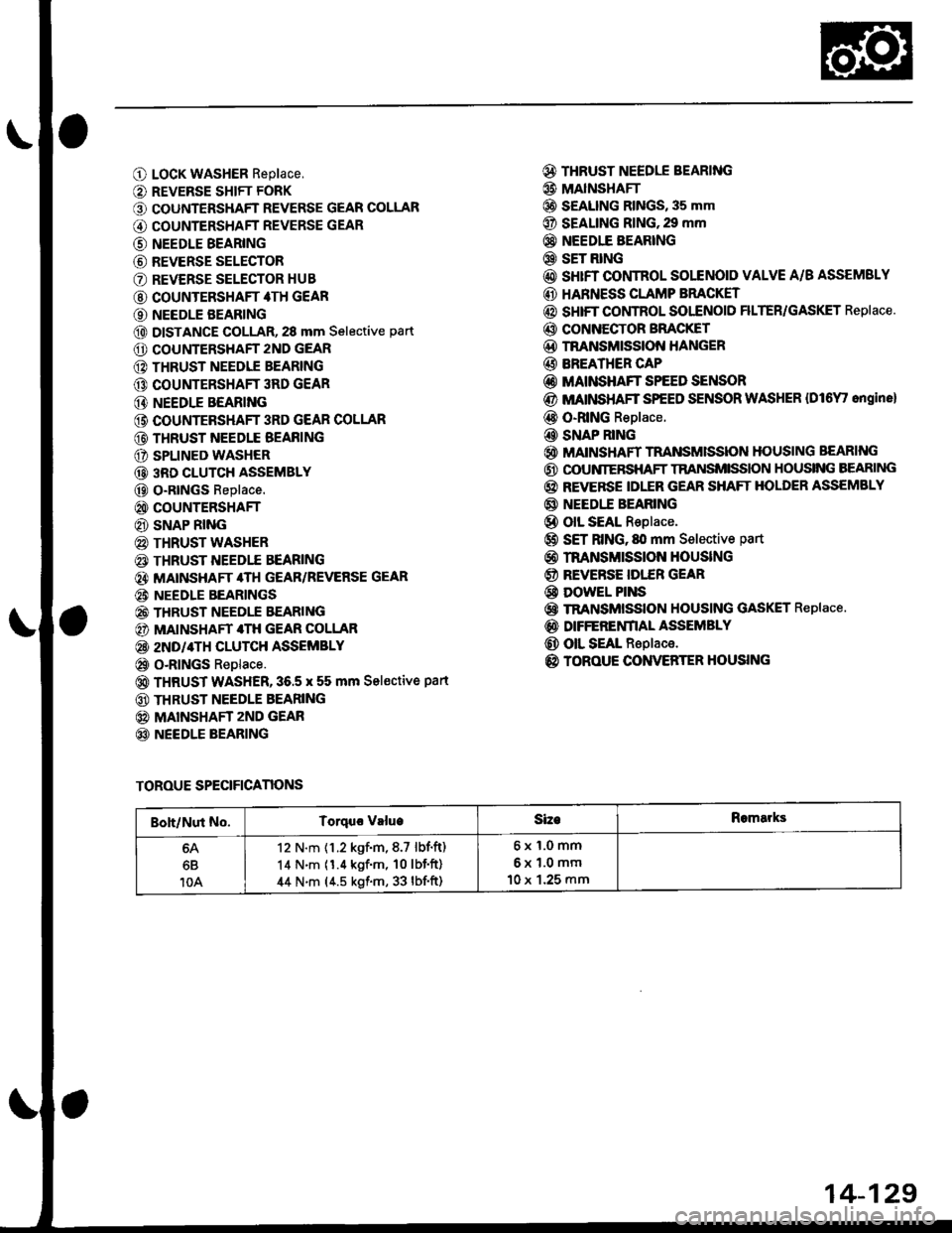
O LocK WASHER Replace,
O REVERSE SHIFT FORK
O COUNTERSHAFT REVERSE GEAR COLLAR
G) COUNTERSHAFT REVERSE GEAR
@ NEEDLE BEARING
@ REVERSE SELECTOR
O REVERSE SELECTOR HUB
@ COUNTERSHAFT 4TH GEAR
O NEEDLE BEARING
@ DISTANCE GOLLAR, 28 mm Selective part
O COUNTERSHAFT 2ND GEAR
@ THRUST NEEDIE BEARING
@ COUNTERSHAFT 3RD GEAR
@ NEEDLE BEARING
@ COUNTEBSHAFT 3RD GEAR COLLAR
@ THRUST NEEDLE BEAFING
O SPLINED WASHER
@ 3RD CLUTCH ASSEMBLY
@ O-RtNGs Replace.
@ COUNTERSHAFT
@ SNAP RING
@ THRUST WASHER
€) THRUST NEEDTE BEARING
@} MATNSHAFT 4TH GEAR/REVERSE GEAR
@i NEEDLE BEARINGS
@ THRUST NEEDLE EEARING
@) MAINSHAFT 4TH GEAR COLLAR
@ 2ND/4TH CLUTCH ASSEMBLY
@ o-RlNGs Replace.
@ THRUST WASHER,36.5 x 55 mm Sel€ctive part
@ THRUST NEEDLE BEARING
@ MAINSHAFT zND GEAR
@ NEEDLE BEARING
@ THRUST NEEDLE BEARING
@ MAINSHAFI
@ S€ALING RINGS, 35 mm
@ SEALING RING,29 mm
@} NEEDIE BEARING
@ SET RING
@ sHrFT CONTROL SOLENOID VALVE A/B ASSEMSLY
@ HARNESS CLAMP BRACKET
@ SHIFT COI,ITROL SOI"ENOID FILTER/GASKET Replace.
@ CONNECTOR BFACKET
@D TNANSMISSION HANGER
@ BREATHER CAP
@ MAINSHAFT SPEED SENSOR
@ MATNSHAFT SPEED SENSOR WASHER {Dl6Y' ongine}
@ O-RING Replace.
@ SNAP RING
@ MAINSHAFT TRANSMISSION HOUSING BEARING
@ OOUNIERSHAFT TRANSMISSION HOUSING BEARING
@ REVERSE IDLER GEAR SHAFT HOLDER ASSEMBLY
@ NEEDI.E BEARING
@ olL SEAL Replace.
@ SET RING, fll mm Selective part
@ rnANsMrssloN HouslNG
@ REVERSE IDI."ER GEAR
@ DowEL PINS
@ TRANSMISSION HOUSING GASKET Replace.
@ DIFFERENfIAL ASSEMBLY
@ OIL SEAL Replace.
@ TOROUE CONVERTER HOUSING
TOROUE SPECIFICANONS
Boh/Nut No.Torquo valueSizeRomarks
6B
10A
12 N.m {1.2 kgf.m,8.7 lbf.ft)
14 N.m (1.4 kgf'm, 10lbf'ft)
44 N.m (4.5 kgf.m, 33 lbf'ft)
6x1.0mm
6x1.0mm
10 x 1.25 mm
14-129
Page 894 of 2189
Description
Hydraulic Flow (cont'd)
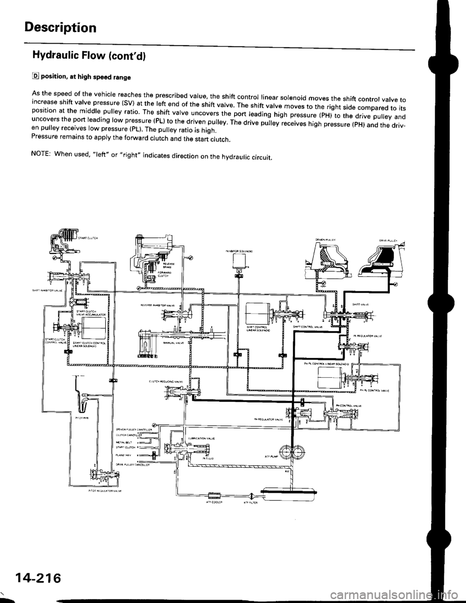
@ position, at high spe6d range
As the speed of the vehicle reaches the prescribed value, the shift control linear sol€noid moves the shift contror vatve toincrease shift valve pressure (SV) at the left end of the shift valve. ttre srrit vatve moves to the right side compared to itsposition at the middle pulley ratio. The shift valve uncovers the port leading high pressure (pxito ttre d.ve puley anduncovers the port leading low pressure (PL) to the driven pulley. The drive pu|ey receives high pressure (pH) and the driv-en pulley receives low pressure (pL). The pulley ratio is high.Pressure remains to apply the forward clutch and the start clutch,
NOTE: When used, "left,, or,,right" indicates direction on the hydraulic circuit.
L
14-216
Page 986 of 2189
![HONDA CIVIC 1998 6.G Workshop Manual O ATF DIPSTICK
O o-RING Replace.
. SOLENOID HARNESS CONNECTOR
@ LOWER VALVE BODY ASSEMBLY
O DOWEL PIN
O LINE BOLT
.i ATTf COOUR IruIET LINE B8ACKET BOLT
€] lrr cooua truler LINE ASSEMBLY
O SEALING HONDA CIVIC 1998 6.G Workshop Manual O ATF DIPSTICK
O o-RING Replace.
. SOLENOID HARNESS CONNECTOR
@ LOWER VALVE BODY ASSEMBLY
O DOWEL PIN
O LINE BOLT
.i ATTf COOUR IruIET LINE B8ACKET BOLT
€] lrr cooua truler LINE ASSEMBLY
O SEALING](/manual-img/13/6068/w960_6068-985.png)
O ATF DIPSTICK
O o-RING Replace.
.' SOLENOID HARNESS CONNECTOR
@ LOWER VALVE BODY ASSEMBLY
O DOWEL PIN
O LINE BOLT
.i ATTf COOUR IruIET LINE B8ACKET BOLT
€] lrr cooua truler LINE ASSEMBLY
O SEALING WASHER RePIACE'
G, ATF COOLER OUTLET PIPE
6) o-RING Replace.
@ ATF FILTER
fO o-RING Replace.
@ ATF PAN(3 DOWEL PIN(D O-RING Replace.
E) ATF STRAINER
@ ATF MAGNET(9 ATF PAN GASKET RePIACE'
O ATF MAGNET
€t oRAIN PLUG
@ SEALING wAStlER Replace.
TOROUE SPECIFICATIONS
Bolt/Nut No.Torque ValueSizeRemarks
8F
12J
18D
12 N.m {1.2 kgf m, 8.7 lbf'ft}
26 N.m (2.7 kgim,20 lbf'ft)
28 N.m (2.9 kgf'm,21 lbf'ft)
49 N.m (5.0 kgf'm, 36 lbf'ft)
6x1.0mm
8 x 1.25 mm
12 x 1.25 mm
18 x 1.5 mm
Line bolt
Drain plug
14-309
Page 1076 of 2189
System Description
Steering Gearbox
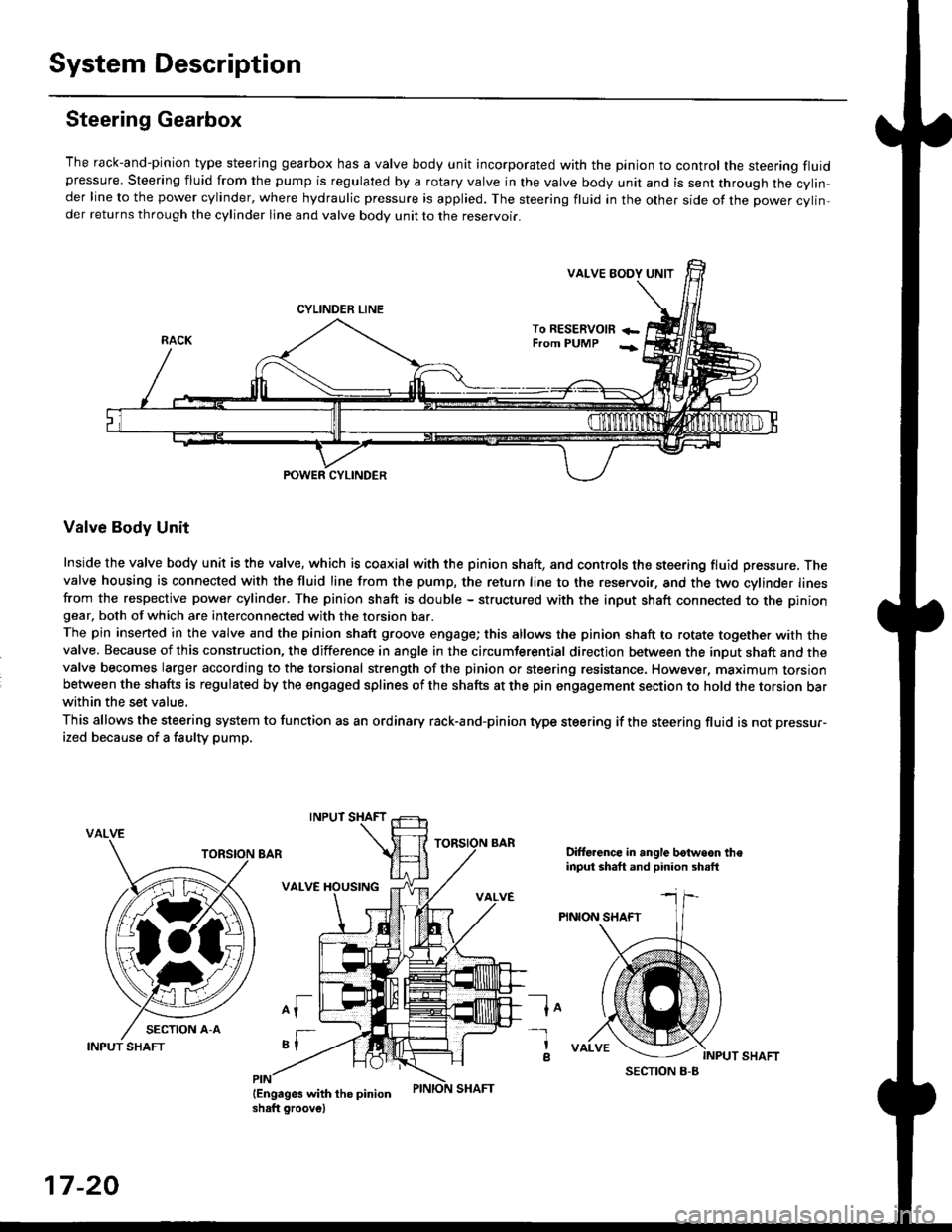
The rack-and-pinion type steering gearbox has a valve body unit incorporated with the pinion to control the steering fluidpressure. Steering fluid from the pump is regulated by a rotary valve in the valve body unit and is sent through the cylin,der line to the power cylinder, where hydraulic pressure is applied. The steering fluid in the other side of the power cylin,der returns through the cylinder line and valve body unit to the reservoii.
VALVE EODY UNIT
CYLINDER LINE
To RESERVOm +-From PUMP -;
POWER CYLINDER
Valve Body Unit
Inside the valve body unit is the valve, which is coaxial with the pinion shaft, and controls the steering fluid pressure. Thevalve housing is connected with the fluid line from the pump, the return line to the reservoir, and the two cylinder linesfrom the respective power cylinder. The pinion shaft is double - structured with the input shaft connected to the piniongear, both of which are interconnected with the torsion bar.
The pin inserted in the valve and the pinion shaft groove engage; this allows the pinion shaft to rotate together with thevalve. Because of this construction, the difference in angle in the circumferential direction between the input shaft and thevalve becomes larger according to the torsional strength of the pinion or steering resistance. However, maximum torsionbetween the shafts is regulated by the engaged splines of the shafts at the pin engagement section to hold the torsion barwithin the set value,
This allows the steering system to function as an ordinary rack-and-pinion type steering if the steering fluid is not pressur-
ized because of a faulty pump,
VALVE
Difforence in angle botwoon theinput shaft and pinion shsft
PINION SHAFT
lo
INPUT SHAFT
-l
a
17-20
INPUT SHAFT
Page 1088 of 2189
Inspection and Adjustment
Pump Belt
NOTE: When using a new belt, first adjust the deflection
or tension to the values for the new belt, then readjust
the deflection or tension to the values for the used beltafter running engine for five minutes.
Inspection
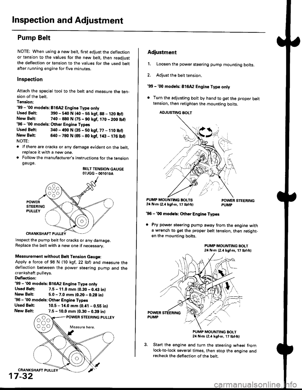
Attach the special tool to the belt and measure the ten-sion of the belt.
Tension:'99 -'00 mod€ls: B1642 Engin. Type onlyUsed Bsh: 390 - 540 N lao - 55 kgt.88 - 120 tbf)New Belt:740 - 880 N {75 - 90 kgf, 170 - 200 tbt}'96 - '00 models: Other Engine Types
Used Beh: 340 - 490 N (35 - 50 kgf, 77 - ilO tbflNew Belt:640 - 780 N 165 - 80 ksf, 1& - 176 tbf)NOTE:
. lf there are cracks or any damage evident on the belt,reDlace it with a new one.. Follow the manufacturer's instructions for the tensiongauge.
BELT TENSION GAUGE07JGG _ 001010A
Inspect the pump belt for cracks or any damage.Replace the belt with a new one if necessary.
Measuremont without Beh Tension Gauga:
Apply a force of 98 N (10 kgt,22 lbfl and measure thedeflection between the power steering pump and thecrankshaft pulleys.
Dsflectior:'99 -'00 model3: 816A2 Engine Typ€ ontyUsed Beh: 7.5 - 11.0 mm t0.30 - 0.43 inlNew Beh:5.0 - 7.0 mm (0.20 - 0.28 in)'96 - '00 models: Othor Engine Typos
Used Behi 10.5 - 14.0 mm (0.ial - 0.59 inlNow Beh:7.5 - 10.0 mm (0.30 - 0.39 inl
POWER STEERING PULUY
CRANKSHAFT PULLEY
17-32
Adiustment
1. Loosen the power steering pump mounting bolts.
2. Adjust the belt tension.
'99 - '00 mod€ls: 816A2 Engin€ Typo only
. Turn the adjusting bolt by hand to get the proper belttension, then retighten the mounting bolts,
ADJUSNNG BOLT
PUMP MOUNNNG BOLTS24 N.m (2.4 kgf'm, 17 tbtftlPOWER STEERINGPUMP
'96 -'00 modek: Othcr Engins Typos
. Pry power steering pump away from the engine witha wrench to get the proper belt tension, then retight-en the mounting bolts.
PUMP MOUNTING BOLT24 N.m (2,4 kgf.m, 17 lbl.ftl
PUMP MOUNTING BOLT24 N.m {2.a kgt m, 17 tbtftl
Start the engine and turn the steering wheel fromlock-to-lock several times, then stop the engine andrecheck the deflection of the belt,
Page 1140 of 2189
Front Suspension
L
Lower Ball Joint Replacement
Remove the knuckle (see page 18-11).
Remove the boot by prying the set ring off.
Check the boot for deterioration and damage.
replace if necessary.
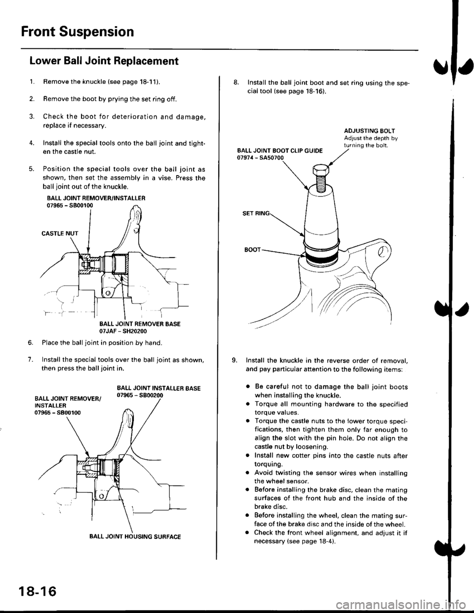
Install the special tools onto the ball joint and tight-
en the casfle nut.
Position the special tools over
shown. then set the assembly in
ball joint out of the knuckle,
BALL JOINT REMOVER/INSTALLER07965 - SB00r00
CASTLE NUT
the ball joint as
a vise. Press the
lf
7.
BALL JOINT REMOVER BASE07JAF - SH20200
Place the ball joint in position by hand.
Install the special tools over the ball joint as shown,
then press the ball joint in.
BALL JOINT INSTALLEB BASE07965 - 5800200
BALL JOINT HOUSING SURFACE
18-16
8. Install the ball joint boot and set ring using the spe-
cial tool (see page 18-16).
ADJUSTING BOLTAdjust rhe depth byturning the bolt.
Install the knuckle in the reverse order of removal,
and pay particular attention to the following items:
. Be careful not to damage the ball joint boots
when installing the knuckle,
. Torque all mounting hardware to the specified
torque values.
. Torque the castle nuts to the lower torque speci-
fications. then tighten them only far enough to
align the slot with the pin hole. Do not align the
castle nut by loosening.
. Install new cotter pins into the castle nuts after
torquang.
. Avoid twisting the sensor wires when installing
the wheel sensor.
. Before installing the brake disc. clean the mating
surfaces of the front hub and the inside of the
brake disc.
. Before installing the wheel, clean the mating sur-
face of the brake disc and the inside of the wheel.. Check the front wheel alignment, and adjust it if
necessary {see page 18-4).