Page 581 of 2189

\
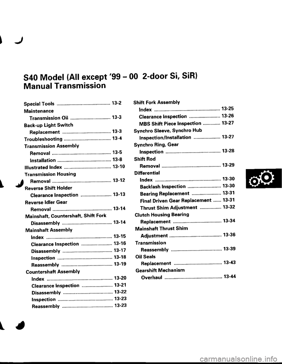
S40 Model (All except'99 - 00 2-door Si' SiR)
Manual Transmission
Special Tools ..'.......... 13-2
Maintenance
Transmission Oil .............................. 13-3
Back-up Light Switch
Replacement ......... 13-3
Troubleshooting '....... 13-4
Transmission AssemblY
Removal ................. 13-5
lnstallation ............. 13-8
lllustrated Index ...............'........."........ 13-10
Transmission Housing
I Removaf .."""""""' 13-12
J R"rr"r"" Shift Holder
Clearance lnspection ....................... 13-13
Reverse ldler Gear
Removal ....'.........." 13-14
Mainshaft, Countershaft, Shift Fork
Disassembly ......'... 13-14
Mainshaft AcsemblY
Index ............... ....... 13-15
Clearance Inspection ..'.................... 13-16
Disassembly .......... 13-17
Inspection ....'......... 13-18
Reassembly ........... 13-19
Countershaft AssemblY
lndex ................ ...... 13-20
Clearance lnspection ."..........'......." 13-21
Disassembly ..."""' 13-22
Inspection .............. 13-23
Reassembly ..'.""... 13-23
Shift Fork AssemblY
lndex ............... ."'... 13-25
Clearance lnspection ."......."........'.. 13'26
MBS Shift Piece Inspection ....-.....'.. 13'27
Synchro Sleeve, Synchro Hub
f nspection/lnstallation .......'...... ".... 13'27
Synchro Ring, Gear
Inspection '....'..".... 13'28
Shift Rod
Removal .'......".""" 13'29
Differential
lndex ......."'...... .'."' 13-30
Backlash Inspection ..........."......."... 13-30
Bearing Beplacement'.............'.".... 13'31
Final Driven Gear Replacement '..... 13-31
Thrust Shim Adiustment ..."........... 13-32
Clutch Housing Bearing
Replacement .......'. 13-34
Mainshaft Thrust Shim
Adiustment '....'..".. 13-36
Transmission
Reassembly ........... 13-39
Oil Seals
Replacement ......... 13-43
Gearshift Mechanism
Overhaul ................ 13-44
\
Page 582 of 2189
Special Tools
Ref. No. I Tool NumbetDescription(Xy I Page Reference
o
@
o.@
!'5,
@
o
@6
@
@
@(3
OTGAJ PG2O11O
OTGAJ PG2012O
07GAJ - PG20130
07736 - A010004
07746 - 0010300
07746 - 0010400
07746 - 0030100
07746 - 0030300
07746 - 0030400
07749 - 0010000
07JAD - PH80101
07JAD - PH80200
07947 - 6110501 or
07947 - 6110500
Mainshaft Holder
Co lla r
Mainshaft Base
Adjustable Bearing Puller, 25 - 40 mm
Attachment. 42 x 47 mm
Attachment,52 x 55 mm
Driver, 40 mm LD.
Attachment, 30 mm I.D.
Attachment, 3S mm LD.
Driver
Driver Attachment
Pilot. 26 x 30 mm
Seal Driver Attachment
1 13-38
1 13-37
1 I 13-37
1 13-34,35
1 13-34.35
1 13-34,35
1 | 13-19,24
31,32
1 13-19,24
1 13-19,24
r I t3-34,35, 43
1 13-43
1 13,43
1 I 13-43
* Must be used with commercially-available 3/8"-j6 Slide Hammer.
oaaal
\91o
aif!
o
ly tr
IvI
Page 588 of 2189

Transmission Assembly
Removal(cont'd)
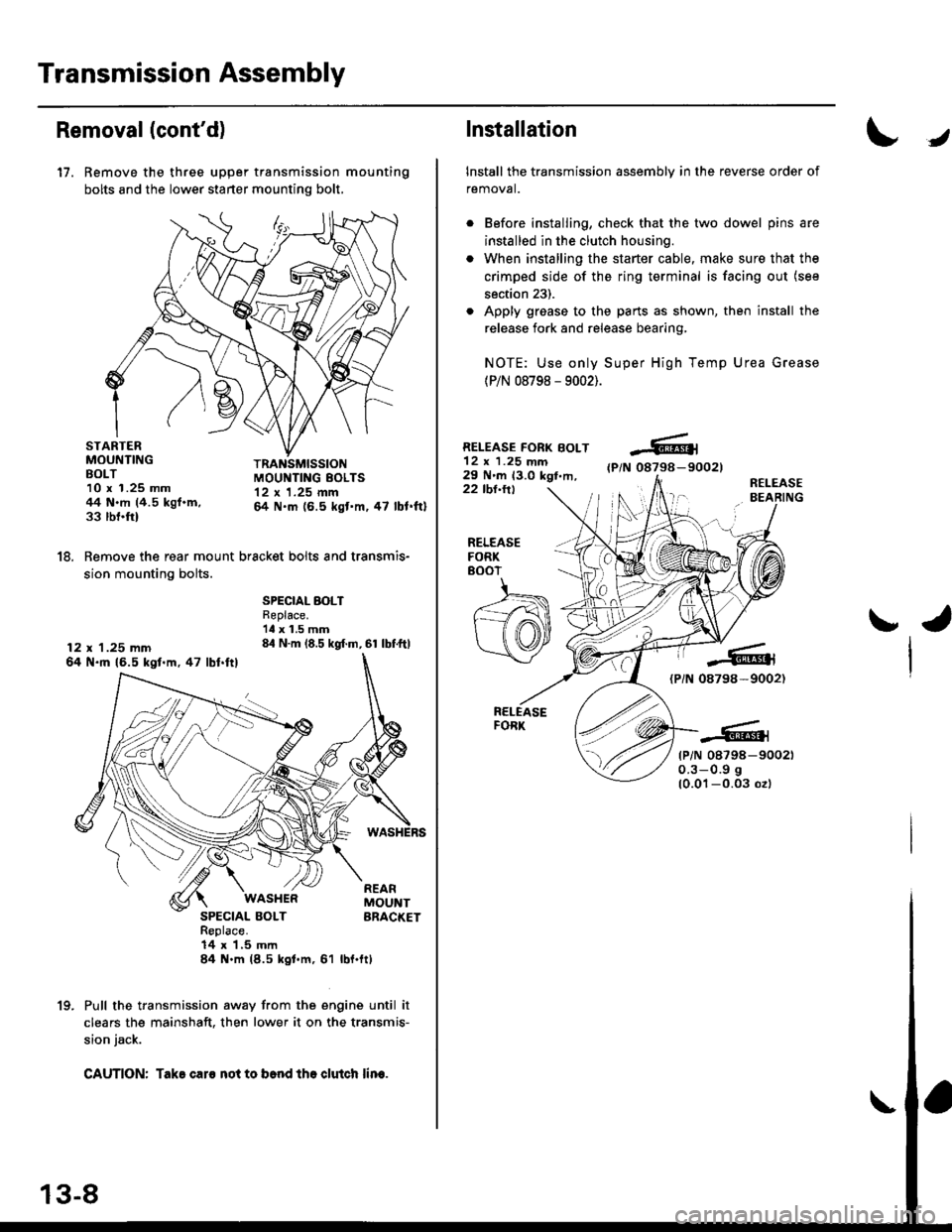
17. Remove the three upper transmission mounting
bolts and the lower starter mounting bolt,
STARTERMOUNTINGBOLT10 x 1.25 mm44 N.m (4.5 kgf.m,33 rbnftl
TRANSMISSIONMOUI{TING EOLTS12 x 1.25 mm& N.m (6.5 kgt'm,47 lbl.ftl
18. Remove the rear mount bracket bolts and transmis-
sion mounting bolts.
12 x 1.25 mm64 N.ft 16.5 kgl.m,47 lbl.ftl
SPECIAL BOLTReplace.'ll x 1.5 mm84 N.m (8.5 kgf.m, 61 lbf.ftl
SPECIAL BOLTReplace.14 x 1,5 mln84 N.m (8.5 kgl.m, 61
WASI{ERREARMOUNTBRACKET
rbl.ftt
Pull the transmission away from the engine until it
clears the mainshaft. then lower it on the transmis-
sion jack.
CAUTION: Take caro not to b6nd tho clutch lin€.
1(|
Installation
Install the transmission assembly in the reverse order of
removal.
Before installing, check that the two dowel pins are
installed in the clutch housing.
When installing the starter cable, make sure that the
crimped side of the ring terminal is facing out (see
section 23).
Apply grease to the parts as shown, then install the
release fork and release bearing,
NOTE: Use only Super High Temp Urea Grease
(P/N 08798 - 9002).
RELEASE FORK BOLT12 x 1.25 mm29 N'm 13.0 kgt,m,(P/N 08798-90021
22 tbl.ttlR€LEASEBEARING
J
RELEASEFORK8()07
ra
{PiN 08798-9002)
tP/N 08798-900210.3-0.9 g
10.01-0.03 ozl
Page 591 of 2189

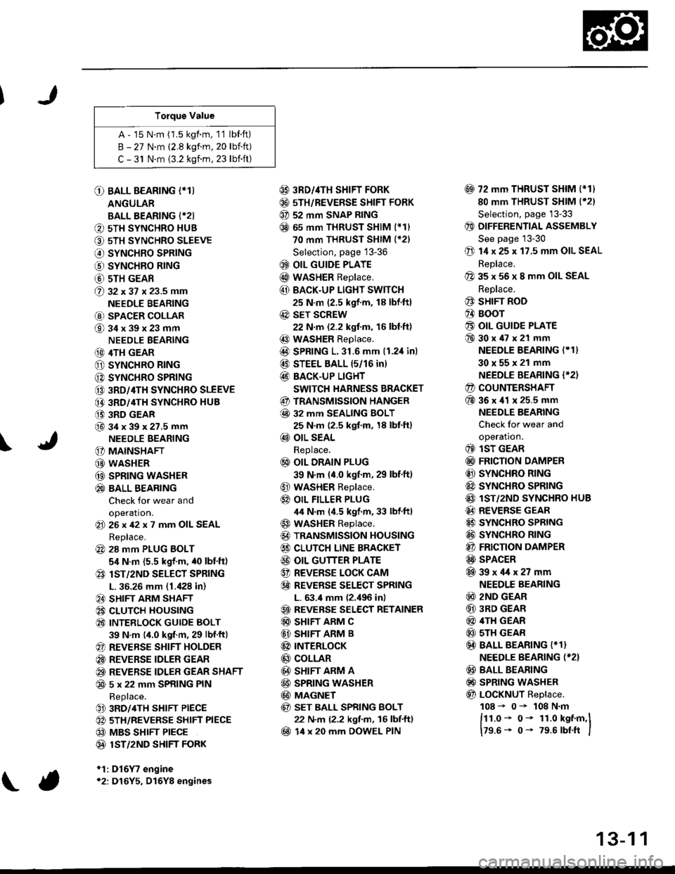
Torque Value
A - 15 N.m (1.5 kgf.m, 1'1 lbf.ft)
B - 27 N.m (2.8 kgf.m. 20 lbift)
C - 31 N.m {3.2 kgnm, 23 lbift)
\
O BALL BEARING (*T)
ANGULAR
BALL BEARING {*2I
O 5TH SYNCHRO HUB
O 5TH SYNCHRO SLEEVE
€) SYNCHRO SPRING
o SYNCHRO B|NG
@ 5TH GEAR
@ gz xgt x 23.5 mm
NEEDLE BEARING
@ SPACER COLLAR
@34x39x23mm
NEEDLE BEARING
(D 4TH GEAR
O SYNCHRO RING
C) SYNCHRO SPRING
CO 3RD/4TH SYNCHRO SLEEVE
@ 3RD/4TH SYNCHRO HUB
(} 3RD GEAR
@34x39x27.5mmNEEDLE BEARING
G) MAINSHAFT
G) WASHER
@ SPRING WASHER
@ BALL BEARING
Check for wear and
operation.(E 26x42x7 mm OIL SEAL
Replace.
@ 28 mm PLUG BOLT
5,1 N.m {5.5 kgf'm, /t0 lbt'ft)
@ lsT/zND SELECT SPRING
L. 36.26 mm (1./P8 in)
@ SHIFT ARM SHAFT
@ CLUTCH HOUSING
@ INTEELOCK GUIDE BOLT
39 N.m (4.0 kgf.m, 29 lbf.ftl
@ REVERSE SHIFT HOLDER
@ REVERSE IDLER GEAR
@ REVERSE IDLER GEAR SHAFT
@ 5 x 22 mm SPRING PIN
Replace.
@ 3RD/4TH SHIFT PIECE
@ 5TH/REVERSE SHIFT PIECE
@ MBS SHIFT PIECE
@ 1ST/2ND SHIFI FORK
*1:D16Y7 engine*2: D16Y5, D16Y8 engines
@ 3RD//|TH SHIFT FORK
@ 5TH/REVERSE SHIFT FORK
@ 52 mm SNAP RING
@ 65 mm THRUST SHIM (*11
70 mm THRUST SHIM (*21
Selection, page 13-36
@ OIL GUIDE PLATE
@ wASHER Replace.
@ BACK.UP LIGHT SWITCH
25 N.m (2.5 kgf'm, 18 lbf'ft)
@ sET SCREW
22 N.m {2.2 kgf.m, 16 lbl.ft}
@ WASHER Replace.
@D SPRING 1.31.6 mm (1.2,1inl
@ STEEL BALL 15/16 in)
@ BACK-UP LIGHT
SWITCH HARNESS BRACKET
@ TRANSMISSION HANGER
@ 32 MM SEALING BOLT
25 N.m (2.5 kgf.m, 18 lbt'ft)
@ OIL SEAL
Replace.
@ OIL DRAIN PLUG
39 N.m (4.0 kgf.m, 29 lbf.ft)
@ WASHER Replace.
@} OIL FILLER PLUG
44 N.m (4.5 kgf.m, 33 lbf'ftl
@ WASHER Replace.
@) TRANSMISSION HOUSING
€) CLUTCH LINE BRACKET
@ OIL GUTTER PLATE
@ REVERSE LOCK CAM
@ REVEBSE SELECT SPRING
L. 63.4 mm {2.,196 in)
@ REVERSE SELECT RETAINER
@ SHIFT ARM C
@ SHIFT ARM B
@ INTERLoCK
@ COLLAR
@ SHIFT ARM A
@ SPRING WASHER
@ MAGNET
@ sET BALL SPRING BOLT
22 N.m (2.2 kgf.m, 16 lbf.ftl
@ 14 x 20 mm DOWEL PIN
@ 72 mm THRUST SHIM l*11
80 mm THRUST SHIM (*21
Selection, page '13-33
@ DIFFERENTIAL ASSEMBLY
See page 13-30
@ 14 x 25 x 17.5 mm OIL SEAL
Replace.
@ 35 x 56 x 8 mm OIL SEAL
Replace.
@ SHIFT ROD
@ BOOr
@ OIL GUIDE PLATE
@30x47x21 mm
NEEDLE BEARING (* 1}
30x55x21 mm
NEEDLE BEARING {'2)
@ COUNTERSHAFT
@36x41 x 25.5 mm
NEEDLE BEARING
Check for wear and
operatron.
@ lsT GEAR
@ FRICTION DAMPER
@ SYNCHRO RING
@ SYNCHRO SPRTNG
@ lST/2ND SYNCHRO HUB
@ REVERSE GEAR
@ SYNCHRO SPRING
@ SYNCHRO RING
@ FRICTION DAMPER
@ SPACER
@39x4lx27mm
NEEDLE BEARING
@ 2ND GEAR
@ 3RD GEAR
@ 4TH GEAR
@ sTH GEAR
@) BALL BEARING {* 1}
NEEDLE BEARING (*2}
@ BALL BEARING
@) SPRING WASHER
@ LoCKNUT Replace.
108 - 0- 108 N.m
ftt.o* o- 1r.o kst.m,l
179.6- 0- 79.6 rbtft I
13-1 1
Page 595 of 2189

Mainshaft Assembly
I
lndex
Note the following during reassembly:
. The 3rd/4th and sth svnchro hubs are installed with a press
. Install the angular ball bearing with the thin-edge outer race facing the sth synchro hub
. Install the ball bearing with the ball cage facing up
prior to reassembling, clean all the parts in solvent, dry them and apply lubricant to all contact surfaces the 3rd/4th
and sth svnchro hubs.
Ballcage faces uP.
Thin edge of outerrace laces down.
3RD/4TH SYNCHRO SLEEVE
page 13'27
SYNCHRO SPRINGSYNCHRO RINGInspection,page 13-28
BALL BEARING {*1)ANGULAR BALL BEARING ('2)
Check for wear and operataon.Note the direction ot installation
5TH SYNCHROSLEEVElnspection, page 13-27
SYNCHRO HUB
SYNCHRO RINGInspection, pase 13 28
sTH GEARInspection, page 13-17
3RD GEARlnspection, page 1 3-1 6
34 x 39 x 27.5 mmNEEDLE BEARINGCheck for wearano opetaflon,
MAINSHAFTInspection, page 13-18
CHAMFEB
32 x 37 x 23.5 mmNEEDLE BEARINGCheck for wear andoperation.SPACER COLLABInspection, page 1316
34x39x23mmNEEDLE EEARINGCheck for wearand operation,
4TH GEARrnspeclron,
*1: D16Y7 engine*2: D16Y5, D16Y8 engines
page 13'16RINGInspectaon, page 13 28
SPRING
13-15
Page 597 of 2189

T
6. Measure the clearance between the spacer collar
and sth gear.
Standard: 0.06 - 0.19 mm 10.002 - 0.007 inl
Service Limit: 0.31 mm (0.012 inl
4TH GEAR
DIALINDICATOR
I
-<=q,
7.
5TH GEAR
lf the clearance is more than the service limit, mea-
sure distance @ on the spacer coilar
Standard: 23.53 - 23.56 mm
10.926 - 0.928 in)
Sowice Limit 23.51 mm {0.926 in}
SPACERCOLLAR
sTH GEARSIDE
lf distance @ is less than the service limit, replace
the spacer collar with a new one,
lf distance @ is within the service limit, measure
thickness of 5th gear.
Siandatd:28.1:2 - 28.17 mm
11.119 - 1.121 in)
Servica Limit: 28.35 mm (1.116 inl
sTH GEAR
lf the thickness of 5th gear is less than the ser-
vice limit, replace sth Oear with a new one.
lf the thickness of sth gear is within the service
limit, replace the 5th synchro hub with a new
one.
Disassembly
1. Remove the ball bearing using a bearing puller as
shown.
BEARING PULLER(Commercially
availablel
CAUTION: Remov€ ths synchro hubs using a press
and steel blocks as shown. Us€ of a iaw-type pullel
can caus€ damage lo the gear teeih.
Support 4th gear on steel blocks. and press the
mainshaft out of the sth svnchro hub as shown.
{cont'd)
13-17
Page 598 of 2189
Mainshaft Assembly
Disassembly (cont'd)
3. Support the 3rd gear on steel blocks, and press the
mainshaft out of the 3rd/4th synchro hub as shown.
13-18
Inspection
'1. Inspect the gear surface and bearing surface for
wear and damage. then measure the mainshaft atpoints A, B, C, and D.
Siandard: A: 21.987 - 22.000 mm
10.8656 - 0.8661 inl
B: 26.980 - 26.993 mm
11.0622 - 1.0627 inl
C: 33.98,1- 34.000 mm(1.3380 - 1.3385 in)
D: 25.977 - 25.990 mm
|.1.0227 - 1.0232 inl
Service Limit: A: 21.930 mm 10.8634 inl
B: 26.930 mm {1.0602 in}
C: 33.930 mm (1.3358 in)
D: 25.920 mm (1.0205 in)
Check for wear and damage
lf any part of the mainshaft is less than the service
limit, replace it with a new one.
2. Inspect for runout.
Standardi 0.02 mm (o.(Xtl in) max.
S€rvice Limii: 0.05 mm (0.002 in)
NOTE: Support the mainshaft at both ends as
snown.
lf the runout is more than the service lirnit, reolace
the mainshaft with a new one.
Y
Page 614 of 2189
Clutch Housing Bearing
Replacement
Mainshaft
1. Remove the ball
shown.
bearing using the special tool as
3i8 " -16 SLIDE HAMMER(Commercially available)
ADJUSTAELE BEARINGPULLER, 25-40 mm07736-AO10004
2, Remove the oil seal from the clutch housing,
CLUTCH
Replace.
13-34
l.
3, Drive the new oil seal into the clutch housing usingthe specialtools as shown.
ATTACI{MENT, 42 x 47 mm07746 -0010300
CLUTCHHOUSING
Drive the ball bearing into the clutch housing usingthe special tools as shown.
ATTACHMENT, 52 x 55 mm DRIVER07746 001040007749-0010000
t./
07749 -0010000