1998 HONDA CIVIC MAIN WIRE
[x] Cancel search: MAIN WIREPage 507 of 2189

Fuel Supply System
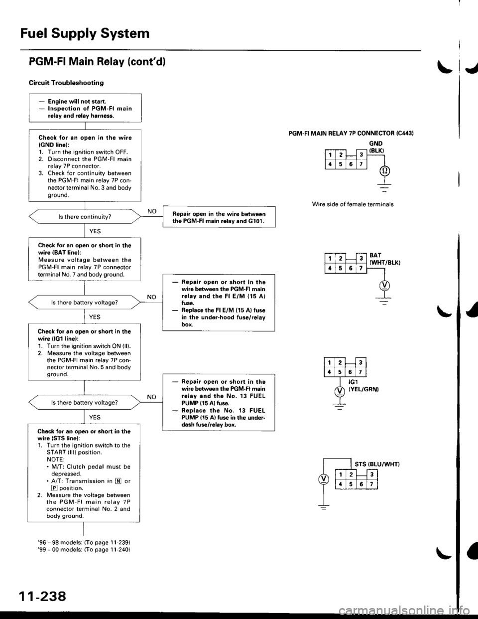
PGM-FI Main Relay (cont'dl
Circuit Troubleshootin g
PGM.FI MAIN RELAY 7P CONNECTOR {C443)
GND{8LK)
Wire side of female terminals
/BLK}
- Engine will not start.- lnsoection of PGM-FI mainrelay and relay harne$.
Check for an open in the wire{GNO line}:l. Turn the ignition switch OFF.2. Disconnect the PGM-Fl mainrelay 7P connector.3. Check for continuity betweenthe PGM Fl main relay 7P con-nector terminal No.3 and bodyground.
Ropai. open in the wir€ betweenthe PGM-FI main .elav and G101.
Check for an open or short in thewire {BAT lin€}:N4easure voltage between thePGM-FI main relay 7P connectorterminal No. 7 and body ground.- Repair open or sho.t in thewire between the PGM-FI mainrelay and the Fl E/M {15 A}fus€.- Replace the Fl E/M (15 Allu3ein the under-hood fuse/relayoox.
ls lhere battery voltage?
Check tor an open or short in thewire {lGl line):1. Turn the ignition switch ON (ll).
2. Measure the voltage betweenthe PGM-Fl main relay 7P con'nector terminal No. 5 and bodyground.- Repair open or short in thewire betwoen the PGM-FI mainrelav and the No. 13 FUELPUMP (15 A)tuse.- R€place the No. 13 FUELPUMP {15 A} tus€ in the under-d.sh fus€/relay box.
ls there battery voltage?
Ch.ck for an open or short in thewire {STS lino}r1. Turn the ignition switch to theSTART (lll) position.NOTE:. M/T: Clutch pedal must beoepresseo.. A/T: Transmission in E or
E position.2, Measure the voltage betweenthe PGM-Fl main relay 7Pconnector terminal No, 2 andbody ground.
12
[,a567
123BAT
{WHTa56,
'96 98 models: (To page 1l 239)'99 - 00 models: (To page I l-240)
11-238,
Page 508 of 2189

JI
I
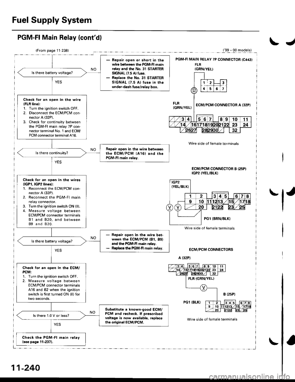
- Repair open or 3hort in the
wire bstw€er the lGM-Fl mainrolsy .nd the No. 31 STARTERSGNAL 17.5 A) tuse.- Reolace the No. 31 STARTER
SIGNAL (7.5 Al fu3o in the
unde.-dash tusg/rolav box.
ls there baftery voltage?
Chock lor !n open in the wit.
lFLn line)l1. Turn the ignition switch OFF
2. Disconnect the ECM/PCM con-
nector A (32P).
3. Check for continuity between
the PGM-FI main relay 7P con-
nectorterminal No. 1 and ECM/
PCM connector terminal A16.
Ropair op6n in th. walo betwoanthe ECM/PCM lA16) and thc
PGM-FI main rolaY.
Ch6ck for an opon in th. wi.e3
llcPl,lGP2linesl:1. Reconnect the ECM/PCN4 con-nector A (32P).
2. Reconnoct the PGM-Fl main
relay connector,3. Turn the ignition switch ON (ll)
4. Measure voltage between
ECM/PCM connector termanals
A11 and A10, and betweenA24 6nd A10.
Repeir opon in th6 wire bet-
ween ttre ECiA /PCM (A11, A24)
and tho PGM-FI msin r.lty.
R€plac. tho FGM-FI main rc|.Y.
Check tor an open in the ECM/
PCM:1. Turn the ignition switch OFF.
2, Measure voltage between
ECM/PCM connector terminalsA16 and A10 when the ignition
switch is lirst turned ON (ll) for
two seconds.
Substituta a known-good ECM/
PCM and rechcck. lf proacribod
voltege is now availablc, r.Placethe originll ECM/PCM.
ls thero 1.0 V or less?
Ch6ck th. PGM-FI m.in lolay(.ee pagc 11-2371.
('96 - 98 models)
t32Pt
Wire side of female terminals
IGP2{YEL/BLKI
FLRIGRN/YELIPGl
3l5 6 7l lslel tl1l
1213'tal5t6't7t8t920221 232a
2527284t
(cont'd)
1 1-239
IBLK)
{GRN/YELI
FLR(GRN/YELI
23
()a6t
ECM/PCM CONNECTOR A
21Il0t1
12r31'al5't61'tti9ml,/x2232a
25212e293ol./
PGl (BLK)
1I
12't/t15t617t8t9zi
25272A4t304l
Page 509 of 2189

Fuel Supply System
- Repair op€n or short in thewir€ betlveen the PGM-FI mainrelay and the No. 31 STARTERSIGNAL 17.5 A) fuse.- RoDlace the No. 31 STARTERSIGNAL {7,5 Al tuse in theunder-dash luse/rolay box.
ls there battery voltage?
Check tor an open in the wire(FLR linel:1. Turn the ignition switch OFF.2. Disconnect the ECM/PCM con-nector A (32P).
3. Check for continuity betweenthe PGM-FI main relay 7P con-nector terminal No. 1 and ECM/PCM connector terminal A16.
Repair open in the wir6 botweenthe ECM/PCM (A161 and rhePGM-FI main relay.
Check for an open in the wires{lGPl, lGP2 line3):1. Reconnect the ECM/PCM con-nector A {32P).2. Reconnect the PGM-Fl mainrelay connector.3. Turn the ignition switch ON (ll).
4. Measure voltage betweenECN4/PCM connector terminals81 and 820, and betweenBg and 820.
- Repair open in the wire bet-ween th. ECM/PCM (81, Bg)snd the PGM-F main rolay.- Roplace th€ PGM-FI main relav.
Chock tor an open in th6 ECM/PCM:1. Turn the ignition switch OFF.2. Measure vo ltage betweenECM/PCM connector terminalsA16 and 82 when the ignitionswitch is first turned ON lll) for
Sub3titute . known-good ECM/PCM and rochock. lf prescribedvohege is now available, replacethe original ECM/PCM.
ls there 1.0 V or less?
Chock the PGM-Fl m.in r6lay{see p.ge 11-2371.
PGM-FI Main Relay (cont'd)
_._(9x . qq -gqerll _
PGM.FI MAIN FELAY 7P CONNECTOR {C4€}FLR
ECM/PCM CONNECTORS
A (32P1
Wire side ot female terminals
Wire side of fem6le terminals
ECM/PCM CONNECTOR B {25PIIGP2 {YEL/BLKI
IGRN/YEL}
IGP2(YEL/BLKI
Wire side of female terminals
11-240
IJ
'l'
Page 748 of 2189

Electrical Troubleshooting ('96 - 98 Modelsl
Troubleshooting Flowchart - Mainshaft Speed Sensor
NOTE: Record all freeze data before you troubleshoot.
Po$ible Cause
. Disconnect€d mainshaft sD€edSensor @nnoctot. Short or open in mainshattsJt€ed s6nsoa wire. Faulty mainshaft lpeed s6nso.
NOTE: Code P0715 (15) on the PCMdoesn't always mean there's an electricalproblem in the mainshaft or countershaftspeed sensor circuit; code P0715 (15)may also indicate a mechanical problemin the transmission.
MAINSHAFT SPEEOSENSOR CONNECTOR
Terminal side of male terminals
PCM CONNECTOR B I25PI
. OBD ll Scan Tool indicates Codem715.. Self-dirgnosi3 E indicatorlight indicstes Code 15.
Check the mainshaft and counter-shaft speed sensor installation.
Are the mainshaft and countershaftspeed sensor installed properly?
Moasure Mainshaft Spoed SgnsolRosistance at the Sensor Con-n€ctor:1. Disconnect the 2P connectorfrom the mainshaft speed sen-sor connector.2. Measure the resistance ot themainshaft speed sensor.
ls the resistance 400 600 O?
Check Mainshaft Sp6ed Sensorfor a Short Circuil:1. Disconnect the B {25P) connec'tor lrom the PCM.2. Check for continuity betweenbody ground and 815 terminaland the 814 terminal individu,
Repai. shon in the wi.os bstwoenthe 815 and 814 te.minals andthe mainshatt .Dood 3ensor.
ls there continuity?
To page 14-71
14-70
Wire side of female terminals
Page 749 of 2189

From page 14-70
Mea3uro Main3haft speed sensor
Resistance:1. Connect the ma;nshaft sPeed
sensol 2P connector,2. [/leasu re the resistancebetween the 815 and 814 ter_minals.
Run the Electical TrouH€.hootingFlowcirrt for cod. P0720 l9l.Check for loose P1CM connoctors.ll n€cesslrY, 3ubstitute a known'good PCM and racheck.
ls the resistance 400 - 600 O?
Check NM wire Continuityl1. Disconnect the 2P connectorfrom the mainshaft speed sen'
sor connector.2. Check for continuity between
the 815 terminal and the No. 1
terminal of the mainshaft
speed sensor connector.
Rgpsi. opon in thc wira bctwg€n
the 815 torminrl and th6.tain_shatt soeod lensoa,
Check NMSG Wire ContinuitYr
Check for continuity between the
814 terminal and the No.2 terminal of the mainshaft sp€ed sensorconnector,
Repair open in the wira botwGonthe 814 terminal and lhe main'shsft spo€d 3en3or.
Check for loo3o PCM connoctoB.ll neca$8ry, subditute a known-good PCM and rgchock.
PCM CONNECTOR B I25PI
Wire side oI female termlnals
MAINSHAFT SPEED SENSOR
CONNECTOR
14-71
Page 773 of 2189

Troubleshooting Flowchart - Mainshaft Speed Sensor
NOTE: Record all freeze data before you troubleshoot.
Possible Causg
. Diaconn€cted mainshaft spoed
sen3or connector'Short or open in mainshaft
sDeed sen3or wile. Faulty main3halt speed sensor
NOTE: Code P0715 (15) on the PCM doesn't
always mean there's an electrrcal problem in
the mainshaft or countershaft speed sensor
circuit; code P0715 {15) may also indicate a
mechanical problem in the transmissjon Any
problem causing irregular countershaft to
mainshalt speed difference can cause thls
code.
lll ,..TT
(ol-i-l
tl
side oI male terminals
MAINSI{AFT SPEEDSENSOR CONNECTOR
Terminal
PCM CONNECTOR D (16P)
NMSG (WHT)
Wire side of female terminals
(cont'd)
14-95
. OBD ll Scan Tool indicates Codem715.. Sell-diagno3is E indicator indi-
cates Code 15.
Check the mainshaft and counter-
shatt speed sensors installation,
and check them for damage.
Are the mainshaft and countershaft
speed sensor installed properly,
and not damaged?
Rsinalall or replace and rocheck.
Mea3u.e Meinshalt SPeod
Sensor Residance al the Sen3or
Connector:1. Disconnect the 2P connectorfrom the mainshaft sPeedsensor.2, Nreasure mainshaft speed sen_sor resistance at the sensorconnector.
ls the resistance 400 - 600 O?
Check Mainshaft Sp.ed Sen3o.
for a Short Circult:1. Disconnect the D (16P) con-nector trom the PCM.2. Check lor continuity betweenbody ground and the D11 ter'minal and D12 terminal indi
vidually.
Bopair 3hort in the wiros b€twe€nthe 011 and D12 termin.ls rndth€ main3hett sp€€d aensoa.ls there continuity?
To page 14 96
Page 774 of 2189
![HONDA CIVIC 1998 6.G Workshop Manual Electrical Troubleshooting (gg - 00 Models)
Troubleshooting Flowchart - Mainshaft Speed Sensor (cont,dl
Wire side of female terminals
PCM CONNECTOR D {16PI
23/)
618
rghrll [e]
NM IREDI
(
I
NMSG {WHTI HONDA CIVIC 1998 6.G Workshop Manual Electrical Troubleshooting (gg - 00 Models)
Troubleshooting Flowchart - Mainshaft Speed Sensor (cont,dl
Wire side of female terminals
PCM CONNECTOR D {16PI
23/)
618
rghrll [e]
NM IREDI
(
I
NMSG {WHTI](/manual-img/13/6068/w960_6068-773.png)
Electrical Troubleshooting ('gg - 00 Models)
Troubleshooting Flowchart - Mainshaft Speed Sensor (cont,dl
Wire side of female terminals
PCM CONNECTOR D {16PI
23/)
618
rghrll [e]
NM IREDI
(
I
NMSG {WHTI
(REDI
MAINSHAFT SPEEDSENSOR OONNECTORRED
Wire side of female terminals
NMSG IWHTI
From page l4-95
Measure Mainshatt SpeedSensor Resistance:1. Connect the mainshaft speedsensor connector.2. Measure the resistance bet-ween the Dl1 and D12 termi-nats.
Run the Electricel Troubl€shootingFlowchart lor cod6 m?m l9).Ch€ck lor loo.o te.minol fit in th6PCM connectors. lf necossary,substitute r known-good PCMend .echeck.
ls the resistance 400 - 600 0?
Check NM Wire Continuity:1. Disconnect the 2P connectorfrom the mainshaft speed sen-sor.2. Check for continuity betweenthe D11 terminal and the No. 2terminal ot the mainshaftspeed sensor connector,
Ropair opon in the wiro lratwoentho Dll tsrminal and tha main-3hatt spe€d sensor.
Check NMSG Wire Continuity:Check for continuity between theDl2 terminal and the No. 1 termi-nal of the mainshaft spoed sen-
Repai. open in the wire betwoenthe D12 terminal and the mein-shaft 3peod sansor.
Check Ior loose terminal fit in thePCM connectors. lf necesaary.substitute a known-good PCMand recheck.
1235
678
t1vNM
o
617 89ll12
Io
t1v
WHT
1
\
14-96
Page 780 of 2189

Electrical Troubleshooting ('99 - 00 Models)
Troubleshooting Flowchart - E Indicator Light Does Not Come On
FCM CONNECTOR B (25P}
LGl {8RN/ALKI{BRN/8LK}
Wire side ol temale terminals
LGl IBNN/BLK} LG2 {BRN/BLK)
i2t5 6q
910t7
LG2
o) (o
The Pll indicator light does notcome on when the ignitionswitch is fi.st turned ON (ll). lltshould come on for about twoseconda.l
Check the Service Check Con-nector:Make sure the special tool (SCS
Service Connector) is not connect-ed to the service check connector?
ls the specialtool {SCS ServiceConnector) is not connected tothe seNice check connector.
Disconnect the special tool fromthe service check connector andr6check.
Check the Dll lndicator LightiShift to d position.
Check for loose terminal fit in thePCM connecto13. It necessary.sub3titute a known-good PCMand recheck.
Does the @ indicator lightcome on?
Check the Ground Circuit:1. Turn the ignition switch OFF.2. Disconnect the B (25P) con-nector from the PCM.3. Check for continuity betweenthe 820 terminal and bodyground, and between the 822terminal and body ground.
Repair open in the wiresbetween the B20 rnd 822 termi-nals and ground (G101), andrep.ir poor ground (G1011.
Measure Power Supply CircuitVoltage:1. Turn the ignition switch ON {ll}.2. Measure the voltage betweenterminals B1 and 822 andbetween terminals Bg and820.
Repair open or short in the wi.obetween th6 81 and/or 89 termi-nals and the PGM-FI main relav,and between th€ PGM-FI mainr€ley rnd the under-hood tus€/relay box.
To page 14''103
14-102