1998 HONDA CIVIC Fuse radio
[x] Cancel search: Fuse radioPage 2024 of 2189
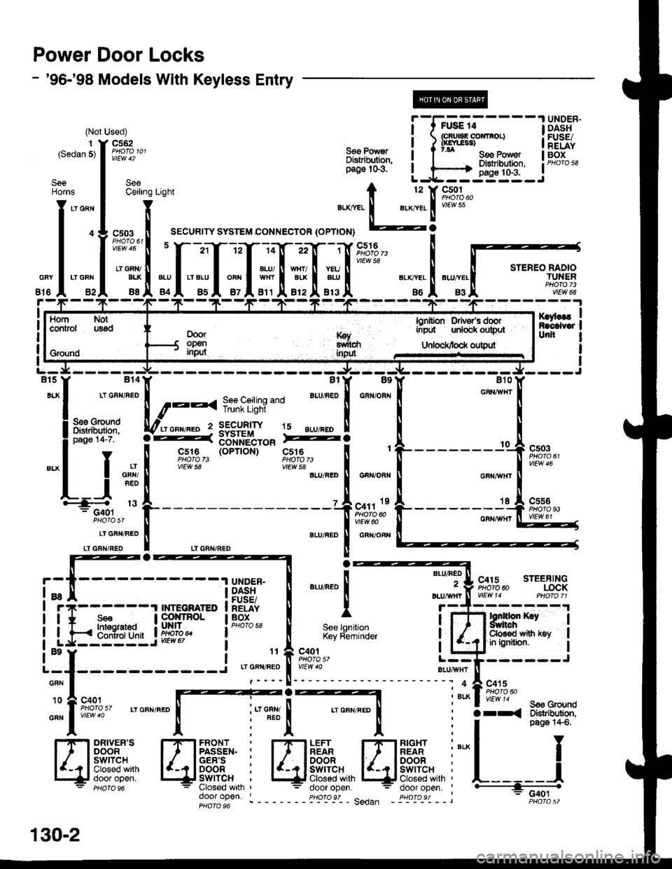
Power Door Locks
- '96-'98 Models With Keyless Entry
(NotUsed)
c562(Ssdan 5)
lOY,laEntcalYatrt oil
SeeCeiling
"*. IPHaTo 611
""#!
__ It
Seenorns
,J:l
ffi
!l*1'*
Rf,Ltr: a ?'* seePower IU6il'
il"d!rui' i.^h::Eii:,_J"'"'ou
t 12 't( 9_s!-1 .
",.*.*,.
1 ".*..1 i#??'o
sYsrEM coNNEcroR (oPTroN) -?
1 UNDER-FUAE 14I t rusE r4: Grul8E COirIFOL)I / 0(Enr38)See Power i ? 7.1 c.. o.Di8tributlon. ! | X;i*:
I DASHI FUSE/I RELAY
STEREO RADIOTUNERPHOTO 73vlEW 68
cs03
css6
;f,;z3,'9,*-
14n 22
BLU/ N WHT/ II YEUWHTI ALK I ALU
B11l'B12l.B13
'I tF;?,'
-xlru
c5l6
86 |' 83
''tl
*, **
t"
[ro**:"[fi*'
""i,
;: I;"il"."'Y' o-ft 3[tnlt$ro" Fi:a
I "* |
F,%',3,, (o"''on)
ir?rt,:*,"." I """,,":
See lgnitionKey Reminder
door ooen. ' pHoro s7 .------- Sa.lan -
f - | csre iofiib$'-" "c,s;rg,_ !
'
| ! "* I
"i3tr9"" 'LU,RED I GnNioR,.
!=4 ,. L----- --,1"n,,'.
-'-l i
i*-i---- ll}gii I
*,*"1
I r7r------'t TNTEGMTED I RELAY I Irrlll,l.I INTECru$ED I RELAY| * s€€ | cotlrRol lBox
LJaBIEIIL i9,Fis," ieHo'osa
BLU/HEO
2
Btu/,|\mr
C415 STEERINGPHOTO 60LOCK
I
I
I
BLUAIIXT
Hffirp;,ruml*-*i E;ffi*,ru
4
ALK
-- ---- J
c415
YtEw 14 sss G,g{rndarr< Olstrlhdion,
RIGHTREARDOORswrTcHClosed withdoor open.
""L___J
G401
130-2
Page 2030 of 2189
Power Door Locks (cont'd)
Keyless Entry Does Not Work In Any
Mode
NOTE: Before beginning, verify that all the
transmitters are programmed to the vehicle.
1 . Does the radio work properly?
Yes - Go to step 9.
No - Go to the neld step.
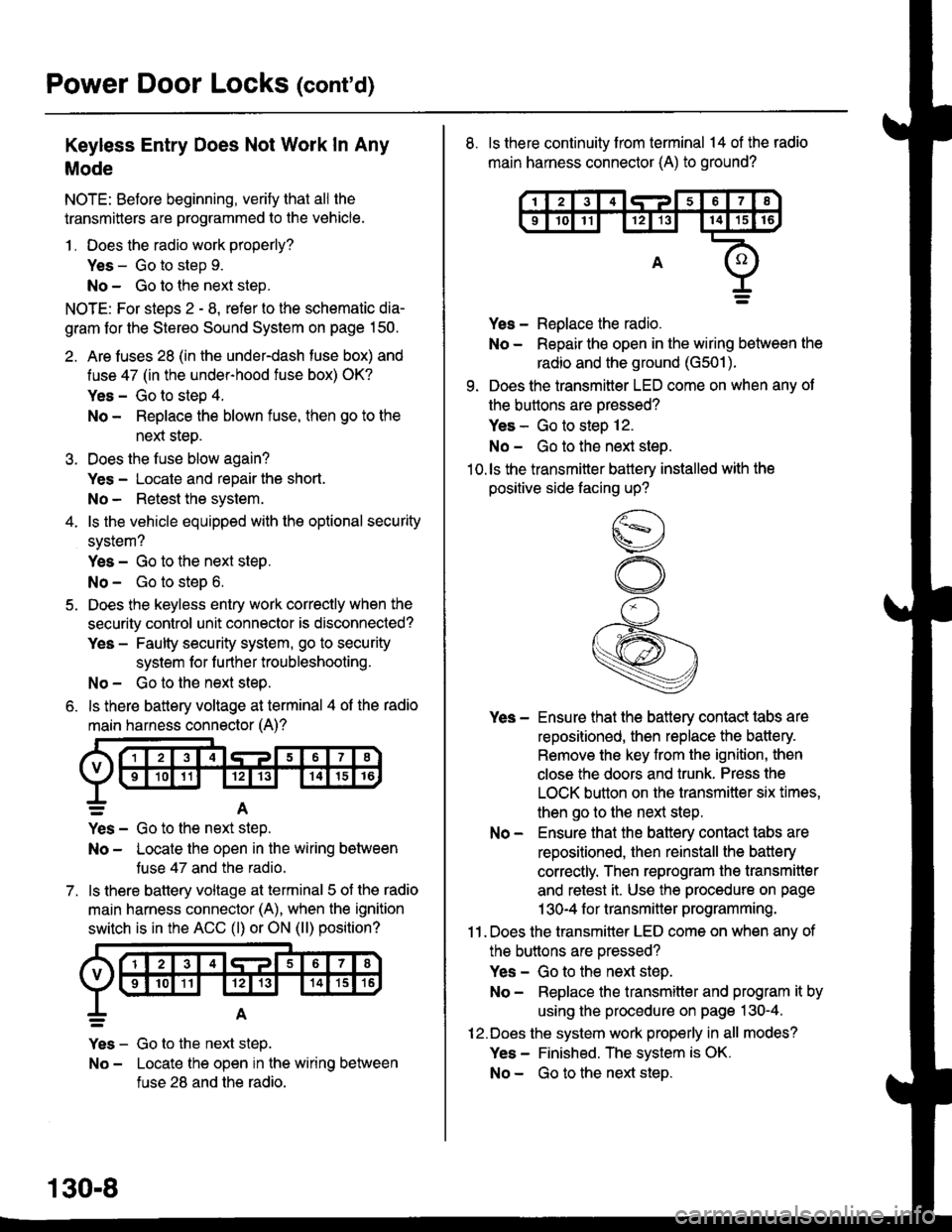
NOTE: For steos 2 - 8. refer to the schematic dia-
gram for the Stereo Sound System on page 150.
2. Are fuses 28 (in the under-dash fuse box) and
fuse 47 (in the under-hood fuse box) OK?
Yes - Go to step 4.
No - Replace the blown fuse, then go to the
nen steo.
3. Does the fuse blow again?
Yes - Locate and repair the short.
No- Retest the system.
4. ls the vehicle equipped with the optional security
system?
Yes - Go to the next steP.
No - Go to steD 6.
5. Does the keyless entry work correctly when the
security control unit connector is disconnected?
Yes - Faulty security system, go to security
system for f urther troubleshooting.
No - Go to the next step.
6. ls there battery voltage at terminal 4 of the radio
main harness connector (A)?
7.
=A
Yes - Go to the nen step.
No - Locate the open in the wiring between
tuse 47 and the radio.
ls there battery voltage at terminal 5 of the radio
main harness connector (A), when the ignition
switch is in the ACC (l) or ON (ll) position?
Yes - Go to the next step.
No - Locate the open in the wiring between
fuse 28 and the radio.
130-8
8. ls there continuity from terminal 14 of the radio
main harness connector (A) to ground?
Yes - Replace the radio.
No - Repair the open in the wiring between the
radio and the ground (G501).
9. Does the transmitter LED come on when any ot
the buttons are oressed?
Yes - Go to steo 12.
No - Go to the next steo.'10.ls the transmitter battery installed with the
positive side facing up?
Yes - Ensure that the battery contact tabs are
repositioned, then replace the battery.
Remove the key from the ignition, then
close the doors and trunk. Press the
LOCK button on the transmitter six times,
then go to the next step.
No - Ensure that the baftery contact tabs are
repositioned, then reinstall the batlery
correctly. Then reprogram the transmitter
and retest it. Use the procedure on page
1 30-4 f or transmitter programming.
11 . Does the transmitter LED come on when any of
the buttons are oressed?
Yes - Go to the next step.
No - Replace the transmitter and program it by
using the procedure on page 130-4.
12.Does the system work properly in all modes?
Yes - Finished. The system is OK.
No - Go to the next steD.
Page 2058 of 2189
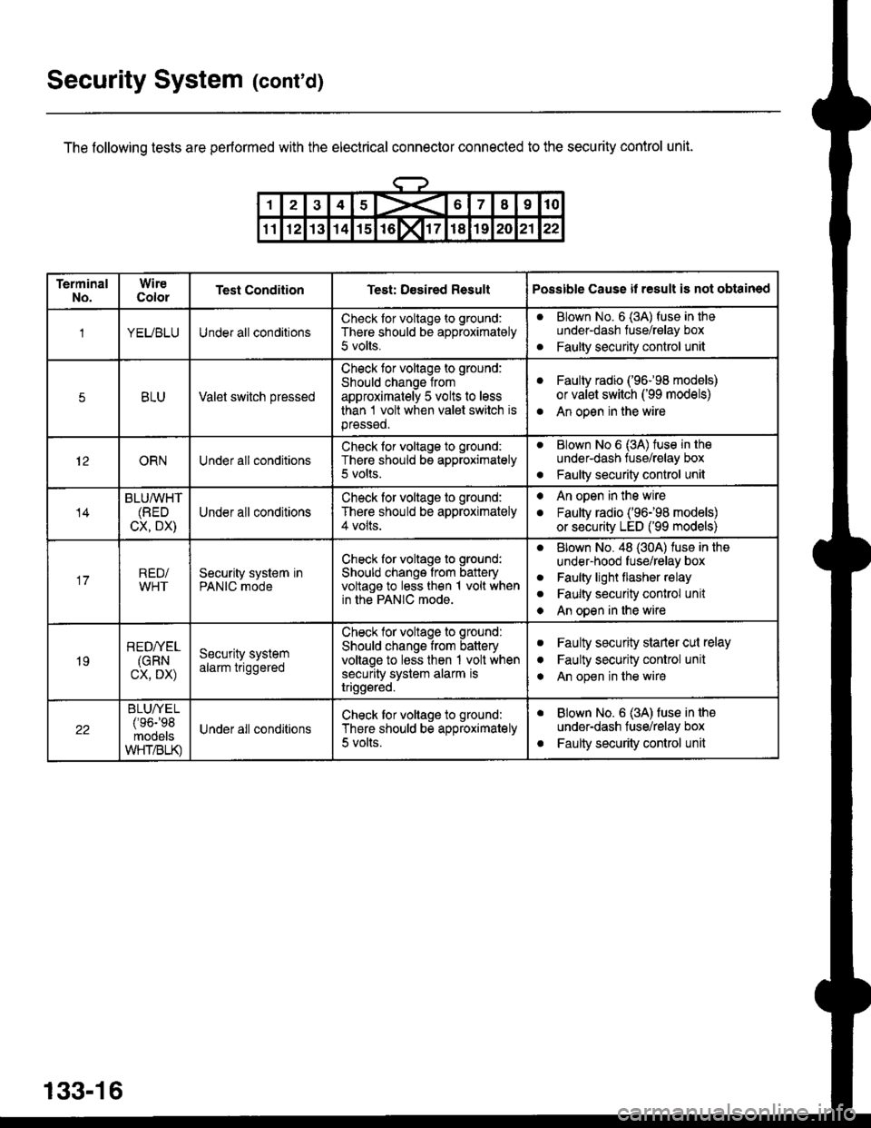
Security System (cont'd)
The following tests are performed with the electrical connector connected to the security control unit.
133-16
TerminalNo.WireColorTest ConditionTest: Desired ResultPossible Cause il result is not obtained
1YEUBLUUnder all conditionsCheck tor voltage to ground:
There should be approximately
5 volts.
aBlown No. 6 (3A) fuse in theunder-dash fuse/relay box
Faulty security control unita
5BLUValet switch pressed
Check tor voltage to ground:
Should change from
approximately 5 volts to less
than 1 volt when valet switch isprsssed.
aFaulty radio ('96-98 models)
or valet switch ('99 models)
An open in the wirea
12ORNUnder all conditionsCheck for voltage to ground:
There should be approximately5 volts.
aBlown No 6 (3A) tuse in tho
under-dash tuse/relay box
Faulty security control unito
14
BLU/WHT(BED
CX, DX)Under all conditions
Check for voltage to ground:
There should be approximately4 volts.
. An open in the wire
. Faulty radio ('96198 models)
or security LED ('99 models)
17RED/WHTSecurity system inPANIC mode
Check for voltage to ground:
Should change from batteryvoltage to less then 1 volt whenin the PANIC mode.
aBlown No. 48 (30A) luse in the
under-hood fuse/relay box
Faulty light flasher relay
Faulty security conlrol unit
An open in the wire
a
a
a
19
REDI/EL(GRN
cx, DX)
Security systemalarm triggered
Check tor voltags to ground:
Should change from batteryvoltage to less then 1 volt whensecurity system alarm istriggsred.
aFaulty security starler cut relay
Faulty security control unit
An open in the wire
I
a
22
BLUA/EL/'oa-'oq
mooelsWHT/BLK)
Under all conditionsCheck tor voltage to ground:
There should be approximately
5 volts.
aBlown No. 6 (3A) fuse in the
under-dash fuse/relay box
Faulty security control unita
Page 2059 of 2189
\.
\iu
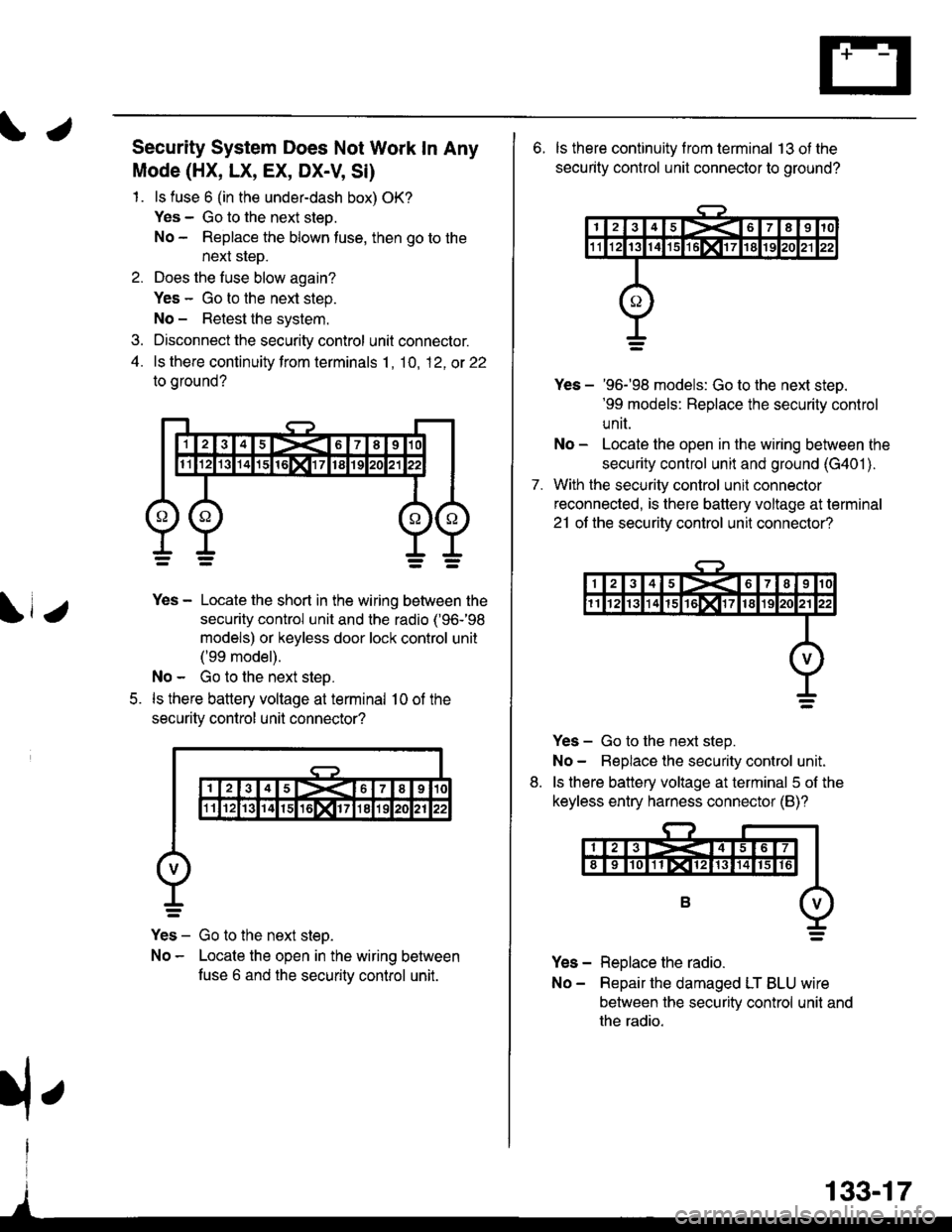
Security System Does Not Work In Any
Mode (HX, LX, EX, DX-V, Si)
1. ls fuse 6 (in the under-dash box) OK?
Yes - Go to the next steo.
No - Replace the blown tuse, then go to the
next sleD.
2. Does the fuse blow again?
Yes - Go to the next step.
No - Retest the system.
3. Disconnect the security control unit connector.
4. ls there continuity from terminals 1, 10, 12, ot 22
to oround?
5.
Yes - Locate the short in the wiring between the
security control unit and the radio ('96-'98
models) or keyless door lock control unit
('99 model).
No - Go to the next step.
ls there battery voltage at terminal 10 of the
securitv control unil connector?
Yes - Go to the next steo.
No - Locate the open in the wiring between
fuse 6 and the securitv control unit.
133-17
rfe
6. ls there continuity f rom terminal 13 ot the
security control unit connector to ground?
7.
Yes - '96-'98 models: Go to the next steD.'99 models: Replace the security control
unit.
No - Locate the open in the wiring between the
security control unit and ground (G401 ).
With the security control unil connector
reconnected, is there battery voltage at terminal
21 ot the securitv control unit connector?
Yes - Go to the next step.
No- Beplace the security control unit.
ls there battery voltage at terminal 5 of the
keyless entry harness connector (B)?
Yes - Replace the radio.
No- Repair the damaged LT BLU wire
between the security control unit and
the radio.
8.
Page 2062 of 2189
Security System (cont'd)
Security System Does Not Disarm With
The Transmitter (HX, LX, EX, DX-V, Si)
1 . With all the doors closed and locked, do the
doors unlock when the transmitter UNLOCK
button is pressed?
Yes - Go to the next step.
No - Go to "Doors Do Not Unlock With The
Transmitte/' on page 130-11 ('96-98
models) or 130-18 ('99 models).
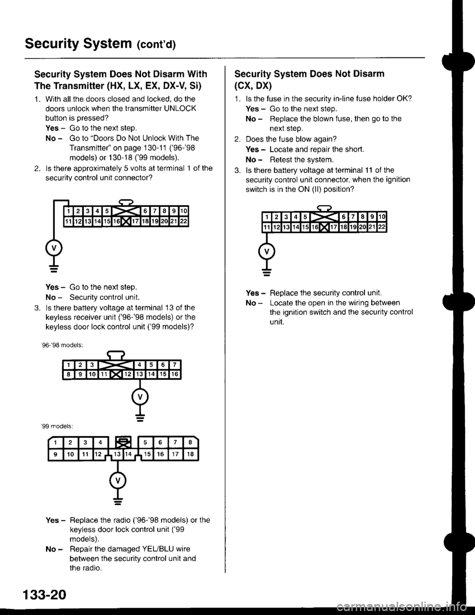
2. ls there approximately 5 volts at terminal 1 of the
securitv control unit connector?
Yes - Go to the next step.
No - Security control unit.
3. ls there battery voltage at terminal 13 ofthe
keyless receiver unit ('96-�98 models) or the
keyless door lock control unit ('99 models)?
96.�98 models:
'99 models:
Yes - Beplace the radio ('96-'98 models) or the
keyless door lock control unit ('99
models).
No - Repair the damaged YEUBLU wire
between the security control unit and
the radio.
133-20
Security System Does Not Disarm
(cx, Dx)
1. ls the tuse in the security in-line luse holder OK?
Yes - Go to the next step.
No - Replace the blown fuse, then go to the
nexl sreD.
2. Does the fuse blow again?
Yes - Locate and repair lhe short.
No- Retest the system.
3. ls there battery voltage at terminal 11 of the
security control unit connector, when the ignition
switch is in the ON (ll) position?
Yes - Replace the security control unil.
No - Locate the open in the wiring between
the ignition switch and lhe securily control
unit.
Page 2063 of 2189
rl,Security System Does Not Disarm With
The Valet Switch
Security System Does Not Work ln The
Valet Mode ('96-'98 HX, LX, EX)
1. ls luse 3 (in the under-dash fuse box) OK?
Yes - Go to the next steD.
No - Replace the blown fuse, then go to the
next step.
2. Does the fuse blow again?
Yes - Locate and reoair the short.
No - Retest the system.
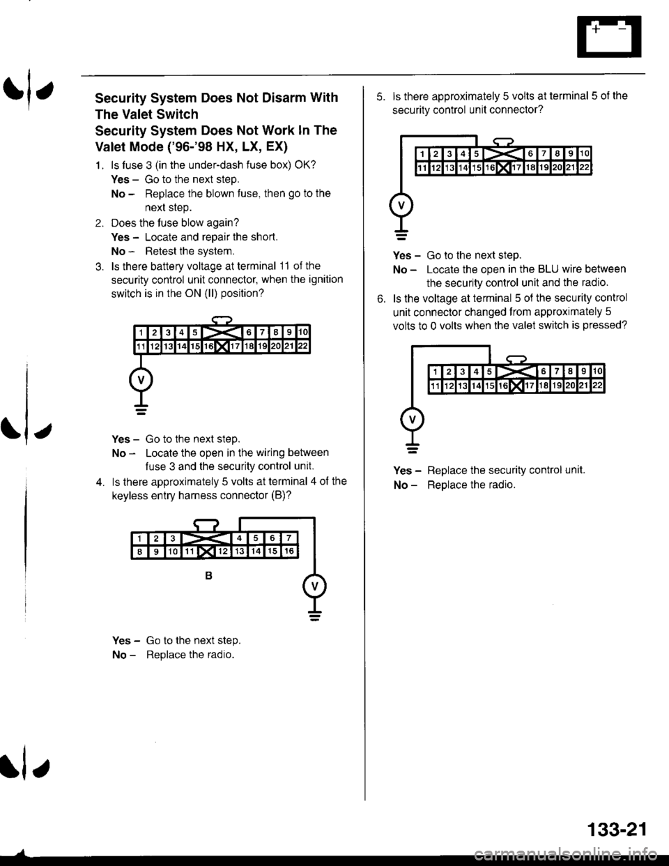
3. ls there battery voltage at terminal 11 of the
security control unit connecto( when the ignition
switch is in the ON (ll) position?
Yes - Go to the next step.
No - Locate the open in the wiring between
luse 3 and the security control unit.
ls lhere approximately 5 volts at terminal 4 of the
keyless entry harness connector (B)?
Yes - Go to the next step.
No - Replace the radio.
rl e
133-21
5. ls there approximately 5 volts at terminal 5 of the
security control unit connector?
Yes - Go to the next step.
No - Locate the open in the BLU wire between
the security control unit and the radio.
ls the voltage at terminal 5 oJ the security control
unit connector changed from approximately 5
volts to 0 volts when the valet switch is pressed?
Yes - Replace the security control unit.
No - ReDlace the radio.
6.
Page 2124 of 2189
-57. c723
- Connects heater-sub-A wire harness to
heater-sub-B wire harness
'96-'98 Models:- Gray- Below right side of dash
l BLUAVHT(Blower controls)
2 BLU (Blower controls)
3 YEL (Air delivery)
4 WHT/BLU (A/Ccompressor controls)
5 RED (Dash lights)
6 GRN^VHT (Air delivery)
7 GRN/RED (A r delivery)
I BLUAVHT (Air delivery)
9 BLK,ryEL (Air delivery)
10 YEUBLU (Air delivery)
11 BLU/YEL(Blower controls)
12 BED/BLK (Dash lights)
13 BLK (G402)
t4
15 BLK (Blower conlrols)
16 BLU/BLK(Blower controls)
18 BLU/RED (A/C
compressor controls)
19 GRN/YEL (Air delivery)
20 YEURED (Air delivery)
'99-'00 Models:- Blue- Behind center ot dash
1 RED/BLK (Dash lights)
2 BRNMHT (Au delivery)
4 GRNA/VHT (Air delvery)
5 GBN/BED (Air delivery)
6 GRN/YEL (Alr delivery)
7 YEURED (Air delivery)
8 BLU,ryVHT (Au delivery)
9 YEL (An delivery)
10 YEUBLU (Arr delivery)
11 LT GRN/BLK(Blower controls)
12 ORN,AiVHT(Blower controls)
13 BBN (Air delivery)
14 RED (Dash lights)
15 GRY (Air delrvery)
16 RED,ryVHT (Air delivery)
17 RED/YEL (Air delivery)
18 PNK/BLK (Air delivery)
19
20 BLU/RED (A/C
compressor controls)
21 BLUI/EL(Bear window defogger)
22 WHT/BLU (Fuse 47)
23 BLKryEL (Fuse 17)
24 BLK \G402)
I
1415617I910
1l1213141617181920
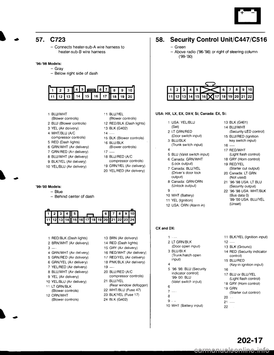
58. Security Control UnitiC447lC516
- Green- Above radio ('96-�98) or right of steering column
(99-'�00)
USA: HX, LX, EX, DX-V Si; Canada: EX, Si:
1 USA: YEUBLU(Set)
2 LT GRN/RED(Door swiich input)
3 BLU/BLK(Trunk switch rnput)
4
5 BLU (valet switch inpu0
6 Canadai GFNAVHT(Lock output)
7 Canada: BLU/YEL(Driver's door lockoulpurJ
I Canada: GRN/OBN(Unlock output)
9
10 WHT (Battery)
11 YEL (lgnition)
12 USA: OHN (Alarm in)
CX and DX:
1
2 LT GRN/BLK(Door open input)
3 BLU/BLK(Trunk/hatch openinput)
5 '96 '98: BLU (Security
ndicator control)99- 00: BLU(Valel switch input)
6
7
B
I
10 WHT (Battery input)
13 BLK (G401)
14 BLUMHT(Security LED conkol)
15 BLU/RED (lgnitionkey switch input)
17 REDAVHI(Light flash control)
18 GRY (Horn conkol)
19 RED/YEL(Starter cut output)
20 Canada: LT GRN(Nol used)
21 ,96-,98 USA: LT BLU(Security output)
22 '96 98 USA: WHT/BLK(Bus data 0)'99-'00 USA: BLU/YEL(Unset)
11 BLK/YEL (lgnition input)
13 BLK (Ground)
14 RED (Security indicatorcontrol)
15 BLU/RED(Key in ignition input)
16
17 BLU or BLU/YEL(Light tlash control)
18 GRY (Horn control)
19 GRN(Slarter cut control)
20
22
1><678910
1112131415rGlxllT1819202122
202-17
Page 2131 of 2189
Gonnector Views (cont'd)
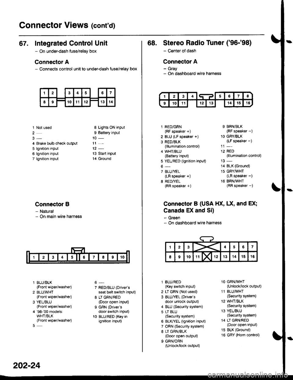
67. Integrated Control Unit
- On underdash fuse/relay box
Connector A
- Connects control unit to under-dash fuse/relay box
1 Not used
4 Erake bulb check output
5 lgnition input
6 lgnition input
7 lgnjtion input
Connectol B
- Natural- On main wire harness
l BLU/BLK
{Front wiper/washer)
2 BLUA/VHT(Front wiper/washe0
3 YEUBLU(Front wiper/washer)
4 '98-'00 models:WHT/BLK(Front wiper/washer)
8 Lights ON input
9 Battery input
11 _
13 Start input
14 Ground
7 RED/BLU (Driver's
seat b€lt switch input)
8 LT GRN/RED(Door open input)
I GRN (Oriver's
door switch input)'t0 BLU/RED (Key inignition input)
202-24
68. Stereo Radio Tuner ('96-'98)
- Center ot dash
Connector A
- Gray- On dashboard wire harness
1 RED/GRN(RF speaker +)
2 BLU (LF speaker +)
3 RED/BLK(lllumination control)
4 WHT/BLU(Battery input)
5 YEURED (lgnition input)
6-
7 BLU/YEL(LR speaker +)
8 RED/TEL(RR speaker +)
9 BRN/BLK(RF speaker -)
1O GRY/BLK(LF speaker -)
12 RED(lllumination control)
14 BLK (Ground)
15 GFY,4/VHT(LR speaker -)
16 BRNAVHT(RR speaker -)
Connector B (USA HX, UX, and EX;
Canada EX and Si)
- Green- On dashboard wire harness
l BLU/RED(Key switch input)
2 LT GRN (Not used)
3 BLU/'EL (Drivels
door unlock output)
4 BLU (Security system)
5 LT BLU
{Security system)
6 BLIVYEL (lgnition input)
7 ORN (Security system)
8 LT GRN/BLK(Door open output)
9 GRN/ORN(Unlock/lock output)
1O GRNAVHT(Unlock/lock output)
1 1 BLU/WHT(Security system)
'2 WHT/BLK(Security system)
13 YEUBLU(Security system)
14 LT GRN/RED(Door open input)
15 BLK (Ground)
16 GRY (Horn conkol)