Page 877 of 2189
ATF PUMPDRIVEN SPROCKET
RING GEAR
FLYWHEEL
DRIVE PLATE
ATF PUMP
DRIVE PULLEYREVERSE BRAKEPISTON
FORWARD CLUTCH
BEVERSE BRAKE
CARRIER
RING GEAR
PLANETARYPINION GEARS
INPUT SHAFT
ATF PUMPDRIVE CHAIN
ATF PUMPDRIVE SPROCKET
START CLUTCH
DRIVEN PULLEY
STEEL BELT
SECONDARY DRIVE GEAR
PARK GEAR
DRIVEN PULLEYSHAFT
FINAL DRIVE GEAR
SECONDARY GEARSHAFT
a--
i___
il
14-199
Page 879 of 2189
E, E, and E Positions {Forward Rangel
. Sta rt Clutch: engaged
. Forward Clutch: engaged
o Reverse Brake: released
1, The hydraulic pressure is applied to the forward clutch and the start clutch, and the sun gear drives the torward
clutch.
2. The torward clutch drives the drive pulleV shaft. which drives the driven pulley shaft linked by the steel belt.
3, The driven pulley shaft drives the secondary drive gear, via the start clutch.
4. Power is transmitted to the secondary driven gear, which drives the final driven gear.
NOTE: The working hydraulic pressure on the movable face of each shaft depends on the throttle opening position.
DRIVE PULI.f YFLYWHEELSTEEL AELT
CLUTCH
INPUT SHAFT
START CLUTCH
SECONDARY DRIVENGEAR
(cont'd)
FINAL DRIVEN GEAR
14-201
Page 972 of 2189

t.
rl,
fl,
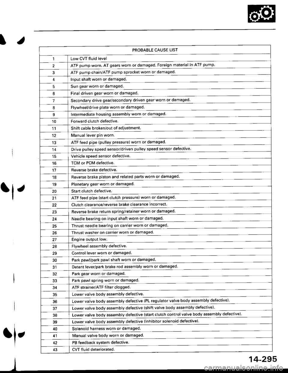
PROBABLE CAUSE LIST
Low CVT fluid level
ATF pump worn. AT gears worn or damaged. Foreign material in ATF pump.
ATF pump chain/ATF pump sprocket worn or damaged.
Input shaft worn or damaged.
Sun gear worn or damaged.
Final driven oear worn or damaqed,
Secondary drive gear/secondary driven gear worn or damaged-
5
6
1
8Flywheel/drive plate worn or damaged.
Intermediate housing assembly worn or damaged.9
'10Forward clutch defective.
Shift cable broken/out of adiustment.
M"nu"t t"uffi
ATF feed pipe (pulley pressure) worn or damaged.
Vchiclc speed sensor defective.
TCM or PCM defective.
Reverse brake detective.
1'�r
't2
13
14
16
'11
'18
1qPlanetary gear worn or damaged.
Sta rt clutch defective.
ATF feed pipe (start clutch pressure) worn or damaged
20
t't
Clutch clearance/reverse brake clearance incorrect.
23Reverse brake return spring/retainer worn or damaged
24Needle bearing on input shaft worn or damaged.
25Thrust needle bearing on carrier worn or damaged.
Thrust washer on carrier worn or damaged.
Enoine outout low.------------------------
Flvwhcel assemblv defective.
Control lever worn or damaged.
Park pawl/park pawl shaft worn or damaged
Detent lever/park brake rod assembly worn or damaged
27
29
30
32Park gear worn or damaged.
Park pawl spring worn or damaged.
ATF strainer/ATF filter clogged.
Lower valve body assembly defective.
Lower valve bodv assemblv defective (PL regulator valve body assembly defective)'
33
34
50
Lower valve bodv assembly defective (shift valve body assembly defective).
Lower valve bodv assemblv defective (start clutch control valve body assembly defective)'
39Lower valve bodv assemblv defective {inhibitor solenoid defective}
40Solenoid harness worn or damaged.
Manual valve body worn or damaged.
PB feedback system defective.
CVT fluid deteriorated.
41
43
14-295
Page 983 of 2189

Transmission
Removal (cont'd)
10. Remove the cotte. pins and castle nuts, then separatethe ball joints from the lower arm (see section 1g).
SELF-LOCKING -=V,
NUT \Replace. oitupea rOax
Remove the right damper fork bolt, then separateright damper fork and damper.
Pry the right and left driveshafts out of the differen-tial.
Pull on the inboard joint to remove the right and leftdriveshafts (see section 16).
Tie plastic bags over the driveshaft ends.
NOTE: Coat all precision finished surfaces with cleanengine oil.
Remove the exhaust pipe A.
/\<,\CASTLE I{UT COTTERReplac6.
't 1.
't2.
tJ.
14.
q.
SELF.LOCKINGNUTReplace.
SELF.LOCKING NUTReplace.
14-306
EXHAUST PIPE A
19.
'16, Remove the right front mounvbracket,
ATF COOLER HOSE
17. Remove the ATF cooler hoses at the ATF coolerlines. Turn the ends of the ATF cooler hoses uo toprevent CVT fluid from flowing out, then plug theATF cooler hoses and lines,
NOTE: Check for any sign of leakage at the hosejoints.
18. Remove the engine stiffeners and the flywheel cover.
Remove the eight drive plate bolts one at time whilerotating the crankshaft pullev.
ENGINE STIFFENER
Page 987 of 2189
lllustrated Index
Transmission Housing/Flywheel Housing
8G
I
)
H
14-310
Page 988 of 2189

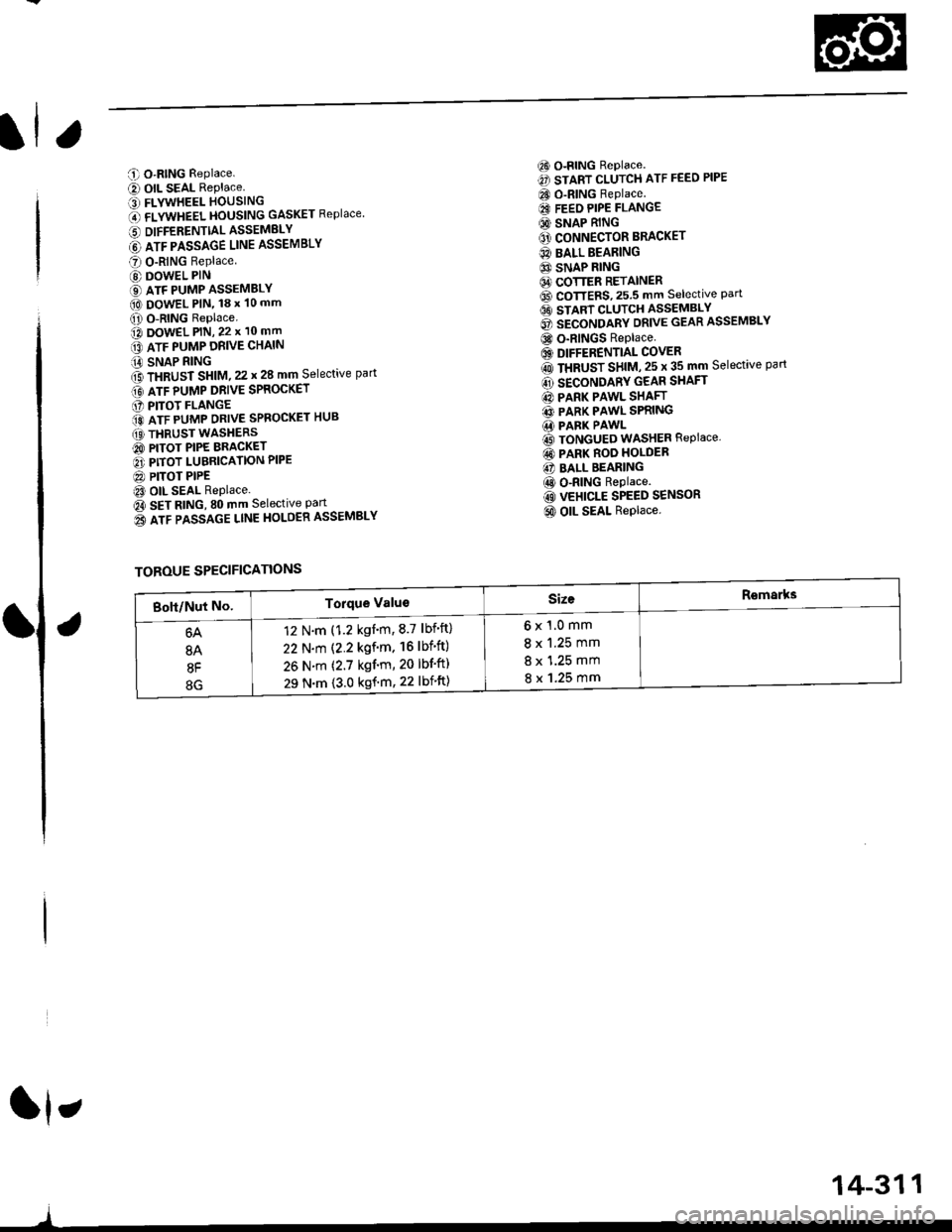
C O-RING Replace.
e) OIL SEAL RePlace.' FLYWHEEL HOUSING
O flVWneel }|OUSttttG GASKET Replace
6 DIFFERENTTALASSEMELY
@ lrr plsslce uruE ASSEMBLY
O O-RING Replace
@ DOWEL PIN
€) ATF PUMP ASSEMBLY(O DowEL PlN, 18 x 10 mm
O O-RING Replace.o DowEL PlN, 22 x 10 mm
lrr puup oRve cxltttt
iA SNAP RING
f3 fxaUst St|t|l, zz t 28 mm Selective part
Gt lrr punp ontve spaocxer
O PITOT FLANGE
ito nTF purrap ontve SPRoGKET HUB
(O THRUST WASHERS
@ PITOT PIPE BRACKET
O PITOT LUBRICATION PIPE
@ PITOT PIPEt3 OIL SEAL Replace.
Oa SEt AtitC, SO mm Selective Part
o3 lrr passlce ltnE HoLOER ASSEMBLY
6) o-RING Replace.
€) START CLUTCH ATF FEED PIPE
CO O-RING Replace.
€I FEEO PIPE FLANGE
@ SNAP RING
O' CONNECTOR BRACKET
@ BALL BEARING
6} SNAP RING64 COTTER RETAINER6D CoTTERS,25.5 mm selective Part6t stlnt cLutcH asseMsLv
@ secoruomv ontvE GEAR ASSEMBLY
@ o-RINGS Replace
6) DIFFERENTIAL COVER
rO ttaUSr SntU, zs t 35 mm Selective part
@ SECONDARY GEAR SHAFT
@ PARK PAWL SHAFT
@ PARK PAWL SPRING.1i PARK PAWL
@ TONGUED WASHER REPIACE,
@ PARK ROO HOLDER
@ BALL BEARING
@ o-RING Replace.
@ VEHICLE SPEED SENSOR
@ OIL SEAL Replace.
ft,
)
TOROUE SPECIFICATIONS
6x1.0mm
8 x 1.25 mm
8 x 1.25 mm
8 x 1.25 mm
12 N.m (1.2 kgnm,8.7 lbf'ft)
22 N.m (2.2 kgf'm. 16lbf'ft)
26 N.m (2.7 kgf'm, 20 lbf'ft)
29 N.m {3.0 kgf'm, 22 lbift)
14-311
Page 993 of 2189
Transmission Housing/Flywheel Housing
Removal
NOTE:
. Cleanall parts thoroughly in solvent or carburetor cleaner, and dry with compressed air.. Blow out all passages.
. When removing the transmission housing/flywheel housing, replace the following:- O-rings- Secondary drive gear assembly- Sta rt clutch assemblv- Flywheel housing gasket
ATF PASSAGE LINEHOLD€R ASSEMBLY
IX)WEL PIN
OIFFERENTIAL ASSEMBLY
SNAP RING
COTTER RETAINER
COTTERS, 25.5 mmSelective part
8 x 125 mm BOLT
O.RINGRsplaco.
VWHEEL HOUSING
EYWIIEEL HOUSING GASKETRoolace.
START CLUTCHASSEMBLYReplace.
ATF PA$gAGEUNE ASSEMBLY
6 x 1,0 mm BOLT
O.RINGReplace.
ATF PUMP DRIVE CHAIN
SNAP RING
THRUST SHIM,25x35mmSeloctive part
SECONDARYGEAR SHAFT
SECONDARY DRIVEGEAR ASSEMBLYReplace.
PARKPAWL SHAFT
THRUST SHIM, 22 r 28 mmSeloctive partGRII{GSReplac€.6 x 1.0 mm BOIT
ATF PUMP DRIVESPROCKET
PfTOT FLANGE
ATF PUMP DRTVESPROC|(ET HUB
THRUST WASHERS
PARK PAWLSPRING
INPUT SHAFT
14-316
DRIVEN PULLEY SHAFT
InANSMISS|O]{ HOUSTNG
Page 994 of 2189

)
1.Remove the ATF passage line holder assembly'
Remove the flywheel housing (twenty bolts)'
Remove the ATF passage line assembly (one bolt)
Remove the ATF pump drive sprocket (three bolts),
then remove the ATF pump drive chaan.
Move the pitot flange toward its cutout, then remove
the pitot flange.
PITOT PIPE
Remove the snap ring securing the ATF pump drlve
sprocket hub. then remove the 22 x 28 mm thrust
shim, the ATF pump drive sprocket hub and the thrust
wasners,
Remove the differential assemblY.
Remove the park pawl shaft, the park pawl spring,
and the park Pawl'
Remove the snap ring securing the start clutch, then
remove the cotter retainer and the cotters.
7.
9.
J
14-317
10. Set the special tool on the start clutch' and attach the
oawl of the special tool to the park gear securely as
shown.
CAUTION:
. Do not place tho pawl of the spocial tool on the
start clutch guidc. ll the pawl ot the spocial tool
contacts the 3tart clutch guid€, the start clutch
guido may be damaged.
. Be sure not to allow dust and other foreign par-
ticles to enter into the drivon pull6y shaft'
START CLUTCHREMOVER07TAE - P4V0120
11.Remove the start clutch and the secondary drive
gear assembly using the special tool, then remove
the secondary gear shaft.
START CLUTCHREMOVER07TAE - P4V0120
START CLUTCHASSEMBLYReplace.
START CLUTCHASSEMBLY
PAWL