Page 1062 of 2189
Steering Gearbox
Removal(cont'd)
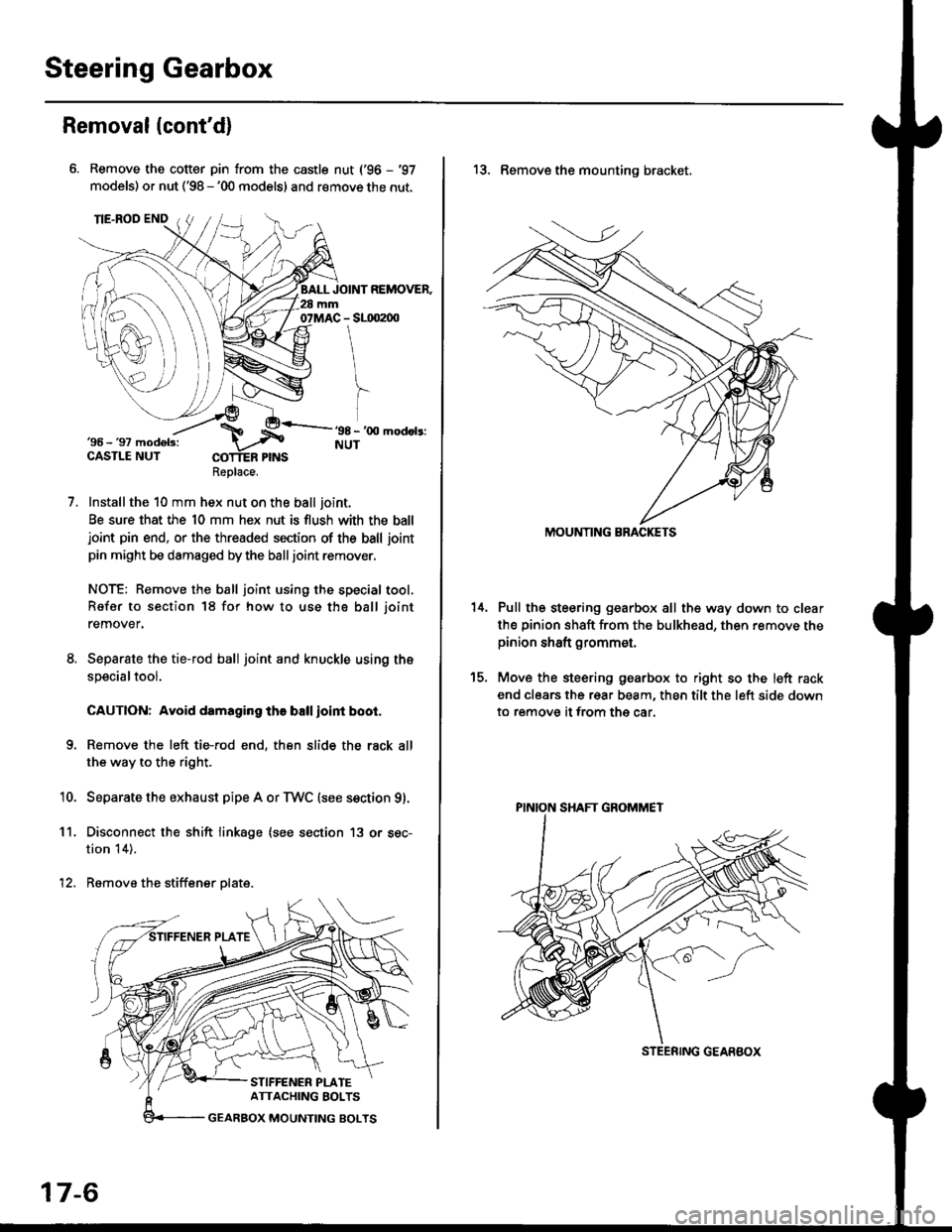
Remove the cotter pin from the castle nut ('96 - '97
models) or nut ('98 - '00 models) and remove the nut.
Installthe 10 mm hex nut on the ball joint.
Be sure that the 10 mm hex nut is flush with the balljoint pin end, or the threaded section of the ball joint
pin might be damaged by the balljoint remover.
NOTE: Remove the ball joint using the special tool,
Refer to section 18 for how to use tho ball joint
remover.
Separate the tie-rod ball joint and knuckle using the
specialtool.
CAUTION: Avoid damaging the ball ioint boot.
Remove the left tie-rod end, then slide the rack all
the way to the right.
Separate the exhaust pipe A or TWC (see section g).
Disconnect the shift linkage (see section 13 or sec-
tion 14).
Remove the stiffener plate.
7.
'10.
11.
12.
Replace.
17-6
13. Remove the mounting bracket,
Pull the steering gearbox all the way down to clear
th€ pinion shaft from the bulkhead, then remove thepinion shaft grommet,
Move the steering gearbox to right so the left rack
end clears the rear beam, then tilt the left side down
to remove it from the car.
t5.
STEENING GEARBOX
PINION SHAFT GROMMET
Page 1103 of 2189
Steering Gearbox
)
Removal
NOTE: Using solvent and a brush, wash any oil and dirt
off the valve body unit its lines. and the end if the gear-
box. Blow dry with comPressed air.
1. Drain the power steering fluid as described on page
2. Raise the front of vehicle, and support it on safety
stands in the proper locations (see section 11.
3, Remove the front wheels.
4. Remove the driver's airbag assembly, and steering
wheel (see page 17-35)
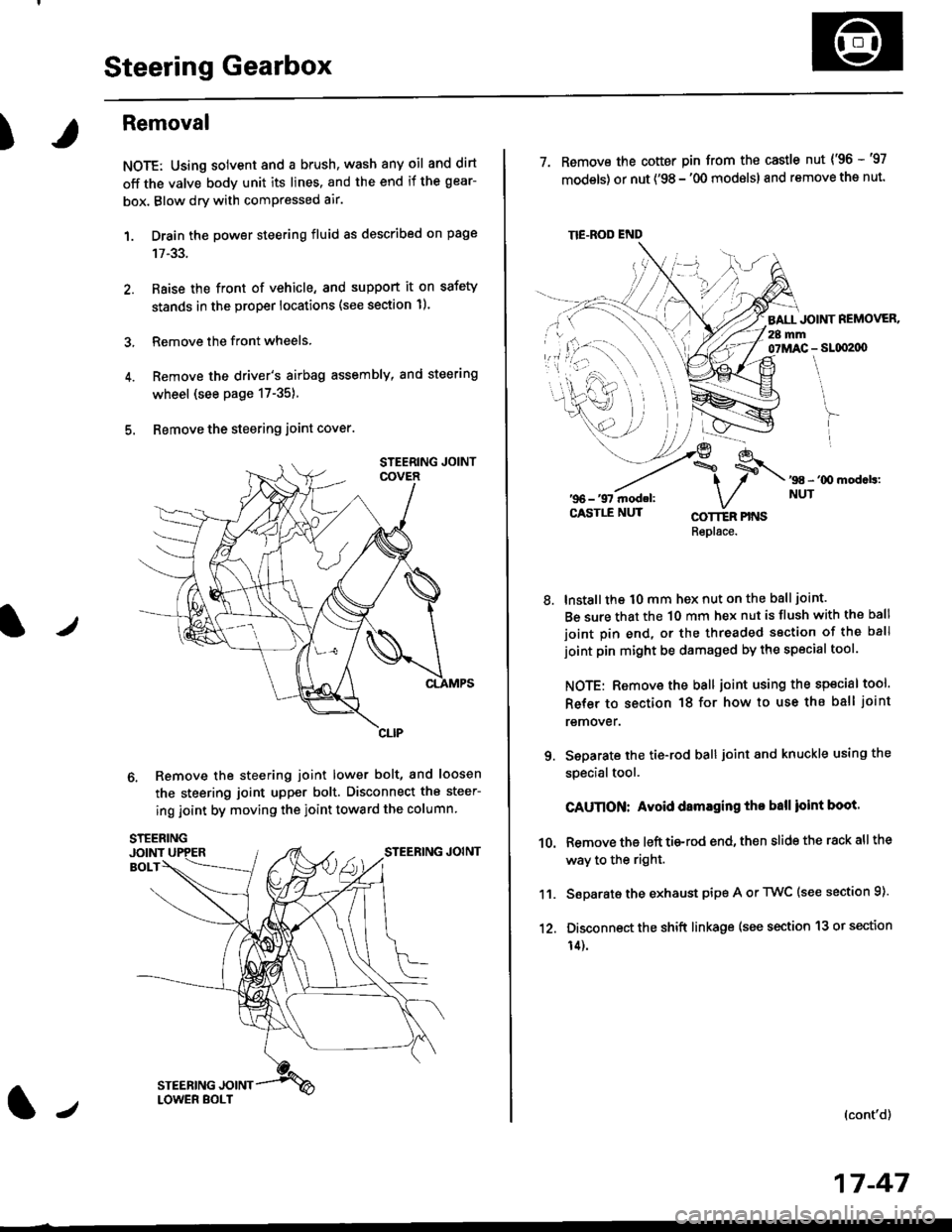
5. Bemove the steering joint cover.
6. Remove the steering joint lower bolt, and loosen
the steering joint upper bolt. Disconnect the steer-
ing joint by moving the ioint toward the column
tJ
17-47
TIE.ROD END
7. Remove the cotter pin from the castle nut {'96 -'97
models) or nut ('98 - '00 modslsl and remove the nut.
BALL JOINT REMOVER.28 mm07MAC - SLqI2|X)
'98 - '00 mod.b:NUT
8.
COTTER PINSRepl6ce.
lnstall the t0 mm hex nut on the ball joint.
Be sure that the 10 mm hex nut is flush with the ball
joint pin end, or the threaded section of the ball
joint pin might be damaged by the special tool.
NOTE: Remove the ball joint using the special tool.
Refer to section 18 for how to use ths ball joint
remover.
Seoarate the tie-rod ball joint and knuckle using the
specialtool.
CAUnON: Avoid damaging tho ball ioint boot.
Remove the left tie-rod end, then slide the rack all the
way to the right.
Separate the exhaust pipe A or TWC (see section 9).
Disconnect the shift linkage (see section 13 or section
14).
(cont'd)
9.
10.
11.
12.
Page 1136 of 2189
Front Suspension
Knuckle/Hub Replacement (cont'dl
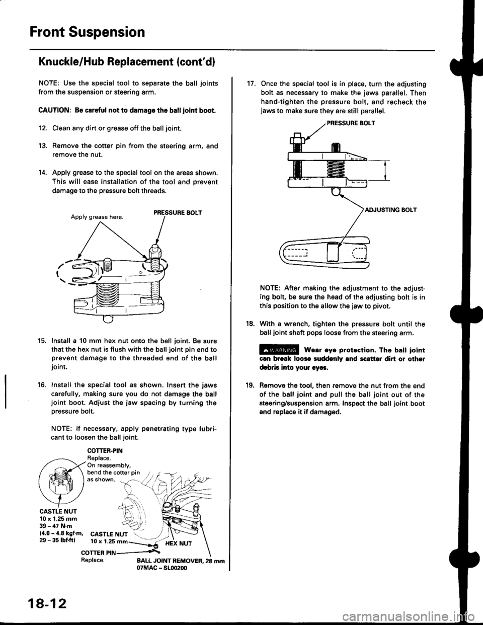
NOTE: Use the special tool to separate the ball joints
from the suspension or steering arm,
CAUTION: 86 careful not lo damage the ballioint boot.
12. Clean any din or grease off the ball joint.
13. Remove the cotter pin from the steering arm, and
remove the nut.
14. Apply grease to the special tool on the areas shown,
This will ease installation of the tool and prevsnt
damage to the pressure bolt threads.
PRESSURE AOLT
Install a 10 mm hex nut onto the ball joint. Be sure
that the hex nut is flush with the ball joint pin end toprevent damage to the threaded end of the balljoint.
Install the special tool as shown. Insert the jaws
carefully, making sure you do not damage the balljoint boot. Adiust the iaw spacing by turning th6pressure bolt.
NOTE: lf necessary, apply penetrating type lubri-
cant to loosen the ball joint.
COTTER.PINReplace.On reassembly,bend the cofter pin
15.
16.
CASTI.T NUT10 x 1,25 mm39 - 47 N.m14.0 - 4.8 kgf.m,29 - 3s tbl.fttCASTLE NUT10 r 1.2s mn--]*-
corrcn nn .\
18-12
Replace-
17. Once the special tool is in place, turn ths adjusting
bolt as necessary to make the jaws parallel. Then
hand-tighten the pressure bolt, and recheck thejaws to make sure they are still parallel.
AI\IUSTING BOLT
NOTE: After making the adiustment to the adiust-
ing bolt, be sure the head of the adjusting bolt is in
this position to the allow the jaw to pivot.
With a wrsnch, tighten the pressure bolt until the
ball joint shaft pops loose from the steering arm.
E@ we.r cye plotection. Thc brtt iointcln brcrk loose suddenly and sclt'tol dirt or other
d.brb inio youl .ye..
Rsmov€ the tool, then remove th€ nut from the end
of the ball ioint and pull the ball joint out of the
stoering/suspension arm. Insp€ct the ball joint boot
and replace it if damaged.
18.
10
Page 1137 of 2189
)
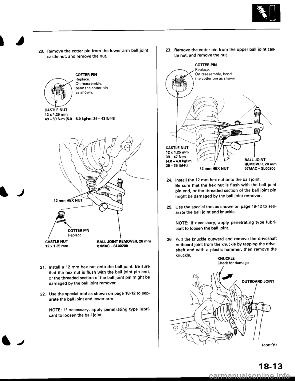
20, Remove the cotter pin from the lower arm ball joint
castle nut. and remove the nut.
COTTER.PINReplace.On reassembly,bend the cotter Pan
lr
CASTLE NUT12 x 1.25 mm49 - 59 N.m (5.0 - 6.0 kgl m,36-,13 lbf'ft|
BALL JOINT REMOVER, 28 mm
07MAC - SL00200
21. lnstall a 12 mm hex nut onto the ball joint. Be sure
that the hex nut is flush with the ball joint pin end'
or the threaded section of the ball joint pin might be
damaged by the ball joint remover.
22. Use the special tool as shown on page l8-12 to sep-
arate the ball ioint and lower arm.
NOTE; lf necessary, apply penetrating type lubri-
cant to loosen the ball joint.
lJ
18-13
25.
26.
Remove the cotter pin from the upper ball joint cas-
tle nut, and remove the nut.
12 mm HEX NUT 07MAC - SL00200
lnstall the 12 mm hex nut onto the ball joint
Be sure that the hex nut is flush with the ball joint
pin end, or the threaded section of the ball joint pin
mlght be damaged by the ball joint remover'
Use the special tool as shown on page l8-12 to sep-
arate the ball joint and knuckle.
NOTE: lf necessary, apply penetrating type lubri
cant to loosen the ball joint.
Putl the knuckte outward and remove the driveshaft
outboard joint from the knuckle by tapping the drive-
shaft end with a plastic hammer, then remove the
knuckle.KNUCKLE
'12 x 1.25 mm39 - 47 N.m
14.0 - 4.8 kgf m,29 - 35 tbf.ft)
Check for damage.
Page 1149 of 2189
T
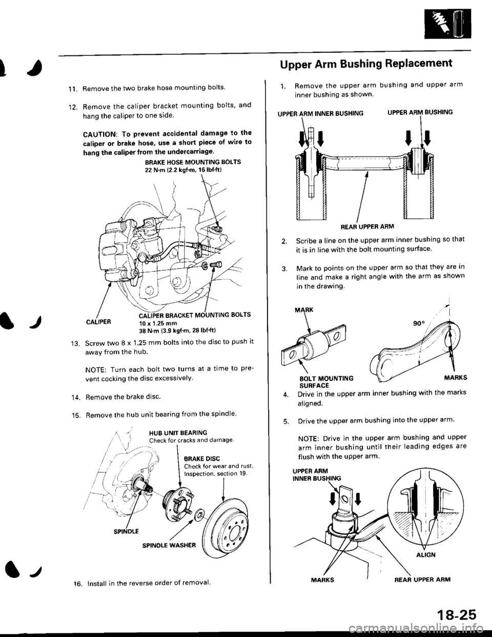
11.
1)
Remove the two brake hose mounting bolts
Remove the caliper b.acket mounting bolts, and
hang the caliPer to one side
CAUTION: To prevent accidental damage to the
caliper or brake hose, use a short piece of wile to
hang the caliper from the undercarriage.
BRAKE HOSE MOUNTING BOLTS
22 N'm {2.2 kgf'm, 16lbt"ft}
CALIPER 10 x 1.25 mm38 N'm (3.9 kgf'm, 28 lbf'ftl
Screw two 8 x 1.25 mm bolts into the disc to push it
away from the hub.
NOTE: Turn each bolt two turns at a time to pre-
vent cocking the disc excessively.
Remove the brake disc.
Remove the hub unit bearing from the spindle
SPINOLE WAS}IER
lr
14.
15.
lt
16. lnstall in the reverse order of removal.
1A-25
Upper Arm Bushing RePlacement
1. Remove the upper arm bushing and upper arm
jnner bushing as shown
UPPER ARM INNER BUSHING UPPER ARM BUSHING
REAR UPPER ARM
Scribe a line on the upper arm inner bushing so that
it is in line with the bolt mounting surface
Mark to points on the upper arm so that they are In
line and make a right angle with the arm as shown
in the drawing.
BOLT MOUNTINGSURFACE
Drive in the upper arm inner bushing with the marks
aligned.
Drive the upper arm bushing into the upper arm
NOTE: Drive in the upper arm bushing and upper
arm inner bushing until their leading edges are
flush with the uPPer arm
ttI
5.
UPPER ARM
Page 1253 of 2189
bPosition Adjustment
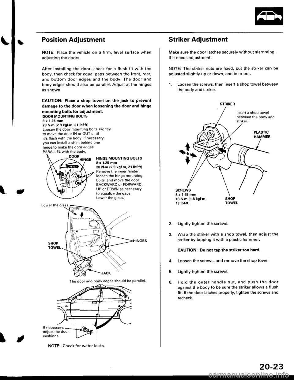
NOTE: Place the vehicle on a firm, level surface when
adjusting the doors.
After installing the door, check for a flush fit with the
body, then check for equal gaps between the front, rear,
and bottom door edges and the body. The door and
body edges should also be parallel. Adjust at the hinges
as shown,
CAUTION: Place a shop towel on the iack to prevent
damage to the door when loosening the door and hinge
mounting bohs for adiustment.
DOOR MOUNTING BOLTS8 x 1.25 mm28 N.m {2.9 kgf.m.21 lbt'ft}Loosen the door mounting bolts slightly
to move the door lN or OUT until
it's flush with the body. lf necessary,
vou can installa shim behind one
hinge to make the door edgesPARALLEL with the body.
J
HINGE MOUNTING BOLTSI x 1.25 mm28 N.m (2.9 kgf.m,21 lbtft)Remove the inner fender,loosen the hinge mountingbolts, and move the doorBACKWARD or FORWARD,UP or DOWN as necessaryto equalize the gaps.Lower the glass.
\
The door and body edges should be parallel-
ifF t
NOTE: Check for water leaks.
20-23
Striker Adjustment
lvlake sure the door latches securely without slamming.
lf it needs adjustment:
NOTE; The striker nuts are fixed, but the striker can be
adjusted slightly up or down, and in or out.
'L Loosen the screws, then insert a shop towel between
the body and striker.
Insert a shop towelbetween the body and
sc8Ews8 x 1.25 mm18 N.m (1.8 kgf.m,13 tbtftl
PLASTIC
2. Lightly tighten the screws.
3. Wrap the striker with a shop towel, then adjust the
striker by tapping it with a plastic hammer.
CAUTION: Do not tap the striker too hard.
4. Loosen the screws. and remove the shop towel.
Lightly tighten the screws.
Hold the outer handle out, and push the door
against the body to be sure the striker allows a flush
fit. lf the door latches properly, tighten the screws and
recheck.
5.
Page 1292 of 2189
Trunk Trim
Replacement
CAUTION:
. Put on gloves to proteci your hands.
. When prying with a flat-tip screwdriver, wrap it with protestive tap€ lo prevent damage.
NOTE:
. Take care not to bend or scratch the trim and panels.
. When removing the trunk side trim or trunk trim panel, fold the seat-back forward.
Japan-produced:
4D: RIGHT TRUNKSIDE TRIM
TRUNK MAT
1B
REAR TRIMPANEL
>: Clip locationsa>,6
a:-) ,2
I g cLlP ^
l#srq-'
| ' |NNER\- crLP
B >,6
NOTE: Do not push
the inner clip in too far.
IJ
LTro
i ) :Hook locations
A i--) , r
' 2D:
TRUNK TRIM
Installation is the reverse of the removal procedure.
NOTE:
. lf necessary. replace any damaged clips.
. To install the A clips. pull the inner clip up. install
the clip, then push the inner clip until it's flush.
(
,- --
/'/ \--
/ --
20-62
Page 1293 of 2189
Hatch Trim
>:Clip locationsa>,2NOTE: Do not push thlnner clip in too far.
& ct-tp.
54d-g+-\
2. INNF
Ijy. "
\
.V ft -s---
- k-"i-t-;-a-
Replacement
CAUTION:
. Put on gloves to protect your hands.
. When prying with a flat-tip screwdrivel, wrap it with protestive tape to prevent damage.
NOTE: Take care not to bend or scratch the trim and panel.
LEFT HATCHSIDE TRIM
HATCHUPPER TRIM
Installation is the reverse of the removal procedure.
NOTE:
. lf necessary, replace any damaged clips.
. ToinstalltheAclips,pulltheinnerclipup.installtheclip,thenpushtheinnerclipuntil it'sflush
a
I
20-63