1998 HONDA CIVIC Body electrical
[x] Cancel search: Body electricalPage 756 of 2189

Electrical Troubleshooting ('96 - 98 Models)
Th6 E indicstor light is on con-st.ntly {not blinkingl wheneveithe ignition switch is ON lll).
Measure 04 IND Voltage:1. Turn the ignition switch OFF.2. Disconnect the B 125P) connec-tor from the PCM.3. Turn the ignition switch ON (ll).
4. Measure the voltage betweenthe 813 terminal and bodyground,
Repair 3hort to pow€. in the wirobetween the 813 terminal endthc gauge asiombly.
Meaiure ATP Dil Voltage:1. Turn the ignition switch OFF.2. Connect the I (25P) connectorto the PCM.3. Turn the ignition switch ON (ll).4. Shiftto any position otherthan
5. Measure the voltage betweenthe 824 terminal and bodygrou nd.
Check for a short to ground on thowir6. It wire i3 OK, .eplac6 the A/Tgoar po3ition indbator,
Troubleshooting Flowchart - E Indicator Light On Constantly
a!
PCM CONNECTOR B (25P)
Wire side of lemale terminals
l.
14-7A
Page 762 of 2189

Electrical Troubleshooting ('gg - 00 Models)
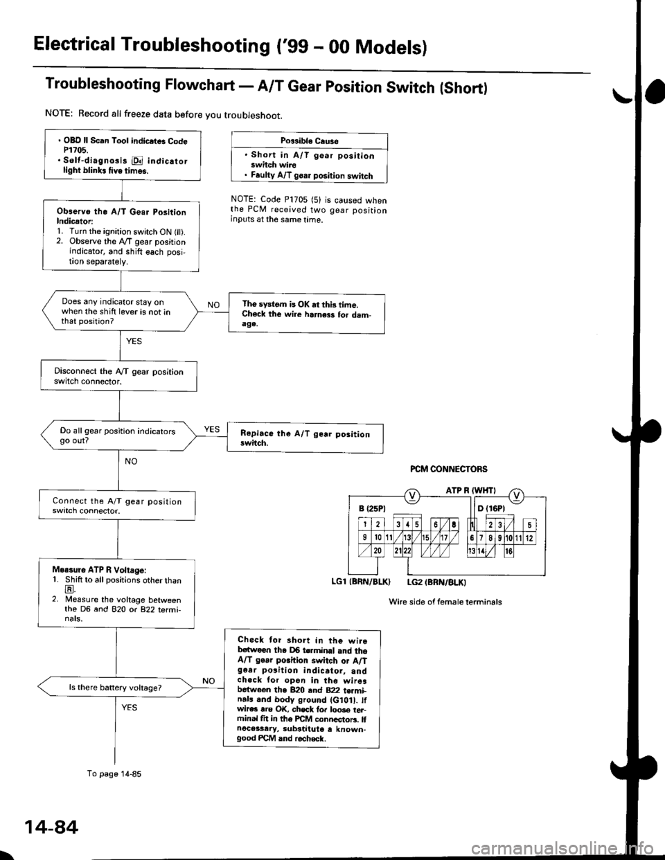
Troubleshooting Flowchart - A/T Gear position Switch (Short)
NOTE: Record all freeze data before you troubleshoot.
Po$ible Cause
' Short in A/T go.r positionswhch wire. Faulty A/T goar position switch
NOTE: Code P1705 (5)the PCM received twoinputs at the same time.
is caused whengear position
PCM CONNECTORS
LGl (BRN/BLK) LG2 (BRN/BLKI
Wire side of femaleterminals
B {25P1 llD (16P1
. OBD ll Scan Tool indicrtB CodeP1?05.. Solt-diagno3i3 E indicatorlight blink. tive times.
Observo the A/T Gear PositionIndicetori1. Turn the ignition switch ON fit).2. Observe the lVT gear positionindicator, and shift each posi,!on separately.
Does any indicator stay onwhen the shift lever is not inthat position?
The sFtom is OK at thi3 time.Check the wi.e harness for dam-aga.
Do all gear position indicatorsgo out?
Moasure ATP R Voltage:1. Shift to all positions otherthanE.2. Measure the voltage betweenthe DG and 82O o( 822 terfii-nats.
Check tor short in the wirebatwoen tha DB terminal and theA/T go.r porhion switch or A/Tg6ar po3ition indicator, andchock for opon in the wiresbetween the B20 and B22 t€rmi-n.ls and body ground (G10 . tfwir€c rro OK, chsck fo. loo3e tel-ftinal fit in the FCM connectors. llnoceisary, substiiute e known-good FCM and r€check.
ls there battery voltage?
To page 14-85
\
14-84
Page 768 of 2189

Electrical Troubleshooting ('gg - 00 Models)
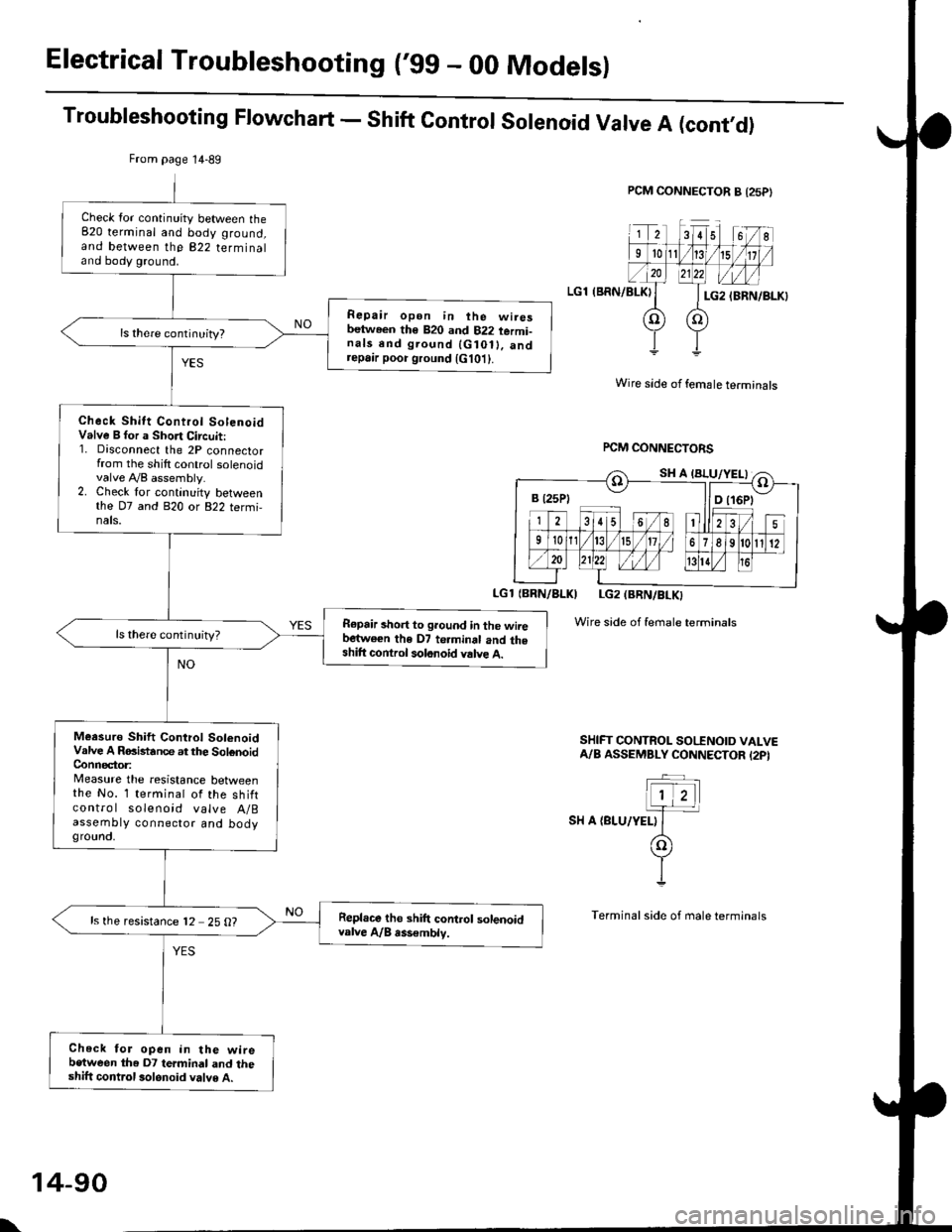
Troubleshooting Flowchart - Shift Control Solenoid Valve A (cont,O)
PCM CONNECTOR B {25P}
LGl (BRN/BLKI
Wire side of female terminals
rcM CONNECTORS
LGl {BBN/BLKI LG2 (BRN/BLKI
Wire side of female terminals
SHIFT CONTROL SO|'INOID VALVEA/B ASSEMBLY CONNECTOR I2PI
SH A {BLU/YELI
From page 14-89
Check lor continuity between the820 terminal and body ground,and between the 822 terminaland body ground.
Repair open in ihe wiresbetween th€ 820 and 822 termi-nals end ground {G10ll. andrepa,r poor ground {G101}.
Check Shitt Control SolenoidValve B for a Short Circuit:1. Disconnect the 2P connectorfrom the shilt control solenoidvalve A,/B assembly.2. Check lor continuity betweenthe D7 and 820 or 822 termi,nals.
R€pair short to ground in the wiiebartwe€n the D7 te.minal and theshift control solonoid valve A.
ls there continuity?
Meesuro Shift Control SolenoidValve A RGistance at the SolenoidConnector:Measure the resistance betweenthe No. 1 terminal of the shiftcontro I solenoid valve A/Bassembty connector and bodygrounct,
Repl.ce tho shift control solenoidvalve A/B rss€mblv.ls the resistance 12 25 O?
Check for open in the wirebetween the D7 termindl and theshift control 3olonoid valve A.
B t25Pt llD t16Pt
\
14-90
Page 770 of 2189

Electrical Troubleshoot:ng ('gg - 00 Models)
Troubleshooting Flowchart - Shift Control Solenoid Valve B (cont,dl
PCM CONNECTOR A {25PI
LGl (BRN/BLK)
IBRN/BLKI LG2IBRN/BLK)
Wire side of temale terminals
Wire sid€ ot female terminals
FCM CONNECTORS
SHIFT @NTROL SOENOID VALVEA/A ASSEMBLY CONNECTOR (2PI
.-_
1)2-.T-
I sn e tcanlwxrt
(o
YI
Terminal side oI male terminals
Check for continuity between the820 terminal and body ground,and between the 822 terminaland body ground.
Ropair opan in the wirgsb.twocn the 820 rnd 822 te.mi,n.ls and ground lG10t), and..p.ir poor ground lG10t).
Check Shift Control Sol.noidVrlve B tor a Short Ci.cuit:1. Disconnect the 2P connectorfrom the shift control solenoidvalve A/B assembly.2. Check for continuity betweenthe D2 and 820 or 822 termi-nals.
Repair 3hort to ground in tho wirebotw.en tha 02 torminsl and theshift com.ol rolonoid v.lv. B.
Meaiuro Shift Cont.ol SolonoidVrlve B Raailtrnca at the SolonoidConn€c,toa:Messure the r€sistance belweenthe No. 2 terminal of the 6hiftcontrol solenoid valve A/Bassembly connector and bodyground.
R.pl.co th. 3hift control lolenoidv!lv. A/8.lsombly.ls the resistance 12 - 25 O?
Chack for open in the wi.ebetwoon th€ D2 termin.l and the3hift control lolanoid valv6 8.
B (25P1 - llDt
From page'14-91
SH B (GRN/WHTI
\
14-92
Page 776 of 2189

Electrical Troubleshooting ('99 - 00 Modelsl
Troubleshooting Flowchart - Linear Solenoid (cont'dl
Check Linea. Solenoid tor aShort Ci.cuit:Check for continuity between thebody ground and the 88 terminaland B17 terminal individually.
PCM CONNECTOR A {25PI
Wire side of female terminals
From page 14 97
Repair shon in the wir6 betweenth€ 88 and 817 terminals and thelin€ar solenoid,
Measure Linear SolenoidResistance:1. Connect the linear solenoidconnector,2. Meas u re the resistancebetween the Bg and 817 termtnals,
Repair loose te.minal or open inthe wire botwoen the 88 .nd Bl7t.rmin.b end the linoar 3olenoid.
ls the resistance approx. 5.0 O?
Check for loose terminal tit in thePCM conn€ctors, lf necessary,substitut6 a known-good PCMand recheck.
LSAM (WHTI
14-98
Page 780 of 2189

Electrical Troubleshooting ('99 - 00 Models)
Troubleshooting Flowchart - E Indicator Light Does Not Come On
FCM CONNECTOR B (25P}
LGl {8RN/ALKI{BRN/8LK}
Wire side ol temale terminals
LGl IBNN/BLK} LG2 {BRN/BLK)
i2t5 6q
910t7
LG2
o) (o
The Pll indicator light does notcome on when the ignitionswitch is fi.st turned ON (ll). lltshould come on for about twoseconda.l
Check the Service Check Con-nector:Make sure the special tool (SCS
Service Connector) is not connect-ed to the service check connector?
ls the specialtool {SCS ServiceConnector) is not connected tothe seNice check connector.
Disconnect the special tool fromthe service check connector andr6check.
Check the Dll lndicator LightiShift to d position.
Check for loose terminal fit in thePCM connecto13. It necessary.sub3titute a known-good PCMand recheck.
Does the @ indicator lightcome on?
Check the Ground Circuit:1. Turn the ignition switch OFF.2. Disconnect the B (25P) con-nector from the PCM.3. Check for continuity betweenthe 820 terminal and bodyground, and between the 822terminal and body ground.
Repair open in the wiresbetween the B20 rnd 822 termi-nals and ground (G101), andrep.ir poor ground (G1011.
Measure Power Supply CircuitVoltage:1. Turn the ignition switch ON {ll}.2. Measure the voltage betweenterminals B1 and 822 andbetween terminals Bg and820.
Repair open or short in the wi.obetween th6 81 and/or 89 termi-nals and the PGM-FI main relav,and between th€ PGM-FI mainr€ley rnd the under-hood tus€/relay box.
To page 14''103
14-102
Page 871 of 2189

Continuously Variable Transmission (CVTI
Special Tools ................ 14-194
Description .................... 14-195
Clutches/Reverse Brake/Planetary
Gear/Pulleys .......... 14-198
power Flow ..............,..... 14-200
Electronic Control SYstem(,96 - 98 Modets) ......14-203
Electronic Control System
('99 - oo Models) " 14-205
Hydraulic Control '....... 14-208
Hydraulic Flow .'..-.....'... '14-212
Park Mechanism .....-...'.' 14-222
Eleqtrical Systom
Component Locations'96 - 98 Models """"""' 14-224,99 - 00 Modets ............. 14-225
TCM Circuit Diagram ('96 - 98 Models) ............. 14-226
TCM Terminal Voltage/Measuring Condiiions ('96 - 98 Models) '.... 14-228
PcM Circuit Oiaqram{A/T Control System: '99 - 00 Models} ...--.... 14-230
PCM Terminal Voltage/Measuring Conditions('99 - 00 Models)
A/4 Control System .'.'...14-232
Troubleshooting Procedures ... . .... .....',........."' '14-234
Symptom-to-ComPonent Chart
Electrical System - '96 - 98 Models ......'..... '14-234
Electrical System -'99 - 00 Models ..'....-..-. '11-210
Electrical Troubleshooting
Troubleshooting Flowcharts('96 - 98 Models) """'11-242
Troubleshooting Flowchart
('99 - 0O Modets) ...... 14-265
Linear Solenoids/lnhibitor Solenoid
Test ......................... . ...... 14-29f
Drive Pulley/Driven Pulley/Secondary Gear
Shaft Speed Sensors
Replacement .........'...... .14-292
Start Clutch Control
Start Clutch Calibration Procedure ....... ....,. 14-293
Hydraulic SYstem
Symptom-to-ComPonent Chart
Hydraulic System '.'.......14-294
Road Test ............................ 14-296
Stall Speed
Test......................... ...... 14-294
Fluid Level
Checking/Changing ....... 14-299
Pressure Testing ................. 14-300
Lower Valve BodY AssemblY
Replacement ..........,... 14-302
ATF Filter
Removal/lnstallation ..... 14-303
Transmission
Transmission
Removal ........... . 14-304
lllustrated Index
Transmission/Lower Valve BodY
Assembly ................. 14-308
Transmission Housing/Flywheel Housing ... 14-310
End Cover/f ntermediate Housing ..........'.'.... 14-312
Transmission Housing/Lower Valve Body Assembly
Removal ..........'.... .. " 14-314
Transmission Housing/Flywhesl Housing
Removal ................. ........ 1+316
End Cover/lntermediate Housing
14-318Removal .........,...............
Manual Valve Body
Disassembly/lnspection/Reassemblv .'.'.'..... 1 4-320
Forward Clutch
lltustrated Index ........................................ 14-321
Disassemblv .................. 14-322
Reassemblv , ,, . ',','......14-324
Secondary Gear Shaft
25 x 35 mm Thrust Shim Selection ..'.'....-... 14-324
Differential
lllustrated lndex ...,.....................,.,...-.-.-...'... 14-329
Backlash Inspection .-....14-329
Bearing Replacement ......'........'....'... ....'... 14-330
Differential Carrier Replacement ........'........ 14-330
Oil Seal Removal ........... 14-331
Oil Seal Installation/Side Clearance ....... . . 14-331
Flywheel Housing Input Shaft Oil Seal
Replacement .....,.... ...'.'.. 14-333
Transmission Housing Bearings
Driven Pulley Shaft Bearing
Replacenient ...................'. . ...................'.. 14-334
Secondary Gear Shaft Bearing
Reolacbment ...................... . .......... . ........ 14-335
Flywheel Housing Beating
Secondary Gear Shaft BearingReo1acement..................,........................... 14-335
Ring Gear Bearing
Replacement......... ........ 14-336
Control Shaft Assembly
Removal/lnstallation ....................'........... 14-336
Transmission
Reassembly .................. 14-338
Flywheel/Drive Plate .. . ...... . ...... ... . ....-.....'.'...14-341
Transmission
lnstalation ..................... 14-348
Cooler Flushing .'......... 14-352
shift cable
Removal/lnstallation....'........." """ 14-354
Adjustment .......'........ 14-355
Shift Lever ........................,. 14'356
Shift Indicator Panel
Adjustment ................ 14-357
ATF Cooler/Hoses
lnsta llation ......,,...... .... 14-357
Page 927 of 2189

Electrical Troubleshooting (,96 - 9g Modelsl
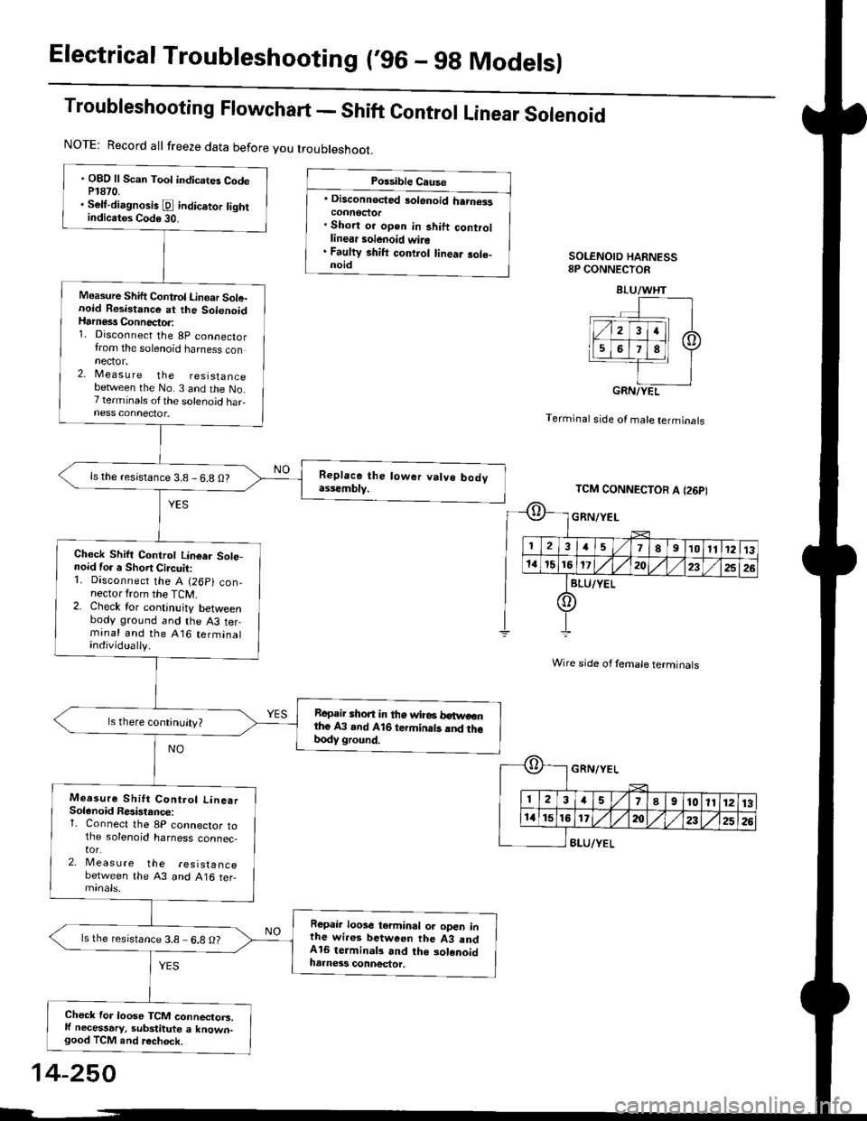
Troubleshooting Flowchart - Shift Control Linear Solenoid
Possible Cause
' Disconnected 3olenoid h.rn€isconnoctor. Short or open in 3hift controllinear solenoid wire. Faulty shift control linear sole-noidSOLENOID HARNESS8P CONNECTOR
Terminal stde of male terminals
Wire side of female terminals
8LU/YEL
NOTE: Record all freeze data before you troubleshoot.
. OBD ll Scan Toot indicates CodeP1870.. Selt-dirgnosis [d indic.tor tightindicatos Code 30.
Measure Shift Control Linoar Sole-noid Resistance at the SolenoidHarness Connector:1. Disconnect the 8p connectorfrom the solenoid harness connector.2, Measu re the resistancebetlveen the No. 3 and the No.7 terminals ofthe solenoid haFness connector.
ls the resistance 3.8 - 6.8 O?
Check Shift Controt Linear Sote-noid for a Short Circuit:1. Disconnect the A (26p) con,nector from the TCM.2. Check for continuity betweenbody ground and the A3 terminal and the A16 terminalindividually.
Repair shon in tho wire6 betweonthe A3 and A16 termin.ts lnd thobody ground.
Measure Shitt Control Line.rSolenoid Resistance:1. Connect the 8P connector tothe solenoid harness connec,tor.2, Meas u re the resistancebetween the 43 and A16 ter-
Repair loose terminal oa open inthe wires between the 43 andA16 terminal3 and the solenoidharness connector.
ls the resistance 3.8 6.8 O?
Chock for loose TCM connectorc.ll necessary, substitute a known-good TCM and recheck.
BLU/WHT
GRN/YEL
TCM CONNECTOR A I26PI
GRN/YEL
ll 12l:
IriGlx
1578910111213
172t)232526
14-250