1998 HONDA CIVIC Block bolt
[x] Cancel search: Block boltPage 791 of 2189
Road Test
NOTE: Warm up the engine to normal operating tem peratu re (the rad iator fan comes on )'
1. Apply parking brake and block the wheels. Start the engine, then shift to E position while depressing the brake
Dedal, Depress the accelerator pedal and release it suddenly. The engine should not stall'
2. Repeat same test in E Position.
3. Test-drive the vehicle on a flat road in the E position. Check that the shift points occur at approximate speeds shown
in the table. Also check for abnormal noise and clutch slippage.
NOTE: Throttle position sensor voltage represents the throttle opening
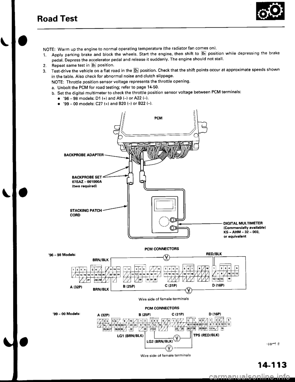
a. Unbolt the PCM for road testing; refer to page 14-50.
b. Setthedigital multimeter to check the th rottle position sensor voltage between PCM terminals;
. '96 - 98 models: D1 {+) and A9 (-) or 422 (-}.
. '99 - 00 models: C27 (+) andB20t-) orB22{-}.
BACKPROBE ADAPTER
BACKPROBE SET07sAz - 001oq)A{two requiredl
DIGIIAL MULTIMETERlCommercially available)KS-AHM-32-003,or equivalenl
'96 - 98 Modelsr
Wire side ol temale terminals
PCM CONNECTORS
B t25Pl c (31P)
LG1 IBRN/BLK)
I (25P1c (31P}
A t32PtD (16P)
Wire side ol female terminals
'9!t - 00 Models:
1+113
Page 979 of 2189

Lower Valve Body Assembly
Replacement
@ Make sure lifts, iacks, and saf€ty stands
are placsd prop€rly {sea section 1).
CAUTION: While removing and installing th6 lower
valve body asssmbly, b€ sule not to allow dust and
other for€ign particles to entsr inio the transmksion.
1. Raise the front of the vehicle, and support it with
safetv stands (see section 1).
2. Set the parking brake, and block both rear wheels
securetv.
4.
6.
Remove the drain plug, and drain the CVT fluid.
Reinstall the drain plug with a new sealing washer(see page 1+299).
CAUTION: Keop all of other toreign parliclos out of
the transmission.
Disconnect the 8P connector from the solenoid har-
ness connector.
Remove the ATF cooler hoses at the ATF cooler
lines. Turn the ends of the ATF cooler hoses up to
prevent ATF from flowing out, then plug the ATF
cooler noses.
CAUTION: Keep all of other foroign particlo3 out of
tho transmission.
Remove the right front mounvbracket.
10 x 1.25 mmila N.m (,1.5 kgf.m, 33 lbtft)
RIGHT FRONTMOUNT/BRACKET
ATF COOLER LINE
10 x 1.25 mmsil N.m 15.5 kgf.m,40 rbr.ft)
ATF COOLER HOSE
14-302
14.
7. Remove the ATF cooler outlet line.
8. Remove the ATF cooler line bracket bolt.
9. Remove the ATF pan (fourteen bolts).
10. Remove the ATF strainer (two bolts).
1 l. Remove the one bolt securing the solenoid harness
connector,
12. Remove the
bolts).
lower valve body assembly (eight
LINE BOLT28 N.m (2.9 kgtm,21 lbtft)SEALINGReplace.
ATF COOI.-EROUTLET
OOWEL PIN
O.RINGFeplace.
SOLENOIO HARNESSCONNECTOR
5x1.0mm12 N.m 11.2 kgt.m,8.7 tbt.ftlO.RINGReplace.ATFSTNAINER
6x1.0mm12 N.m 11.2 kgt m,E.7 tbt'ft)
OOWEL NN
BODY ASSEMBLY
6x1.0mm12 N.m 11.2 kgf.m,8.7 rbf.ft)
ATF PAN GASKETReplace.
VALVE
ATF COOLER INLETUNE BRACKET BOLT8 x 1,25 mm26 N.m {2.7 kgf.m,20 tbf.frl
13.
ATF PANx 1.0 mm12 N.m 11.2 kgf.m, E.7 lbf.ftl
Install the new lower valve bodv in the reverse
ordgr of the removal orocedure.
CAUTION: Koep all ot other fo.oign particles out of
ths transmission.
NOTE:
. Replace the following parts:
- O-rings on the solenoid harness connector
and the ATF strainer- ATF pan gasket- Sealing washers
. lf the ATF cooler inlet line bracket is bent or
warped, put it back to the original position.
Perform the start clutch calibration orocedure on
page 14-293.
Page 980 of 2189

ATF Filter
l.Removal/lnstallation
!@ Make sure lifts, lEcks, snd safoty stands
ara pl8ced properly {sae section 1).
CAUTION: While removing and installing the ATF tilier,
be sure not to allow dust or other for6ign particle3 to
enter thg transmission.
1. Raise the front of the vehicle, and support it with
safety stands (see section 1).
2. Set the parking brake, and block both rear wheels
securely.
3. Remove the drain plug, and drain the CVT fluid.
Reinstall the drain plug with a new sealing washer
{see page 14-299).
fl,
5.
CAUTION: Keep all toreign particles out ot the
transmission.
Remove the ATF cooler hoses at the ATF cooler
lines. Turn the ends of the ATF cooler hoses up to
prevent ATF from flowing out, then plug the ATF
cooler noses.
CAUTION: Keep all foreign particles out of the
transmission.
Remove the right front mounvbracket.
10 x 1.25 mm4{ N.m {i1.5 kgf.m,33 lbf ft)
ATF COOLER LINE
10 x 1.25 mm54 N.m {5.5 kgt'm,
40 rbl.ft)
ATF COOLER HOSE(|'t
14-303
6. Remove the ATF cooler outlet line.
7. Remove the ATF cooler line bracket bolt.
8. Remove the ATF pan (fourteen bolts)
9. Remove the ATF cooler inlet line from the ATF pan
(three bolts).
10. Remove the ATF filter, and clean it.
11. Check that the ATF filter is in good condition.
12. Replace the ATF filter if it is clogged.
LINE BOLT28 N.m {2.9 kgf.m,21 lbt.ft)
ATF COO1TR OUTIET
6x1.0mm
ATF COOLER INI-ETLINE ERACKET BOLT8 x 1.25 mm26 N.m (2.7 kgt.m,20 rbtftt
O.RINGReplace.
ATF
ATF FILTER
ATF PAN
6x1.0mm12 N.m (1.2 kgt'm,8.7 lbl'ft)
lnstall the ATF filter in the reverse order of the
removal procedure.
GAUTION: Keep all foreign particles out ot the
transmission,
NOTE:
Replace the O-rings, the ATF pan gasket and
sealing washers.
lf the ATF cooler inlet line bracket is bent or
warped. put it back to the original position
GASKETReplace.
'13.
12 N m (1.2 kgf m,
Page 1006 of 2189
Differential
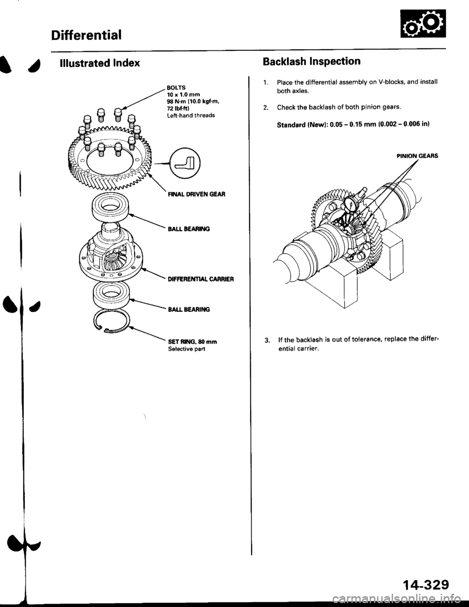
l.lllustrated Index
BOLTS10 x 1.0 mm98 N.m 110.0 kgf.m,72 tbl.ltlLeft-hand threads
FII{AL ORIVEN GEAR
BAIT EEANIM;
SET RING. 8() tnmSoloctivo pan
Bacl(lash Inspection
1. Place the differential assembly on V-blocks, and install
both axles.
2. Check the backlash of both pinion gears.
Standard (Newl: 0.05 - 0.15 mm 10.002 - 0.006 in)
PINION GEARS
lf the backlash is out of tolerance, replace the differ-
ential carrier.
14-329
Page 1167 of 2189
Front Brake Caliper
It
Disassembly
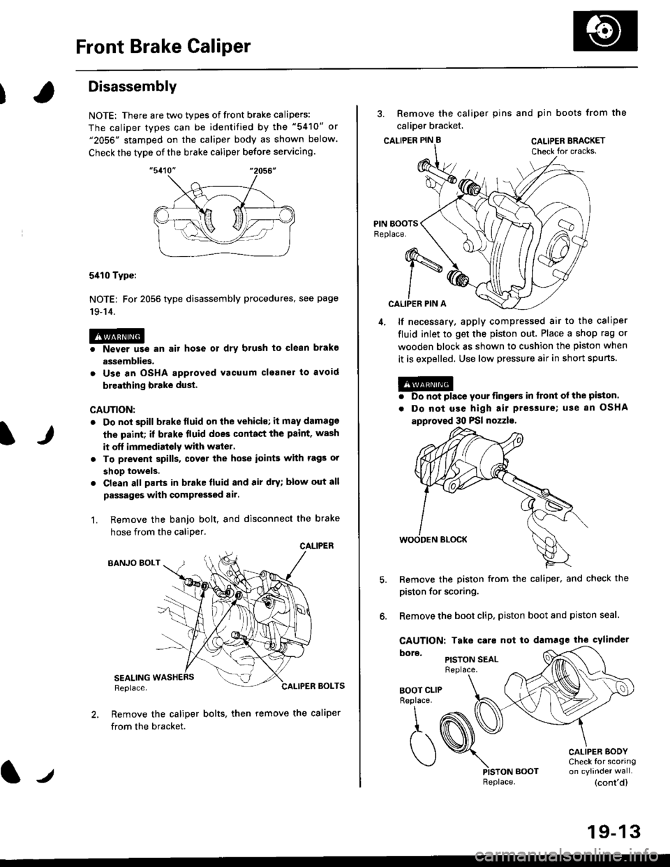
NOTE: There are two types of front brake calipers:
The caliper types can be identified by the "5410" or"2056" stamped on the caliper body as shown below.
Check the type of the brake caliper before servicing.
5410 Type:
NOTE: For 2056 type disassembly procedures, see page
19-14.
@o Never use an air hose ot dry brush to clean brakg
assemblies.
. Use an OSHA approved vacuum clganer to avoid
breathing brake dust.
CAUTION:
. Do not spill brake lluid on the vehicls; it may damage
the paint; if brake fluid does conlact the paint, wash
it off immedistely with waier.
. To prevenl spills, covet the hose ioin$ with rags or
shop towels.
. Clean all parts in brake fluid and air dry; blow out all
passages with compressed air.
L Remove the banjo bolt, and disconnect the brake
hose from the caliDer.
CALIPER
BANJO EOLT
SEALINGReplace.BOLTS
Remove the caliper bolts, then remove the caliper
from the bracket.
lJReplace.
3. Remove the caliper pins and pin boots from the
calioer bracket,
CALTPER PIN B CAL|PER BRACKET
CALIPER PIN A
4, lf necessary. apply compressed air to the caliper
fluid inlet to get the piston out. Place a shop rag or
wooden block as shown to cushion the piston when
it is expelled. Use low pressure air in short spurts.
@. Do not place your iingers in tront ol the piston.
. Do not use high air pressure; use 8n OSHA
approved 30 PSI nozzls,
Remove the piston from the caliper, and check the
piston for scoring.
Remove the boot clip, piston boot and piston seal.
CAUTION: Take care not to damage the cylindcr
PISTON SEALReplace.
BOOT CLIPReplace.
\,
,t. (
)PISTON BOOT
CALIPER BODYCheck for scoring
(cont'd)
19-13
Page 1168 of 2189
Front Brake Caliper
2056 Type:
@
Disassembly (cont'dl
Nevor u3e an air hos€ or dry brush to clgan brake
assomblios.
Use an OSHA approved vacuum cl6aner to avoid
braathing braks duet.
CAUTION:
. Do not spill brakefluid on ths vchicle; it may damage
the paint; if brako fluid does contact the p.int. wash
it olt immediately with wato..
. To prevsnt spills, cover the ho3o ioints whh rag3 or
shop towels.
. Cl€an all parts in brake fluid and air dry; blow out 8ll
passagss with compr63€d air.
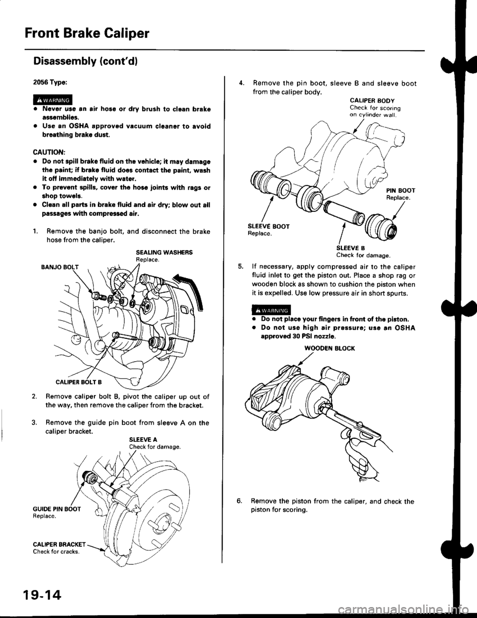
1. Remove the banjo bolt, and disconnect the brake
hose from the caliper.
SEALING WASHERS
Remove caliper bolt B, pivot the caliper up out of
the way, then remove the caliper from the bracket.
Remove the guide pin boot from sleeve A on the
caliDer bracket.
GUIDE PIN BOOTReplace.
GALIPER BRACKETCheck tor cracks.
Check for damage.
19-14
4. Remove the pin boot, sleeve B and sleeve boot
from the caliper body.
CALIPER EODYCheck for scoringon cytinder wa .
SLEEV€ BCheck for damage.
lf necessary, apply compressed air to the csliper
fluid inlet to get the piston out. Place a shop rag or
wooden block as shown to cushion the oiston when
it is expelled. Use low pressure air in short spurts,
a
a
Do not placo your lingers in ftont ol tho pkton.
Do noi usa high air prsssure; uso an OSHA
approved 30 PSI nozzle.
Remove the piston from the caliper, and check thepiston for scoring.
WOODEN ALOCK
Page 1178 of 2189
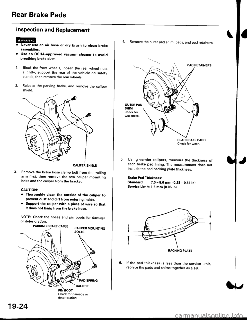
Rear Brake Pads
Inspection and Replacement
Never use an air hose or dry brush to clean brakeassemblies.
Use an OsHA-apptoved vacuum cl€aner to avoidbreathing brake dust,
Block the front wheels, loosen the rear wneet nutsslightly, support the rear of the vehicle on safetystands, then remove the rear wheels.
Release the parking brake, and remove the calioersh ield.
CALIPER SHIELD
Remove the brake hose clamp bolt from the trailingarm first, then remove the two caliper mountingbolts and the caliper from the bracket.
CAUTION:
. Thoroughly clean the outside of the caliDer toprevent dust and dirt trom entering inside.. Support the calipor with a pieco of wire so thatit does not hang fuom the brake hose.
NOTEr Check the hoses and pin boots for damageor deterioration.
PARKING BRAKE CABLE ^.. ._-_ ---.
'L
19-24
4. Remove the outer pad shim, pads, and pad retainers.
PAO RETAINERS
OUTER PAOSHIMCheck for
REAR BRAKE PADSCheck for wear.
Using vernier calipers, measure the thickness ofeach brake pad lining. The measurement does notanclude the pad backing plate thickness.
Brake Pad Thickness:
Standard: 7.0 - 8.0 mm {0.28 - 0.31 in}Service Limit: 1.5 mm {0.06 in}
lf the pad thickness is less than the service limit,replace the pads and shims together as a set.
BACKING PI-ATE
Page 1189 of 2189
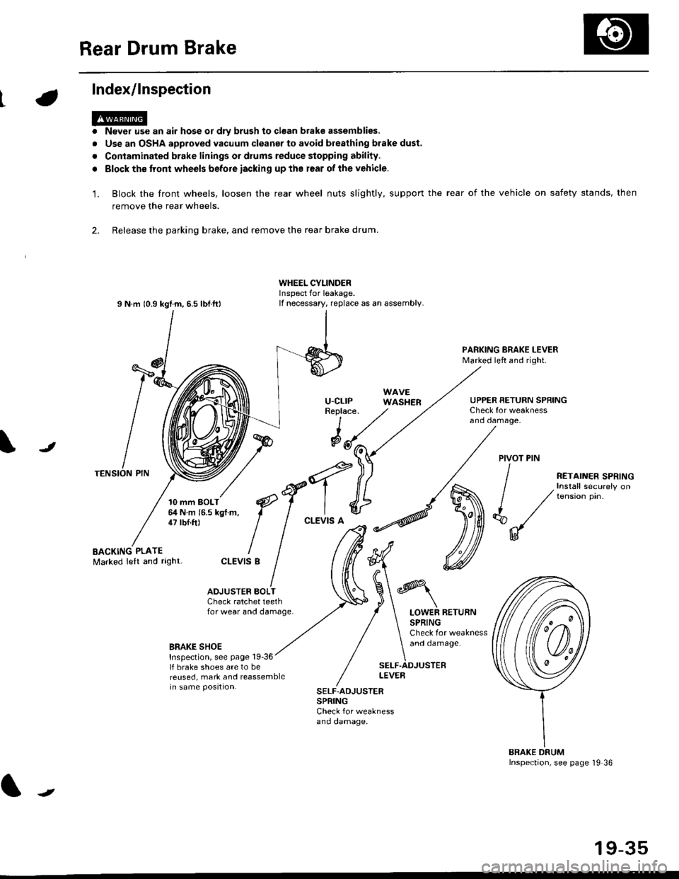
Rear Drum Brake
Index/lnspection
'1.
a
a
Never use an air hose or dly brush to clean brake assemblies,
Use an OSHA approved vacuum cleanar to avoid breathing brake dust,
Contaminated brake linings or drums reduce stopping ability.
Block the tront wheels before iacking up ths r€ar of lhe vehicle.
Block the front wheels, loosen the rear wheel nuts slightly, support the rear of the vehicle on safety stands, then
remove the rear wheels.
2. Release the parking brake, and remove the rear brake drum.
I N m 10.9 kgtm, 6.5 lbf.ftl
TENSION PIN
10 mm BOLT6,1N m 15.5 kgf m,47 tbf.ft)
WHEEL CYLINDERInspect for leakage.lf necessary, replace as an assembly.
u-cLrPReplace.
WAVEWASHER
PARKING BRAKE LEVERMarked left and right.
Check for weaknessano oamage,
UPPER RETURN SPRING
I
@JPIVOT PIN
BACKING PLATEMarked lelt and right-
/
€f-l.^
I I
*'t")
ctEv'sB
/ (t
/ ,.ro,".r r.*,"n
/ , Install securely on
| / tension pin.
d"/
IU
ADJUSTER BOI-TCheck ratchet teethfor wear and damage.LOWER RETURNSPRINGCheck for weaknessand oamage.BRAKE SHOEInspection, see page 19-36lf brake shoes are to bereused, mark and reassemblein same position.
SELF.ADJUSTERLEVEB
SELF-ADJUSTERSPRINGCheck for weaknessano oamage.
BRAKE DRUMInspection, see page '19 36
t
19-35