Page 1853 of 2189
* = '96-98 models except D1685,'99100 D16Y5 with lVl/T
UNDER-HOODFUSE/RELAYBOX
'98CW - -.
, r--1
:ll:,tt:
: r--J ;, TRANSMISSION ,. CONTROL' MODULE OCM) :' Page 3g-4 ;I PHOIO 121I vlEW 69
I
I
\FUS€ 47aAcx uP
c351
WHT/BLIJ
WHT/BLU
WHT/BLU
18c4'l t
vlEw 60
WHT/ALU
WHT/ALU
11c440
WHT/BLU
10
' WHT/BLU
, 423
c131
vtEw 59
WHT/BITJ
'96-'98
models
I
tl
tl
STEREORADIOTUNERPage 150
'99-'m
modelsmodeB
'99-'�00
models
c723c723
vtEw 57
wHr/atu
810B�21cc10)
tl
ll
HEATERCONTROLPANELPages 60-1,61-2,62-2,and 63-2
vtEw 76
tl
tl
POWERTRAIN oTENGINE CONTROLMODULE(PCM or ECM)
Page 23, 24, ot 25
AUDIOUNITPage 150
tl
HEATERCONTROLPANELPages 62-1and 63'1
10-1 1
Page 1858 of 2189
----" A/T -----t
DRIVEN PULLEY , ^.,.
;iftTBilis'".f l5Ftr,.""_
co'rinienixnn '. Pase 23'2
SPEED SENSOR ; .'-\.SHIELD 'F--.1
TDC/CKP/CYPSENSORSHIELDPage 20
ll
r_:.-i
23-13
t1
23- l4
tl
PRIMARY SECONDARYHO2S HO2SSHIELD SHIELDPages 23-8, Pages 23-9,23-10. and 23-11. and
--- CW ----.
TRANSMISSION ;CONTROLMODULE(TCM) ,Page 39-5 :PHO|O 121vlEw 69r____1 ,
tt:
tt:L----J,
. D16Y8engine
SECONDARY .
HO2S :SHIELD ;Page 23-11
l. - -..1 ;
tt:(D16Y/i D15Y8)Page 39-1
l.--.1
1l
r:--iBFN/BLKARN/BLK
A4
6FN/BLK' EFN/BI
i i srco"oo"t :' I GEAR SHAFT
I I Or MAtN!'tAt I. II SPEED SENSOR '
CW. - D16Y8 -, engine: N SENSoR SHTELD ,
i !i?il3li*u,, i
CWSHIELD :Page39-4,
CRANK-SHAFTSPEEDFLUCTU-ATION(cKF)SENSORPage 23-2
tl
ll
;I;..
26
i xNocx' SENSOR, (KS)' SHIELD
, Fage zJ-5
: F--.1
:ll
iilr-:i
----:.--------:
c442(Terminals 18-20)
c10.1 PHofo 125\HOTO 21 VIEW 54vtEw 29
'----- cw ----'
DRIVE
BFN/BLK
PULLEY :SPEEDSENSORSHIELDPage 39-4 :
1.---{ :I t;
cl30Oermlnal8'l-10)
vtEw 52
14-'�,
Page 1875 of 2189

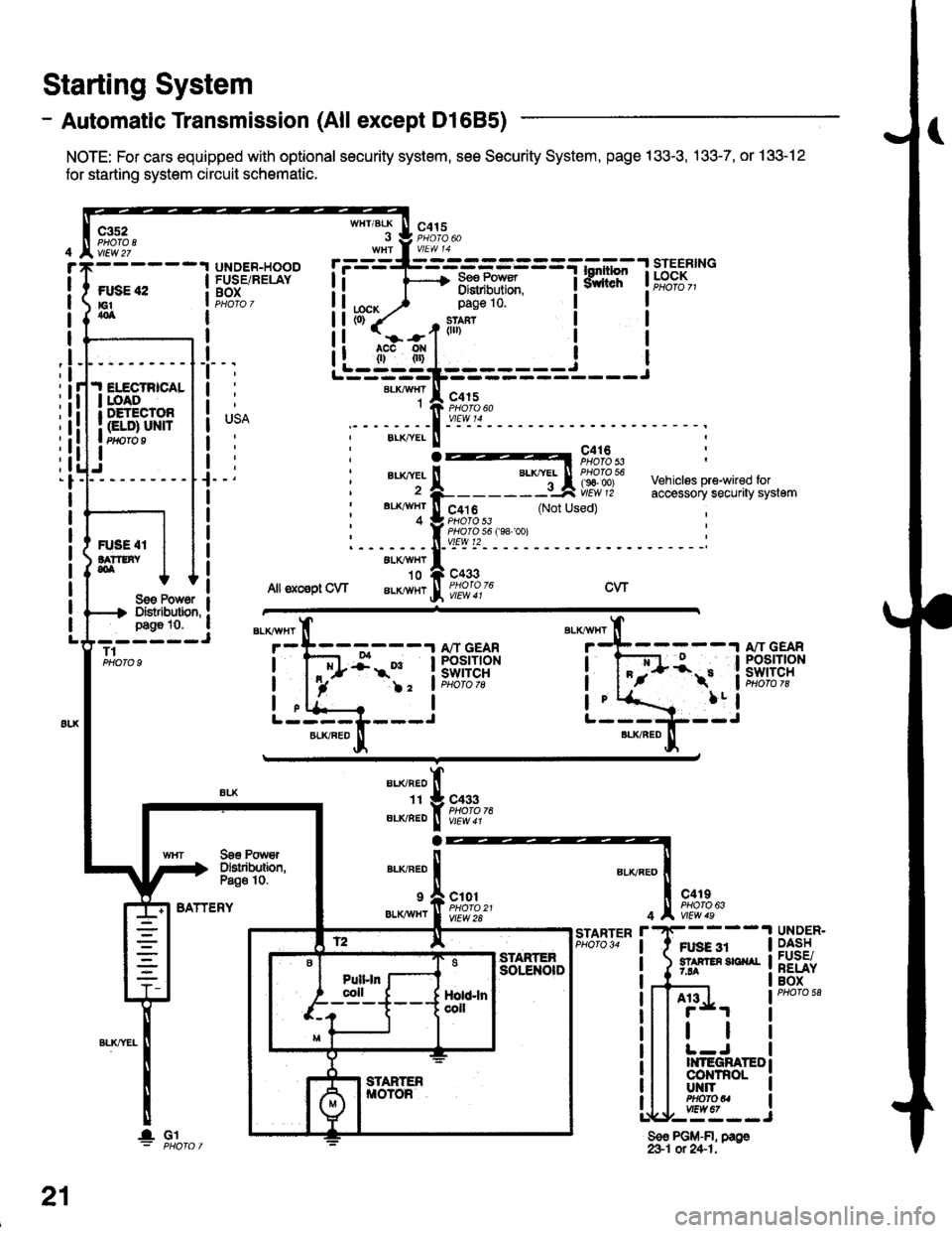
- Automatic Transmission (All except Dl685)
NOTE: For cars equipped with optional security system, see Security System, page 133-3, .133-7, or 133-12
for starting system circuit schomatic.
Starting System
c3s2PHO|O IvlEw 27
ftxiE "2E1404
WHT/BLK
I
lta":
c415
=-mF,Uf.
--l
9,lLT i ld;f,,"-
I
I
It
I
I
I
I
I
I
I
I
pag€ 10.
slan?(ll)
c415
I
Ji.I ELECTRICALI roAoI DETECTOR
I Gt ol ulra Ptfifo I
IJ
BLKAIVHT1
ELK./YEL
au(|vEL
BL'(4I/HT
4
c416PHOTO 53
c4t 6PHO|O 53PHO|O 56 f98 '�oo)vtEw t2
c433
Vehiclss pre-wired foraccessory securaty system(Not Used)
R'SE 4IlA??tNY,olALXAVHY'10
Allsxcsptow aLKlvHrcwSoe Pow6r IDistibution, !page 10. a- ----JT1PHOTO 9
BATTERY
BLKAVHT
7
L-----L---JBLKFED
13:;-1ifl;ft?R
!-
)2 'lPHoto tg
a
BLI(RED
1I
ELIVBED
ALKNED
c433PHOTO 76
Soe PowrDslributbn,Pa€o 10.
9 a c101
er.xiwxr I ffo,rtfl'�t
c4rIPHO|O 63
Ft gg 3r5? F En 3E ^r7.94
4
r'STARTERPHO|O 34UNDER.DASHFUSE/RELAYBOX
A13
tl
II{TEGRATEDco|{TnoLUT{ITPHOfOUvtEw 67,--==--J
Sso PGM-FI, page&1 ot 24-1.
21
lGl
Page 1876 of 2189
- Automatic Transmission (D1685)
c352
vtEw27
FUSE 42tGtao
.I ELECTRICALI LOADr DETECIOn
| (ELD) uNtrI PHOTO 9
I
UNDER.HOOOFUSE/RELAYBOX
r=-----L-_-_-_-_-_-=_-_-Tl.*1"","1#"Ei]""
li F 3,"j,[',ul
WHT/BLK
. J 9,1'3.WHt a V|EW 14
tcx,^ ) Page 10'
PHOTO 76
1--*---''!N"t- \o3bz7
See PowerDistribution,page 10.
c433
ALKRED4
r-^==.1
Stadorcontrol
POWERTRAINCONTROLMODULE (PCM)
c101
vtEw 28
ll
"'{----1iLi.' | |
Li-gl{l======i---i
"i*-iIr-m'
:il
See PowerDistribdion,Page '10.
".u,"if---'
-,*! s#;:{"
BLKAVHT N V/EW a t
STARTERCUTFELAYPHO|O 129
(99100)
A"/T GEARPOStTtONswrTcH
See PGlr-Fl,page 25.
STARTER
c419
FUSE 31STAffER Src{AI7.54
UNDER-DASHFUSE/NELAYBOX
BLKREO
11
"'-";;tr
A't 3
BATTERY
21-1
Page 1877 of 2189

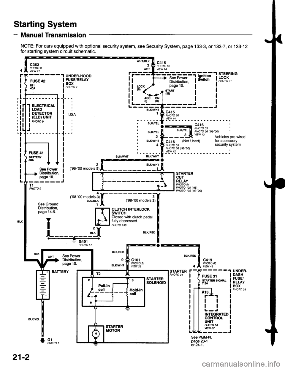
- Manual Transmission
NOTE: For cars equipped with optional security system, see Security System, page 133-3, or 133-7, or 133-12
for starting system circuit schematic.
Starting System
c3s2PHOTA 8vtEw 27
WHT/BLKc415
FUSE 42to!a0a
UNDER-HOODFUSE/RELAYBOXI
I
I
_l
IELECTBICALIOADDETECTOR(ELO) UN|TPtloro I
Sae Po'/Y€rDislibution,pag€ 10.------JT1
Se6 GroundDislribution,page 14-6.
BATTERY
STARTERCUTRELAY
PHO|A 129198)PllO|O r35 f99 00)
a
BLK/FED
9
BLKAVHT
ct01
vlEW 2A
c4't9
vtEw 49
FUSE 31STAATER SICIIAL7.5A
STARTER
4
Sse PGM-FI,page 231ot 2+1.
UNDER-DASHFUSE/RELAYBOX
At3
tl
tl
INTEGRATEDcol{tRoLut{llPHO|O U
r.------T-------------=;-*^:-lsrEERtNG
I i 1'----> R*.|?xf: iiiliffi' t"t%?I,,I Distribulion.1j;cx y' page 10.(0)
it-jtr'tl i
j
r---_-_€rx^,:jF;f
;-;:.==:t A r,+lo'tii:,J?"""
;--;*;.-f -- ^.:---.---1--
,'rr-'OO .o0"," 3,rffiEj,
---;;;;i[
cLUrcH TNTERLOCK tClosed wrlh clutch pedal Ifully depressed. llPHoro 1ra I"**"
!
Se€ PowerDistibution,page 10.
4('98100 models 3)ALU/BLK
f2 lE--r.---?q_l srAFrEn
21-2
I- G1
Page 1886 of 2189
PGM-FI (All '9G'98 Models except Dl685; '99r0O D16y5 with M/T)
TRANSMISSIONCONTROLMODULE (TCM)
llEv/ 69
ECM ECMcontrol controlReference data datavollage inDutNREF) OMA}:q{.J
(VREF) OMA) OMB)Reference ECM ECMcontroldatajnput
EGRcontrol shift' I solenoid
i
-l
"""'"x :i1",'
sofenoid lock Pa(klvave Circult neutr; I vave circuit neutral| | control control inPut, ! (EsOLr {sru, (A}FNP):L------
voltag€ controldataoutput
I
{
ta
i;;;;';;
."
*
'i\,
' circuit neutral Reverse D4 D3 2 indtcator, ;' control input input input input input control | -,| (sLU) rAlPNPr TATPFI {ATpO4i dlPD3) tAfPzr rDa rNDl | /
[J=:ITTIT'{t
' Interlock See Automatrc: Svstem Transmission Controls I
i i controt
i
"'J;:;;,.,"^,
!
l1l
"lL
:1,.
i
".f:;;,.,"^, 1.,."n,
: I lt ti.."stEBkTJBi ""il*l"*
: | /" I SOLENOTD VALVE
i \J PHaro 12a I
i
t'i!",,,
Bi"ifit**1
';
i l ;;;a ',, pase 14 !'#$tl ii{"Ff*,
i
*-1.
---f !.gg1mr..
' 4 cror| - PHAfO 123
23-6
Page 1922 of 2189

Gruise Control (cont'd)
- How the Circuit Works
The cruise control system uses mechanical and
electrical devices to maintain the car's sDeed at a
setting selected by the driver.
System Description
The cruise control unit receives command signals
from the crurse control main switch and the cruise
control SeVResume switch. With the ignition switch
in ON (ll) or START (lll), voltage is provided to the
cruise control main switch through fuse 14. When
you push the switch to ON, power is provided to the
cruise control unit and the brake switch.
The cruise control unit receives information about
operating conditions from the brake switch, the
vehicle speed sensor (VSS), and the clutch switch
(manual transmission) or the A,/T gear position
switch (automatic transmission). The cruise control
unit then sends signals to the cruise control actuator
which regulates the throttle position to maintain the
selected speed. The conlrol unit compares the
actual speed of the car to the selected speed. The
control unit then uses the result of that comoarison
to open or close the throttle.
The brake switch releases the system's control of
the throttle at the instant you press on the brake
pedal. The switch sends a signal to the control unit
by removing power from the normally closed brake
input (GRY wire), and providing power at the
normally open brake input (GRN/vVHT wire). The
control unit responds by allowing the throttle to
close. The clutch switch or the A,/T gear position
switch sends a "disengage" signal to the control unit
that also allows the throttle to close.
The cruise control system will set and automatically
maintain any speed above 25 mph (40 km/h). To set
it, make sure the main switch is on and the switch
indicator is on. Then, after reaching the desired
speed, press the SET switch. This sends a "set"
signal to the cruise control unit which, in turn,
controls the cruise control actuator to maintain the
set speed.
When you push the SET switch and the cruise
control system is on, the "cruise control" ON
indicator lights up.
34-4
(
You can cancel the cruise control system by
turning the main switch off . This removes power to
the control unit and erases the set speed from
memory. lf the system is disengaged temporarily
by the brake switch, or clutch switch, and the car's
speed is still above 25 mph, press the resume
switch: the car will automatically return to the
previously set speed.
For gradual acceleration without pressing the
accelerator pedal, push the RESUME switch and
hold it there. This will send an "acceleration" signal
to the control unit. When you release the switch, the
system will be reprogrammed for the new speed. To
slow the car down. oush the SET switch in and hold
it there. This sends a "deceleration" signal to the
control unit, causing the car to coast. When the
desired speed is reached, release the SET switch.
This reprograms the system tor the new speed.
Refer to the Service Manual (Section 23, Electrical)
tor specific tests or troubleshooting procedures.
(
a
Page 1930 of 2189
.I TRANSMISSION
I pa*l lcoNrRoLa noutral Reverso Driv€ inputs iMODULEI noutral Revelse lJriv€ inputi I MUuuLl-lilll'
! tarp pr) (aTpF) (Arp D) (ar" s) {ArP L) : Ploro^ t2'
;F"''^'*J l *l*|
.l
i{*m' vlEw 71
I
ll
,l
iatr=im*:l lJ l_L! !J
_____r| AJT G6ar
trJnl_
)a
\lseem l- caa,
I- Position
I I rrxrcaror
ll
tt
tlI .+----
3--{-----r----
" -T,[ i::I
"-1fi-*fiar+-!d
IFEOBII(BLU
r2A' ___ 14,{ ____134 _____Z_e______6i ____15"c_fJ^--oinir.-lf
i#fl''ucnNAVl{I ll GBN I GRN/REo ll GBN/ORN ll GBN/BLU lt GFNT'EL N rrtw.r,
{":-t{-8, 't'
I POSTTTONi swrTcHa PHO|O 78
r - - t- -- - - f -- - - - ? = - : - - - f - - - - -- r - - - - T - -t A,T GEaR
I
IJ