Page 1438 of 2189
![HONDA CIVIC 1998 6.G Workshop Manual Troubleshooting
Compressor lcontdl
COMPRESSOR CLUTCH RELAY4P SOCKET
l--;l
12 |---r--]l.l3 |L-J--J
] BLK/YEL
A(v)
!
ECM/PCM CONNECTOR A I32P}
Wire side of female terminats
*Howto use the backprobe set HONDA CIVIC 1998 6.G Workshop Manual Troubleshooting
Compressor lcontdl
COMPRESSOR CLUTCH RELAY4P SOCKET
l--;l
12 |---r--]l.l3 |L-J--J
] BLK/YEL
A(v)
!
ECM/PCM CONNECTOR A I32P}
Wire side of female terminats
*Howto use the backprobe set](/manual-img/13/6068/w960_6068-1437.png)
Troubleshooting
Compressor lcont'dl
COMPRESSOR CLUTCH RELAY4P SOCKET
l--;l
12 |---r--]l.l3 |L-J--J
] BLK/YEL
A(v)
!
ECM/PCM CONNECTOR A I32P}
Wire side of female terminats
*Howto use the backprobe setsConnect the backprobe adapters to the stackang patch cords, andconnect the cords to a multimeter. Using the wire insulation as aguide for the contoured tip of the backprobe adapter, gently slidethe tip into the connector from the wire side until it comes in con-tact with the terminalend ofthe wire (see section 11).
Frcm page 22-12
To page 22-15
Check Ior an open in the wire;1. Disconnecl the jumper wire.2. Turn the ignition swatch ON (ll).
3. l\4easure the voltage betweenthe No. 4 terminal of the com-pressor clutch relay 4P socketand body ground.
Repair open in the wire betw€enthe No. 17 fuso and the compres-sor clutch relav.
Check for an open in the wira:1. Turn the ignition switch OFF,then reinstall the compressorclutch relay.2. Make sure the A/C switch isOFF, then turn the ignitionswitch ON (ll).
3. Using a *Backprobe Set (T/N07SAZ 0010004), measurethe voltage between the No.17 terminal oI the ECM/PCMconnector A (32P) and bodyground with the ECM/PCMconnectors connected.
Repair open in the wirc betweonthe compressor clutch relay andthe ECM/PCtvt.
ls there battery voltage?
Page 1442 of 2189
Troubleshooting
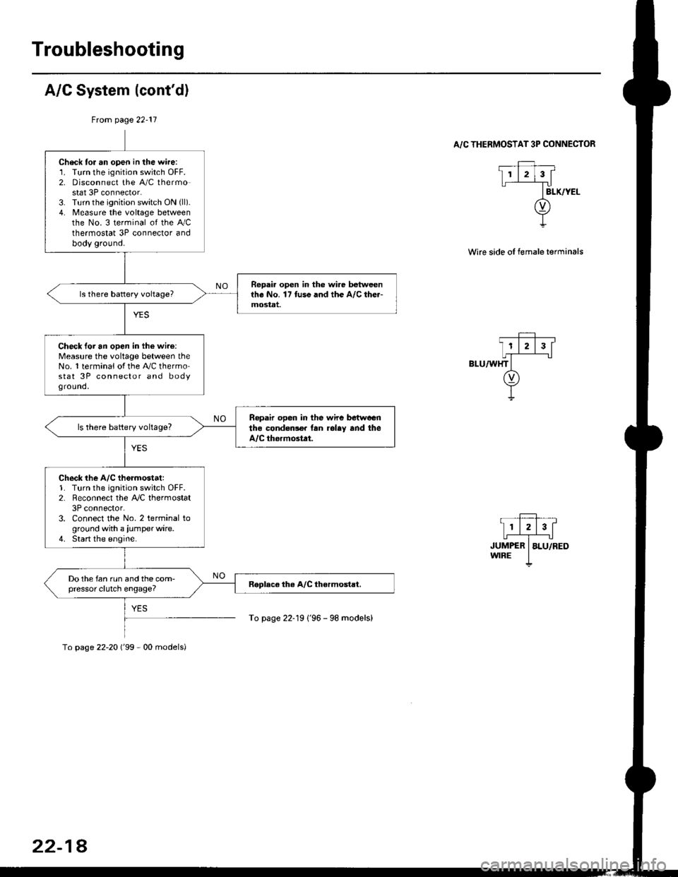
A/C System (cont'd)
From page 22-11
. _Ff,, __
I11213[
,r,il*"-T",-.r-'..owrRE I
To page 22-19 1'96 - 98 models)
A/C THERMOSTAT 3P CONNECTOR
Wire side oI female terminals
Check tor an open in the wire:1. Turn the ignition switch OFF.2. Disconnect the A/C thermostat 3P connector.3. Turn the ignition switch ON (ll).
4. Measure the voltage betweenthe No. 3 terminal of the Ay'Cthermostat 3P connector andbody ground.
Repai. open in the wire betweentho No. 17 tuso and the A/C the.-mostat.
Check loi an open in the wi.e:Measure the voltage between theNo. 1 terminal of the A,/C thermostat 3P connector and bodyground,
Ropair open in the wire betwoenthe condedlo. lan rolay and theA/C thormostat.
ls there battery voltage?
Check the A/C th6rmostat:1. Turn the ignition switch OFF.2. Reconnect the A,/C thermostat3P connector.3. Connect the No. 2 terminal toground with a iumperwire.4. Start the engine.
Do the fan run and the com-pressor clutch engage?
To page 22-20 ('99 - 00 models)
22-18
Page 1445 of 2189
A/C ThermostatRelays
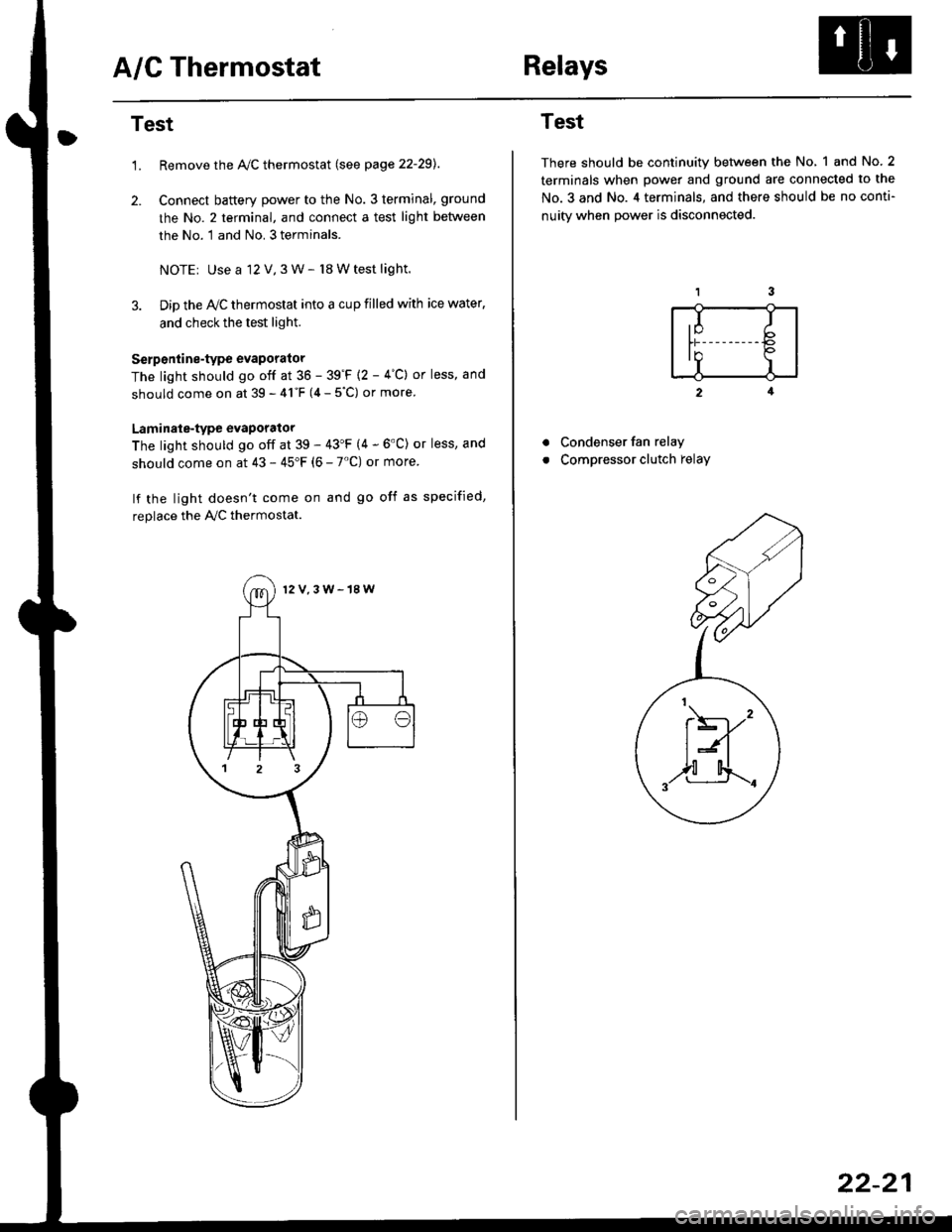
Test
1.Remove the Ay'C thermostat (see page 22-29).
Connect baftery power to the No. 3 terminal, ground
the No. 2 terminal, and connect a test light between
the No. 1 and No. 3 terminals.
NOTEr Use a 12 V,3 W- l8 W test light.
Dip the IVC thermostat into a cup filled with ice water,
and check the test light.
Serp6ntine-type evaporator
The light should go off at 36 - 39'F {2 - 4"C} or less, and
should come on at 39 - 41"F (4 - 5"C) or more
Laminale-type evaporator
The light should go off at 39 - 43'F (4 - 6'C) or less, and
should come on at 43 - 45"F (6 - 7'C) or more
lf the light doesn't come on and go off as specified,
replace the PVC thermostat.
12V,3W-18W
Test
There should be continuity between the No, 1 and No.2
terminals when power and ground are connected to the
No.3 and No. 4 terminals, and there should be no conti-
nuitv when Dower is disconnected.
2
Condenser fan relay
Compressor clutch relay
a
a
,I Ib
In Io'r I
t\----,'
t:n
,,l[4..-.
22-21
Page 1450 of 2189
A/C System Service
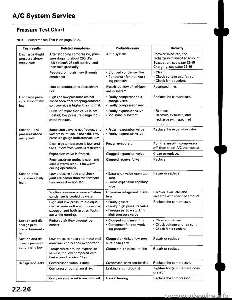
Pressure Test Chart
NOTE: Performance Test is on page 22-24,
Test resultsRelated symptomsProbabl€ causeRemedy
Discharge (high)
pressure aDnor-
mally high
After stopping compressor. pres-
sure drops to about 200 kPa
{2.0 kgflcm,,28 psi) quickly, and
then falls gradually.
Air in systemRecover, evacuate, and
recharge with specified amount.
Evacuation: see page 22-45
Charging: see page 22-46
Reduced or no air flow through
condenser
. Clogged condenser fins. Condenser fan not work-
ing properly
Clean.
Check voltage and fan rpm.
Check fan direction.
Line to condenser is excessively
hot.
Restricted flow of refriger-
ant in system
Restricted lines
Discharge pres-
sure abnormally
High and low pressures are bal-
anced soon after stopping compres-
sor, Low side is higher than normal.
. Faulty compressor dis-
charge valve. Faulty compressor seal
Replace the compressor.
Outlet of expansion valve is not
frosted, low pressure gauge indi-
cales vacuum.
. Faulty expansion valve. Moisture in system
. Replace,. Recover, evacuate, and
recharge with specified
amount.
Suction (low)
pressure abnor-
mally low
Expansion valve is not frosted, and
low oressure line is not cold. Low
pressure gauge indicates vacuum.
. Frozen expansion valve. Faulty expansion valve
ReDlace the exoansion valve.
Discharge temperature is low. and
the air flow from vents is restricted.
Frozen evaporatorRun the fan with compressor
off. then check A,/C thermostat.
Exoansion valve is frosted.Clogged expansion valveClean or replace.
Receiver/dryer outlet is cool, and
inlet is warm (should be warm
during operation).
Clogged receiver/dryerReplace.
Suction pres-
sure abnormally
hig h
Low pressure hose and check
joint are cooler than the tempera-
ture around evaporator.
. Expansion valve open too
long. Loose expansion capillary
tube
Repair or replace.
Suction oressure is lowered when
condenser is cooled bv water.
Excessive refrigerant in sys-
tem
Recover. evacuate, and
recharge with specified amount.
High and low pressure are equal-
ized as soon as the compressor is
stopped, and both gauges fluctu-
ate while running.
Faulty gasket
Faulty high pressure valve
Foreign particle stuck in
high pressure valve
Replace the compressor.
Suction and dis-
charge pres-
sures abnormally
h igh
Reduced air flow through con-
denser.
. Clogged condenser fins. Condenser fan not work-
ing properly
Clean condenser.
Check voltage and fan rpm.
Check fan direction.
Suction and dis-
charge pressure
abnormally low
Low pressure hose and metal end
areas are cooler than evaporator.
Clogged or kinked low pres-
sure hose parts
Repair or replace.
Temperature around expansion
valve is too low compared with
that around receiver/dryer.
Clogged high pressure lineRepair or replace.
Refrigerant leaksCompressor clutch is diny,Compressor shaft seal leakingReplace the compressor.
Compressor bolt{s) are diny.Leaking around bolt(s)Tighten bolt(s) or replace com-
pressor.
Compressor gasket is wet with oil.Gasket leakingReplace the compressor.
22-26
Page 1457 of 2189
Clutch InsPection
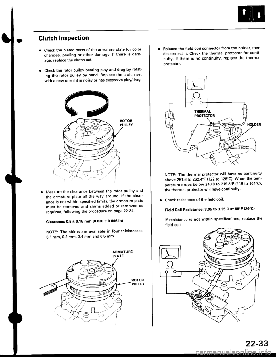
Check the plated parts of the armature plate for color
changes, peeling or other damage lf there is dam-
age. replace the clutch set.
Check the rotor pulley bearing play and drag by rotat-
ing the rotor pulley by hand Replace the clutch set
with a new one if it is noisy or has excessive play/drag
Measure the clearance between the rotor pulley and
the armature plate all the way around lf the clear-
ance is not within specified limits, the armature plate
must be removed and shims added or removed as
required, following the procedure on page 22-34
Cl€arance: 0.5 ! 0.15 mm {0.020 t 0.006 in)
NOTE: The shims are available in four thicknesses:
0.1 mm,0.2 mm,0.4 mm and 0.5 mm
. Release the field coil connector from the holder' then
disconnect it. Check the thermal protector for conti-
nuity. lf there is no continuity. replace the thermal
protecror,
NOTE: The thermal protector will have no continuity
above 251.6 to 262.4oF 1122lo 128'C). When the tem-
perature drops below 240 8 to 219.8"F (116 to 104"C),
the thermal protector will have continuity
. Check resistance of the field coil
Field Coil Resistance: 3.05 to 3.35 O at 68"F (20"C)
lf resistance is not within specifications, replace the
field coil.
22-33
Page 1458 of 2189
Compressor {SANDEN)
Clutch Overhaul
1. Remove the center nut while holding the armatureplate with the tool.
CENTER NUT17.6 N.m {1.8 kg{.m,'t3 tbnft}
2. Remove the armature plate by pulling it up by hand.
ARMATURE PLATE
A/C CLUTCH HOLDER{Commerciallv aveilable)Robinair: P/N 10204Kent-Moore: P/N J37872
22-34
3. Remove snap ring B with snap ring pliers.
NOTE:
. Be careful not to damage the rotor pulley and
compressor during removal/installation.. Once snap ring B is removed, replace it with anew one.
A
\/
G::.
Remove the rotor pulley from the shaft with a puller
and the special tool.
NOTE: Place the claws of the puller on the back of
the rotor pulley, not on the belt area; otherwise the
rotor pulley can be damaged.
. r \:g2rl -/ /
.-!L;j'/
TWO JAW PULLER{Commercially
Page 1461 of 2189
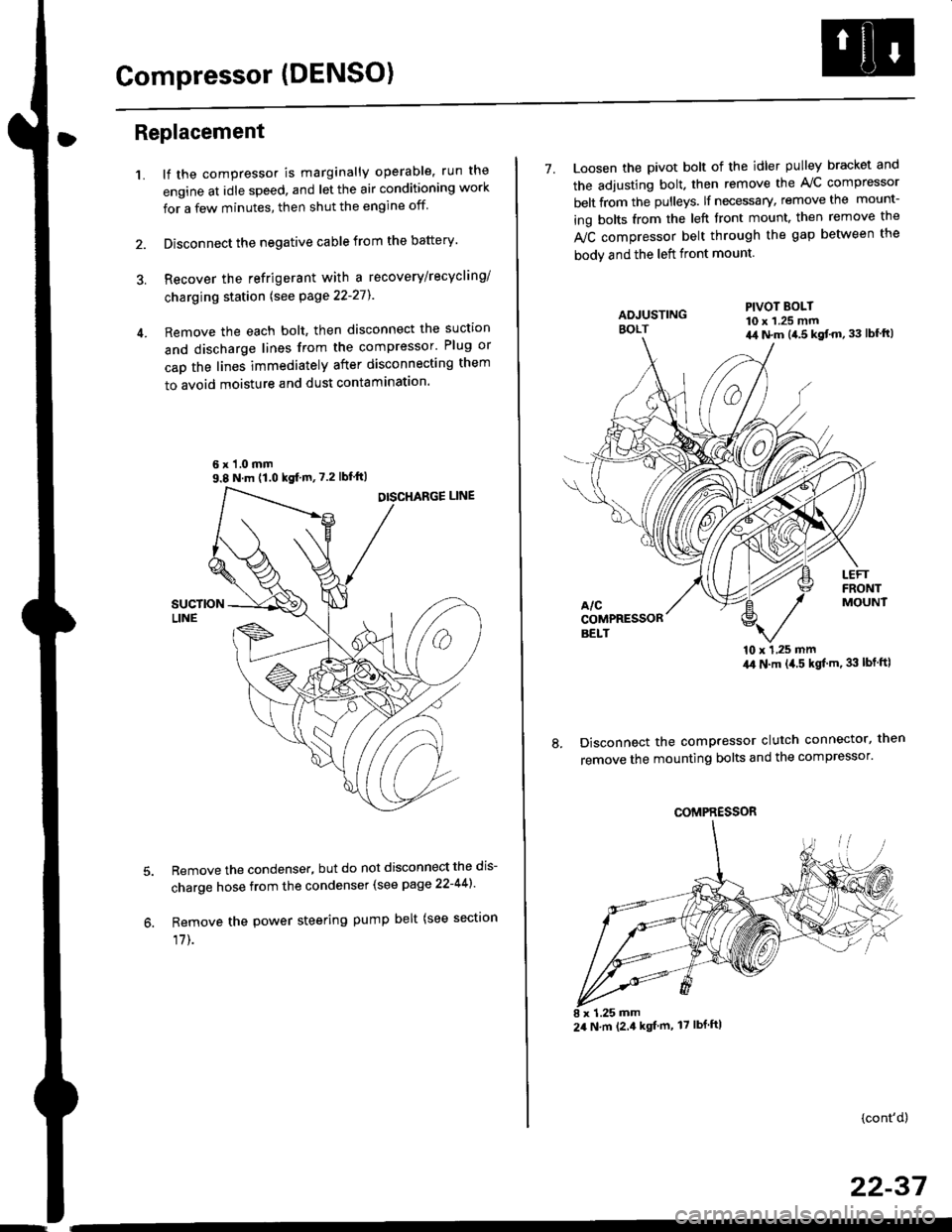
Compressor (DENSO)
Replacement
1.lf the compressor is marginally operable, run the
engine at idle speed, and let the air conditioning work
for a few minutes, then shut the engine off
Disconnect the negative cable from the battery'
Recover the refrigerant with a recovery/recycling/
charging station lsee page 22-271
Remove the each bolt, then disconnect the suction
and discharge lines from the compressor' Plug or
cap the lines immediately after disconnecting them
to avoid moisture and dust contaminatlon.
6 x '1.0 mm9.8 N.m (1.0 kgf m,7.2 lbfft)
Remove the condenser, but do not disconnect the dis-
charge hose from the condenser (see page 22-441'
Remove the power steering pump belt (see sectron
17]-.
7. Loosen the pivot bolt of the idler pulley bracket and
the adjusting bolt. then remove the A,/C compressor
belt from the pulleys. lf necessary, remove the mount-
ing bolts from the left front mount. then remove the
fuC compressor belt through the gap between the
bodv and the left front mount.
'10 x 1,25 mm4,0 N.m (,1.5 kgf'm. 33 lbt ftl
Disconnect the compressor clutch connector, then
remove the mounting bolts and the compressor'
PIVOT BOLT10 x 1.25 mm4,1 N.m (4.5 kgt'm,33 lbfft)
COMPRESSOR
24 N.m (2.4 kgf m, 17 lbf ftl
(cont'd)
22-37
Page 1464 of 2189
Compressor (DENSOI
Clutch Inspection
Check the plated parts of the pressure plate for colo.changes, peeling or other damage. lf there is dam-age, replace the clutch set.
Check the pulley bearing play and drag by rotatingthe pulley by hand, Replace the clutch set with a newone if it is noisy or has excessive play/drag.
Measure the clearance between the pullev and thepressure plate all the way around. lf the clearance isnot within specified limits, the pressure plate must beremoved and shim(s) added or removed as required,
following the procedure on page 22-41.
Clearanca:0.5 t 0.15 mm {0.020 r 0.006 in}
NOTE: The shims are availabte in three thicknesses:0.1 mm,0.3 mm and 0.5 mm.
22-40
. Check resistance of the field coil. lf resistance is notwithin specifications, replace the field coil.
Fiald Coil Resistanc€: 3.it to 3.8 O at 20.C l68.Fl