1998 HONDA CIVIC check engine light
[x] Cancel search: check engine lightPage 379 of 2189

PGM-FI System
(From page 11-109)
Replace the sensor that causedthe light to go out.Does the N4lL go OFF?
Check fo. a short in the wi.os(VCC lines):':. Turn the ignition switch OFF.2. Disco n n ect the ECM/PCMconnector D (16P).
3. Check for continuity betweenbody ground and ECM/PCMconnector terminals D4 andD10 individually.
Ropair short to body groundin the wire betweon ECM/PCM {O4) and MAP s6n3or.Repair short to body groundin the wire between ECM/PCM lD10l, the TP sensor, theEGR valve lift sensor {D16Y5engine) and/or the Fuel tankpressure sensor {'96 Dl6Ygengine lcoupe),'97 D16Y7engine (coupe: KL model,sedan: KL (LXl model), '97
D16Y8 engine (coupe: allmodels, sedan: KL model. €8-allmodelsl.
ls there continuity?
Check tor rn open in the wires(lGP lines):1. Disconnect the fuel injectorsand IAC valve connectors,2. Turn the ignition switch ON (ll).3. Meas u re voltage betweenbody ground and ECM/PCMconnector terminals A11 and424 indivjdually.- Repair open in the wirels)between ECM/PCM (A11,A24land PGM-Fl main relay.- Check for poor connectionsor loose wiras at the PGM-FImain relay,- Test the PGM-FI mdin relavlsee pag6 11-237).
ls there battery vohage?
Check for an open in the wires(LG line3):1. Reconnect all sensor connectors.2. Reconnect the ECM/PCM con-nector D (16P).
3. Turn the ignition switch ON (ll).4. Measure vo ltage betweenbody ground and ECM/PCMconnector terminals Ag andA22 individually.
Repair open in the wirolglb€twe€n ECM/PCM {A9, A22} andG101 that had more than 1.0 V.
ls there less than 1.0 V?
Substitute 6 known-good ECM/PCM and r€check. lf symptom/indication 9o€s away, replacethe original ECM/PCM.
Engine Control Module/Powertrain Control Module (ECM/pCMl
('96 - 98 Models, '99 - 00 D16Y5 engine with M/Tl (cont,dl
ECM/PCM CONNECTOR D {16P}
Wire side of female terminals
ECM/PCM CONNECTOR A (32P}
Wire side of female terminals
11-110
LG1
VCCl {YEL/RED}
IGP 1{YEL/BLKI
2I11
1213l5t6Itt8t9202321
25272a2930
IGP 2(YEL/BLKIv) (l
{8RN/BLK)
I258tol1'12tt11t5l617t8t920232a
2A2330
LG2{8RN/8LK}
Page 380 of 2189
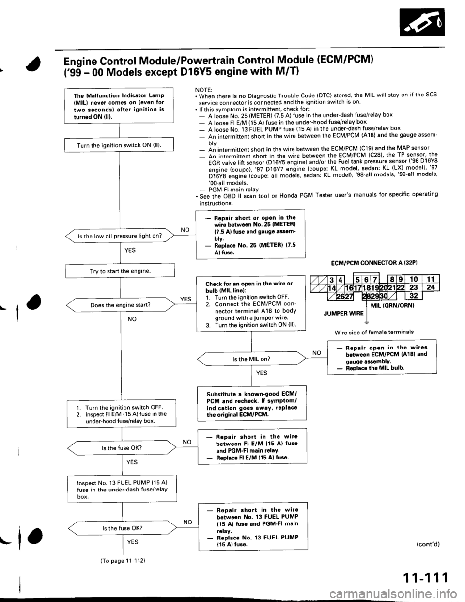
Engine Control Module/Powertrain Control Module (ECM/PCM)
('95 - 00 Models except Dl6Y5 engine with M/T)
NOTE:. When there is no Diagnostic Trouble Code lDTC) stored, the MIL will staY on if the SCS
seruice connector is connected and the ignition switch is on.. lf this symptom is intermittent, check for:- A loose No. 25 (METER) {7.5 A) fuse in the underdash fuse/relay box- A loose Fl E/M (15 Alluse in the undeFhood fuse/relay box- A loose No. 13 FUEL PUMPfuse (15 A) in the under-dash fuse/relay box- An intermittent shon in the wire between the ECM/PCM (A18) and the gauge assem'
- an intermittent short in the wire between the ECM/PCM (C19) and the MAP sensor- An intermittent short in the wire between the ECM/PCM {C28), the TP sensor, the
EGR valve lift sensor (D16Y5 engine) and/or the Fuel tank pressure sensor ('96 D16Y8
engine (coupe),'97 D16Y7 engine lcoupe: KL model, sodan: KL (LX) model)"g7
Dt6Y8 engine (coupe: all mod;ls, sedanl KL model),'98-all models,'99-al' models''00-all models.- PGM'FI main relay. See the oBD ll scan tool or Honda PGM Tester user's manuals for specific operating
instructrons,
ECM,/PCM CONNECTOR A I32PI
Wire side of {emale terminals
The Mrlfunction Indicator LamP{MlL) never comes on {even tor
two seconds) after ignition is
turned ON lll).
Turn the ignition switch ON lll).
- Repair shott or open in thowire bstwoon No. 25 IMETER)l?.5 A)tuse and gauga tsom_blv.- Reolace No. 25 (METERI (7.5
Alluse.
ls the low oil pressure light on?
Try to start the engine.
Check for an opon in the wire orbulb (MlL line):1. Turn the ignition switch OFF.2. Connect the ECM/PCM con'
nector terminal A18 to bodyground with a iumper wire.
3. Turn the ignition switch ON (ll)
Does the engine start?
- Repair open in tho wire3
betwoon ECM/PCM (A18) andgaugo .*tembly.- Rool.ce the MIL bulb.
Substitute a known-good ECM/
PCM and rochoc&. lf sYmptom/indication goes sw6y, repl.ce
tho original ECM/PCM.Turn the ignition switch OFF.Inspect Fl E/M (15 A)fuse in theunderhood Iuse/relay box.
Rop.ir short in the wirc
betwo€n Fl E/M (15 A) luso
and PGM-Fl mrin rGl.y.Reol.ce Fl E/M (15 A)tusa.
lnspect No. 13 FUEL PUMP {15 A}
luse in the under-dash fuse/relay
- Reoair short in the wiro
between No. 13 FUEL PUMP
115 Al luse sod PGM-FI mainrelay.- Reolace No. 13 FUEL PUMP115 A) tuse.
(To page 11 112)
(cont'd)
11-111
.f,
Page 448 of 2189
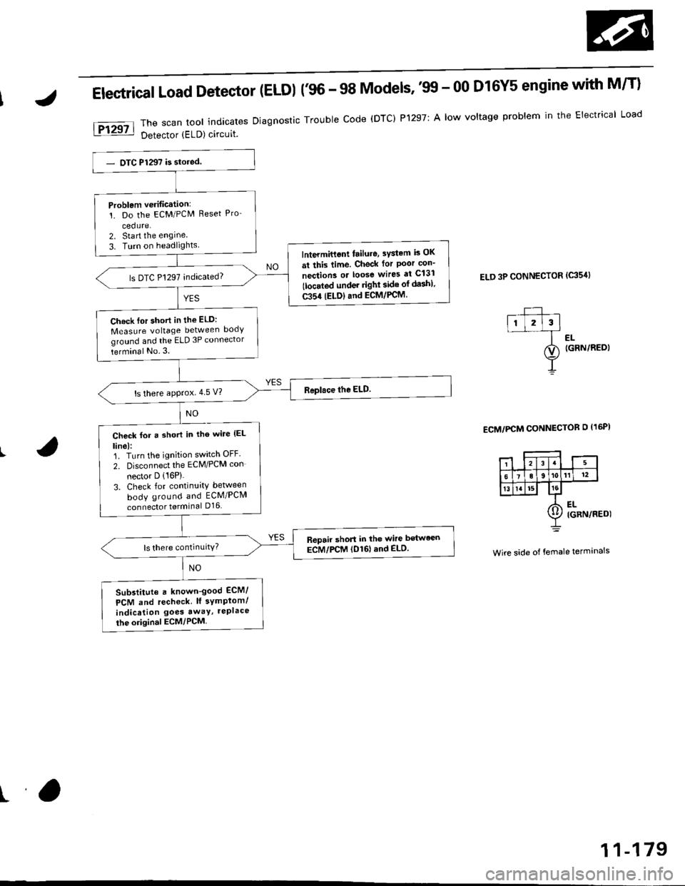
Electrical Load Detector (ELDI {'96 - 98 Models,'tn - 00 D16Y5 engine with M/T}
The scan tool indicates Diagnostic Trouble code (DTC) P1297: A low voltage problem in the Electrical Load
Detector (ELD) circuit.
ELD 3P CONNECTOR (c35'rl
l-- ,ll l2l3l--f ..
ao (GRN/REDI
Y
ECM/PCM CONNECTOR O I16PI
Wire side of female terminals
Problem verification:'!. Do the ECM/PCM Reset Pro-
cedure.2. Sta rt the engine
3. Turn on headlightslntermittent tailure, sYstem is OK
at this time. Check for Poor con-
nection3 or loose wires at C131
tlocated under righl side of da3h).
C354 (ELDIand ECM/PCM.
ls DTC P1297 indicated?
Ch.ck lor short in the ELD:
Measure voltage between body
ground and the ELD 3P connector
terminal No.3.
ls there approx.4 5 V?
Check for a short in tho wile (EL
linel:1. Turn the ignition switch OFF'
2. Disconnect the ECM/PCM con
nector D (16P)
3. Check for continuity between
body ground and ECM/PCM
connector terminal D16
R6pair short in the wire between
ECM/PCM (D161and ELD.
Substitute a known-good ECM/
PCM and recheck lf symplom/
indication goes awaY, rePlace
the original ECM/PCM
ra
11-179
Page 449 of 2189
PGM-Fl System
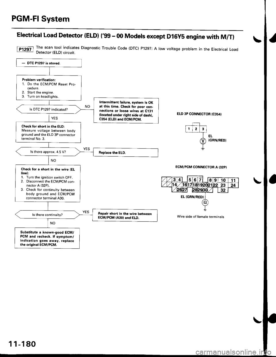
Elestrical Load Detector |ELD) t'glf - 00 Models except D16y5 engine with M/Tl
The scan tool indicates Diagnostic Trouble Code (DTC) P'1297; A low voltage probtem in the Electrical LoadDetector (ELD) circuit.
ELD 3P CONNECTOR tC354)
EL{GRN/REOI
ECM/PCM CONNECTOB A I32PI
Wire side of lemale terminals
Problem verilication:1. Do the ECM/PCM Reset Pro-cedure.2. Sta rt the engine.3. Turn on headlights.
Inlermittont failur6. systom i3 OKat this time, Chock tor ooor con-nestions or loose wires at C131(locrted undor ight side ot d.shl,C354 (ELDI and ECM/PCM.
Check for short in th6 ELD:Measure voltage between bodyground and the ELD 3P connectorterminal No.3.
ls there approx. 4.5 V?
Check to. a short in the wne (ELlinel:'L Turn the ignition switch OFF.2. Disconnect the ECM/PCM con-nector A (32P).
3. Check tor continuity betlveenbody ground and ECM/PCMconnector terminal A30.
Repair short in the wile betweenECM/PCM lA30) and ELD.ls there continuity?
Sub3titute a known-good ECM/PCM and rech€ck. It symptom/indication goes away. replacethe o.iginal ECM/PCM.
1 1-180
Page 450 of 2189
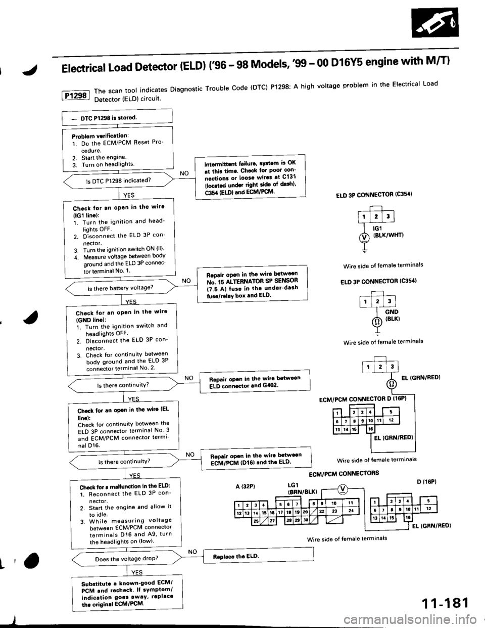
Elestrical Load Detector (ELD) f96 - 98 Models''99 - 00 D16Y5 engine with M/T)
ThescantoolindicatesDiagnosticTroubleCode(DTC)P1298:AhighvoltageproblemintheElectricalLoad
Detector (ELD) circuit
ELD 3P CONNECTOR {G's'I
Wire side ol female terminals
EL IGFN/REDI
Problom vcrificttion:
1. Do the EcM/PClVl Reset Pro-
cedure,2. Start the engine.
3. Turn on headlights.lntarmitt..rt l.ilur., ryttcm b OK
.t thia tim. Ch.ck lor Poo' con-
nections or looaa wir.3 at C131
lbcd.d und.r right ide ol dalhl'
Gl5a {EU)} .nd ECM/PCIYI
ls DTC P1298 indicated)
Ch.ck lor tn oPan in tho wir'
(lGl linol:1. Turn the ignition and head'
liohts OFF2. D]""onn""t the ELD 3P con_
nector-3. Turn the ignition switch ON {ll)'
4. Measure voltage between body
ground and the ELD 3P connec
tor terminal No. '1.
R.oair ogan in tha wira Mw"n
ru". rs ltTEnrlton SP SelSOn
t?.5 A, fu!. in th. undcr-dr3h
tu3e/r.l!Y box .nd ELD.
Chcck lor tn oP.h in thc wire
{GND lincl:1. Turn the ignition switch and
headlights OFF.
2. Disconnect the ELD 3P con_
nector'3. Check for continuity between
body ground and the ELD 3P
connecto. terminal No 2
Raprir opcn in the wira bstwt€n
ELD conncctor lnd G/O2.
Ch.ck lor !n oplo in tha wirc IEL
lin.l:Check for continuity between the
ELD 3P connector terminal No 3
and ECM/PCM connector termi
nal D'16.
Rapaii opcn in the wira b€tw"n
ECM/FCM (I)161 .nd th. ELD'
Ch.d( fo. r m.llunction in thc ELD:
1. Reconnect the ELD 3P con'
2. Start th€ engine and allow it
to idle.3. Wh ile measuring voltage
beNveen ECM/PCM connector
terminals D16 and A9, turn
the headlights on {low).
Does the voltage droP?
Sub3titut. . known_good ECM/
PCM .nd rcch.ct. lt sYmptom/
indication goas away/ iapllc'
thc origin.l ECM/PCM
wire side of lemale termrnals
Wire side of Iemale terminals
t'a
)
1 1-181
Page 451 of 2189
PGM-FI System
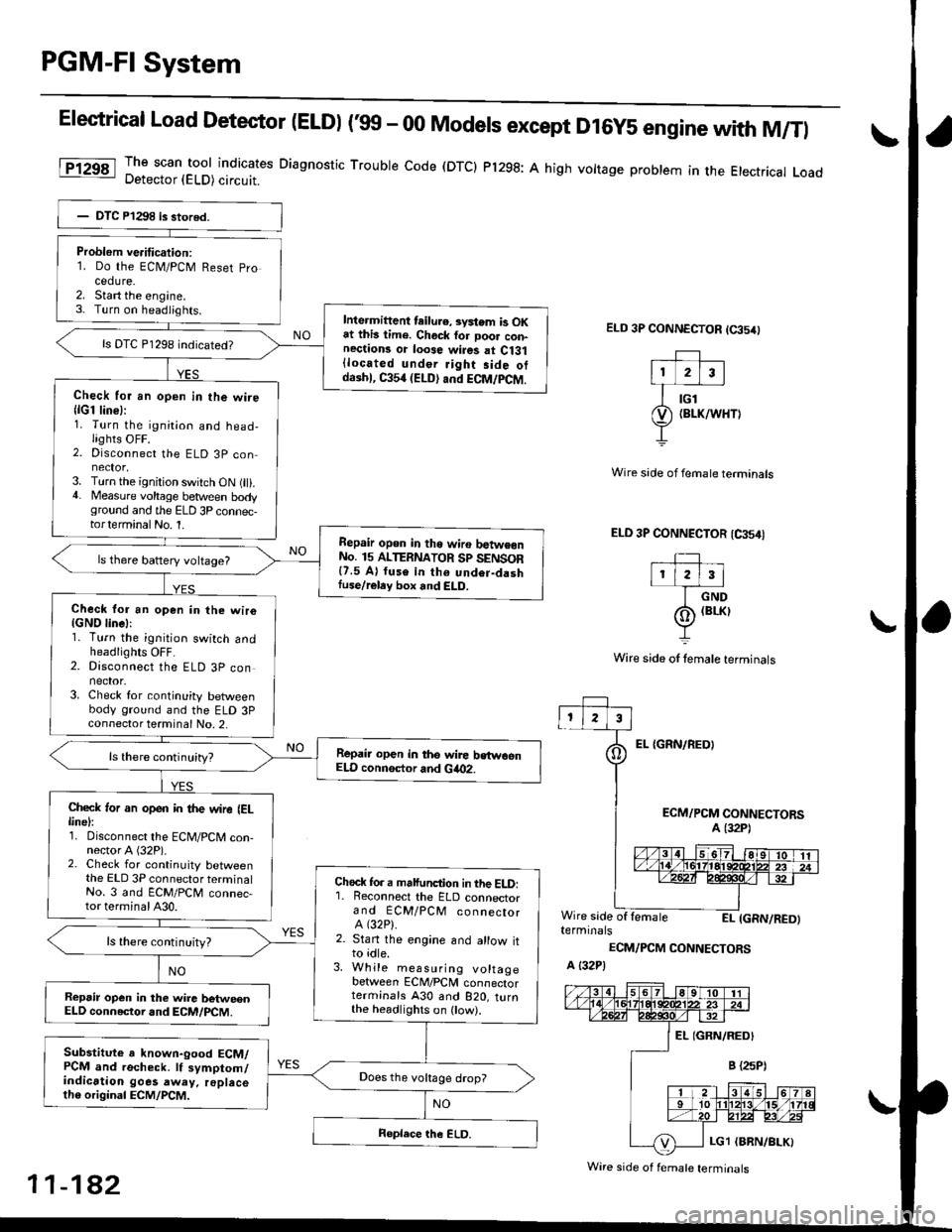
Elestrical Load Detector (ELDI ('99 - 00 Models except D16y5 engine with M/Tl
The scan tool indicates Diagnostic Trouble code (DTCI Pl298: A high vottage problem in the Etectrical LoadDetector (ELD) circuit.
ELD 3P CONNECTOR (65/0
EL {GRN/REOI
Wire side of fernale terminals
ELD 3P CONNECTOR (CA54I
TIr l2l3l
I crvo
(o) (BrKr
Y
Wire side of lemale terminals
ECM/PCM CONNECTORSA (32P1
Wire side of lemaleEI- IGRN/RED)terminals
ECM/PCM CONNECTORS
A {32P)
Problem ve.itication:1. Do the ECN4/PCM Reset pro
cedure.2. Start the engine.3- Turn on headiights.Inte.mittent teilu.e, svstem is OKat this lime. Chock for Door con-nections or loose wires at Ci31{located under Jight side otdaihl, C354 (ELD) and ECM/PCM.
ls DTC P1298 indicated?
Check for an open in the wire{lG1 line}:1. Turn the ignition and head-lights OFF.2. Disconnect the ELD 3P con
3. Turn the ignition switch ON (ll).4. Measure voltage between bodyground and the ELD 3P connec-torterminalNo. 1.
Repair opon in tho wiro batwe€nNo. 15 ALTERNATOR Sp SENSOR{7.5 A} fuse in th6 undor-dashIuse/reley box and ELD.
ls there battery voltage?
Check for an open in the wiro{GND linel:1. Turn the ignition switch andheadlights OFF.2. Disconnect the ELD 3P connector.3. Check for continuity betweenbody ground and the ELD 3Pconnector terminal No. 2,
Repair open in the wire bstwoenELD connsctor and Gia02.
Check ,or an open in the wire IELlinel:1. Disconnect the ECM/PCM con-nector A (32P).2. Check for continuity betweenthe ELD 3P connector terminalNo. 3 and ECM/PCM connec-tor terminal A30.
Chock fo. a malfunction in the ELD:'1. Reconnect the ELD connectorand ECM/PCM connectorA (32P).
2. Stan the engine and allow itto idle.3. While measuring voltagebetween ECM/PCM connectorterminals A30 and B2O, turnthe headlighrs on ow).
ls there continuity?
Repsir op€n in the wire betweenELD connector and ECM/PCM.
Substitute a known-good ECM/PCM and recheck. lf symptom/indication goes away. replacelh6 original ECM/PCM.
Does the vokage drop?
Wire side of f€male terminals
11-182
Page 461 of 2189
ldle Control System
ldle ControlSystem
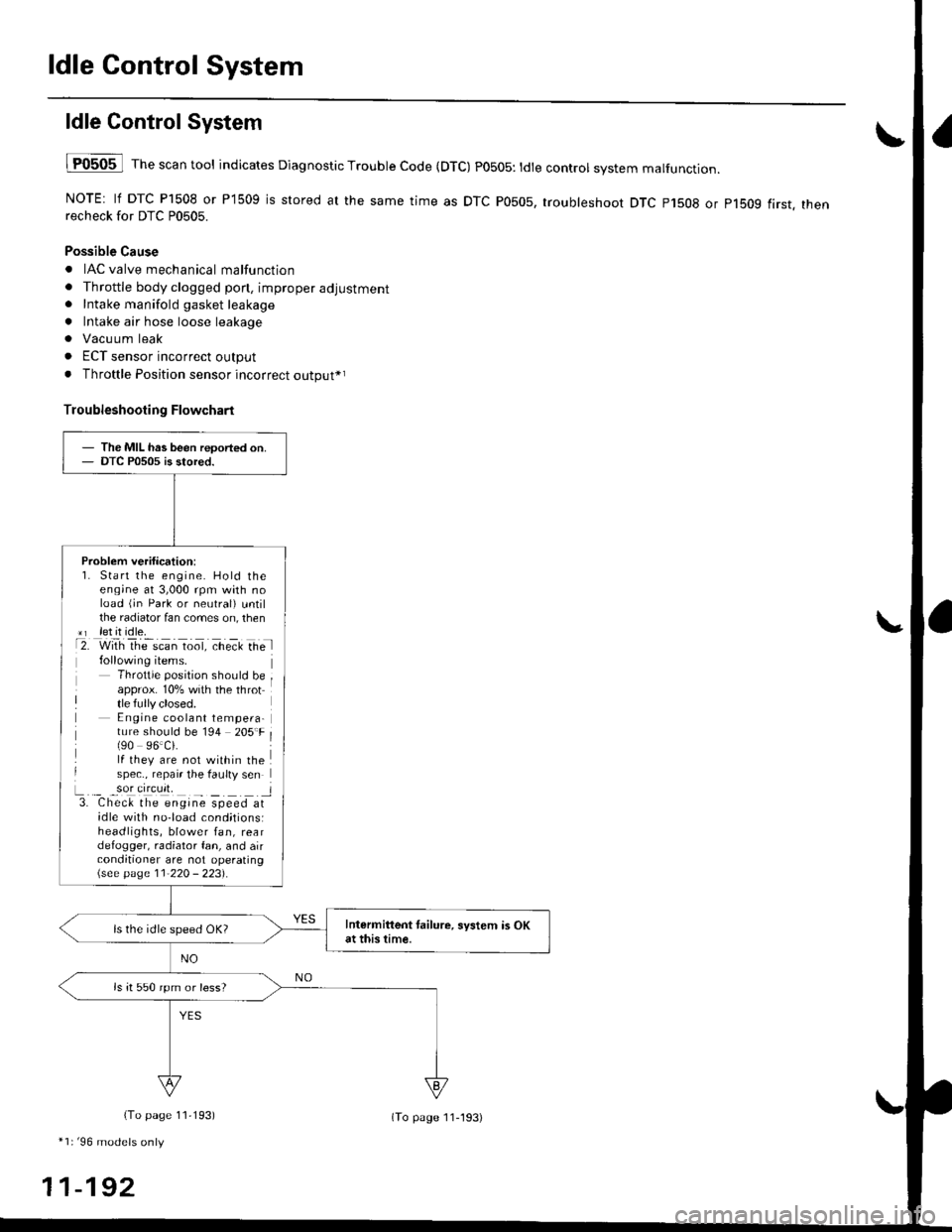
lF0505 l Th" """n tool indicates Diagnostic Trouble Code (DTC) PO5O5: tdte controt system malfunction.
NOTE: lf DTC P1508 or P1509 is stored at the same time as DTC P0505, troubleshoot DTC p1508 or p1bog first. thenrecheck for DTC P0505.
Possible Cause
. IAC valve mechanical malfunction
. Throttle body clogged pon, improper adjustment. Intake manifold gasket leakage
. Intake air hose loose leakage
. Vacu um leak
. ECT sensor incorrect output
. Throttle Position sensor incorrect output*r
Troubleshooting Flowchart
The MIL has been reoorted on.DTC P0505 is stored.
Problem verification:1. Start the engine. Hold theeng;ne at 3,000 rpm with noload (jn Park or neutral) untilthe radiator fan comes on, then*r let it idle.t2. with rhe scan toot, ct'eit Ge l
Throttle position should beapprox. 10% with the throttle fully closed.E ngine coolant tempera-ture should be 194 205'F(90 96.Ci.lf they are not within thespec., repair the faulty sen
L._ _9oI9[cr]41 l3. Chec& the engine speed atidle with no-load cond;tionsiheadlights, blower fan, reardefogger, radiator fan, and airconditioner are not operating\see page l1-22O - 223).
Intermittent tailure, system is OKat this time.ls the idle speed OK?
ls it 550 rpm or less?
(To page 11,193)
*1r'96 models only
11-192
(To page ll-193)
Page 477 of 2189

ldle Control System
Alternator (ALTI FR Signal {'96 - 98 Models,'99 - 00 Dl6y5 engine with M/Tl
ECM/PCM CONNECTORS
a {32P)
LGl(BRN/BLK)
Wire side of female terminals
ALT CONNECTORS IC1O4I
JUMPER
JUMPER WIRE
WIRE
Wire side of female terminals
ALT F{WHT/REO)
This signals the ECM/PCM when the Alternator (ALT) is charging.
Inspoction of ALT FR Signal.
Check tor a short in tfte wire (ALTF linel:1. oisconnect the 4P (3P)* con-nector from the ALT.2. Turn the ignition switch ON (ll).3. M easu re voltage betweenECM/PCM connector terminals C17 and A9.Check lor a sho.t in the wire {ALTF line):r. I urn rne tgn|lton swtlch ul-f,2. Disconnect the negative bat-tery cable from the baftery.3. Disconnect the ECM/PCM connector C {31P).4. Check for continuity betweenbody ground and ECM/PCMconnector terminal C17.
ls there approx. 5 V?
Check th€ operation of the ALT:1. Turn the ignition switch OFF.2. Reconnect the ALT 4P (3P)*connector to the ALT.3. Start the engine. Hold theengine at 3,000 rpm with noload (in Park or neutral) untjlthe radiator fan comes on, thenlet it idle.4. [,4easu re voltage betweenECM/PCM connector terminalsC17 and A9.
Repair short in the wire betwe€nthe ECM/PCM {Cl71and th€ ALT.
Substitute a known-good ECM/PCM and recheck. It prescribedvoltage is now available, roplacethe originrl ECM/PCM.
Does the voltage decrease whenheadlights and rear defogger areturned on?ALT FR signal is OK.
Check tor an open in the wire (AlTF linel:1. Turn the ignition switch OFF.2. Disconnect the negative bat-tery cable from the battery.3. Disco n nect the ECM/PCMconnector C (31P).4. Disconnect the 4P (3P)* con,nector from the ALT.5. Connect the ALT 4P 13P)l connector terminal No. 4 (No. 1)'to body ground with a iumper
6. Check lor continuity betweenbody ground and ECM/PCMconnector terminal C17,
Repair op6n wire botween th€ECM/PCM (C171rnd th€ ALT.ls there continuity?
c {31P)
1178I10
1112131415161718
232125a30
oALT F IWHT/REDI
4P3P*
1 2l
Flr
rr-ri-frwHr/ (V)
neor Y
*: Canada model
11-208
3I78910
1l1213l415161718/l
232125E30
oALT F IWHT/REDI