1998 HONDA CIVIC Radiator cap
[x] Cancel search: Radiator capPage 261 of 2189

Radiator
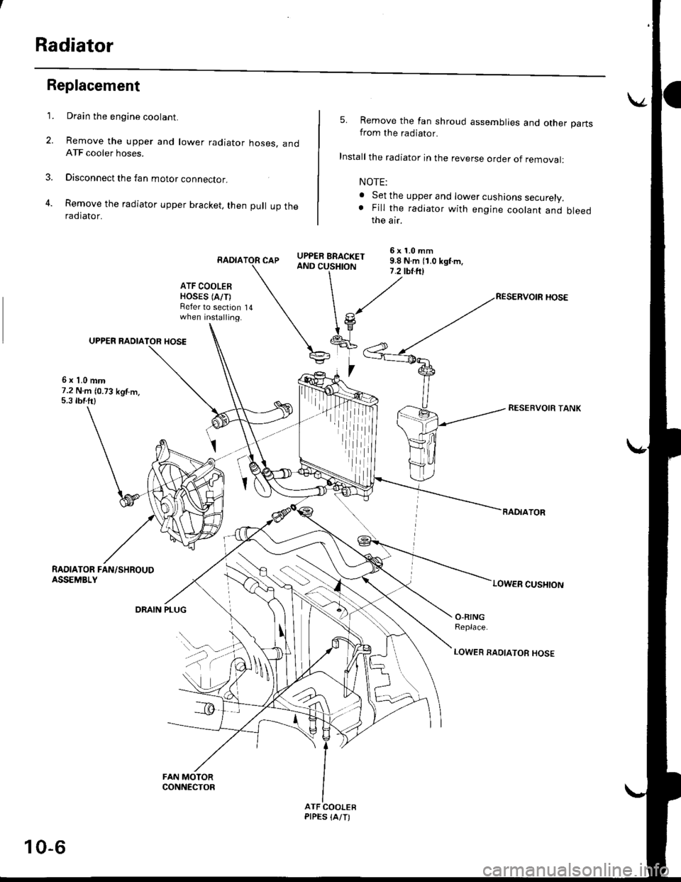
Replacement
Drain the engine coolant.
Remove the upper and lower radiator hoses, andATF cooler hoses.
Disconnect the fan motor connector.
Remove the radiator upper bracket, then pull up theraotator,
RADIA
ATF COOLERHOSES (A/T)Refer to sectionwhen installing.
UPPER RAOIATOR HOSE
6x1.0mm7.2 N.m (0.73 kgf.m.5.3 tbf.ft)
1.
2.
3.
5. Remove the fan shroud assemblies and other partsfrom the radiator.
Install the radiator in the reverse order of removal:
NOTE:
. Set the upper and lower cushions securely.. Fill the radiator with engine coolant and bleedthe air.
6x1.0mmCAPY|lT,PS:|" i.i ru- ii b rgr.-,AND CUSHION7.2 tbr.ftl
14
(
I
RESEBVOIR TANK
RADIATOR
LOWER CUSHION
RAOIATOR FAN/SHROUDASSEMBLY
DRAIN PLUGO-RINGReplace.
LOWER RAOIATOR HOSE
ATF COOLERPIPES {A/T)
,iiiiii
10-6
Page 262 of 2189

tl
Engine Coolant Refilling and Bleeding
CAUTION: when pouring engine coolant, be sure to
shut the relay box lid and not to lst coolant spill on the
eleqtrical parts or the paint. lf any coolant spills, rinse it
off immediately.
1. Slide the heater temperature control lever to maxl-
mum heat. Make sure the engine and radiator are
cool to the touch.
Remove the radiator caP.
Loosen the drain plug, and drain the coolant'
Remove the drain bolt from the cylinder block'
D16Y5. D16Y7, Dl6Yg sngines:
DRAIN PLUG
0d
I ro
78 N.m {8.0 kgl m.58lbt'ft)
6.
1.
B1642 engin€:
WASHERReplace.
DRAIN BOLT78 N m (8 0 kgf m' 58lbfft)
Apply liquid gasket to the drain bolt threads, then
reinstall the bolt with a new washer and tighten 't
securely.
Tighten the radiator drain plug securely
Remove, drain and reinstall the reservoir' Fill the
tank halfway to the MAX mark with water, then up
to the MAX mark with antitreeze.
(cont'd)
10-7
MAX MARK
Page 263 of 2189

Radiator
Engine Coolant Refilting and Bleeding (cont,dl
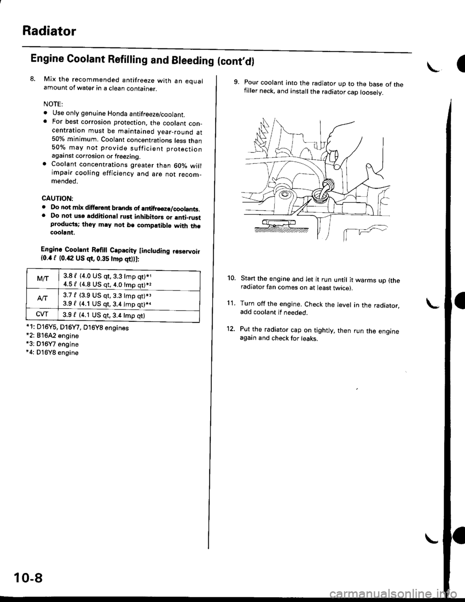
8. Mix the recommended antifreeze with an eoualamount of water in a clean container.
NOTE:
o Use only genuine Honda antifreeze/coolant.. For best corrosion protection. the coolant con_centration must be maintained year_round at50% minimum. Coolant concentrations less than50% may not provide sufficient protectionagainst corrosion or freezing.. Coolant concentrations greater than 60010 willimpair cooling efficiency and are not recom_mended.
CAUTION:
. Do not mix difforont brands ofar ilreeze/coolants.. Do not use additional rust inhibiiors or anti_rustproduqt3; they may not be compatible with thecoolant.
Engine Coolent Refi
Capacity Iincluding reservoir{0.4 f 10.42 US qr, 0.35 lmp qt),I;
*1: D16Y5, D16Y/, O16Y8 engines*2: 81642 engine*3; Dl6Y7 engine*4: Dl6Y8 engine
M/r3.8 f {4.0 US qt, 3.3 lmp qt)*1
4.5 / (4.8 US qt. 4.0 tmp qt)*,
Att3.7, (3.9 US qr,3.3 tmp qt).3
3.9 / (4.1 US qt,3.4lmp qt)*.
CW3.9 / (4.1 US qt,3.4 tmp qtl
10-8
\.-I
9. Pour coolant into the radiator up to the base of thefiller neck. and install the radiator cap looselv.
Start the engine and let it run until it warms up (theradiator fan comes on at least twicer.
Turn off the engine. Check the level in the radiator.add coolant if needed.
Put the radiator cap on tightly, then run the engineagain and check for leaks.
10.
11.
Page 264 of 2189

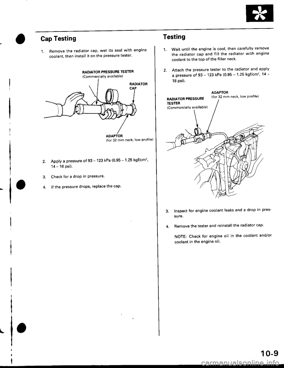
Cap Testing
1. Remove the radiator cap, wet its seal with engine
coolant, then install it on the pressure tester'
RADIATOR PR€SSURE TESTER(CommerciallY available)
RAOIATOR
(for 32 mm neck' low Pro{ile)
Apply a pressure of 93 - 123 kPa (0.95 - 'l 25 kgflcm'�'
14 - 18 psi).
Check for a drop in Pressure.
lf the pressure drops, replace the cap
I
t
ADAPTOR
Testing
LWait until the engine is cool, then carefully remove
the radiator cap and fill the radiator with engine
coolant to the top of the tiller neck
Attach the pressure tester to the radiator and apply
a pressure of 93 - '123 kPa (0.95 - 1.25 kgflcm'�, 14 -
18 psil.
RADIATOR PRESSURE
TESTER
lCommerciallY available)
ADAPTOR(for 32 mm neck, low Profile)
Inspect for engine coolant leaks and a drop In pres-
sure.
Remove the tester and reinstall the radiator cap
NOTE: Check for engine oil in the coolant and/or
coolant in the engine oil.
10-9
Page 361 of 2189

Troubleshooting
Engine/P_o,wertrain Control Module Terminal Arrangement('99 - 00 Models except Dl6Y5 engine with M/Tl
ECM/PCM CONNECTOR A (32P)Wire side ot temale terminalsNOTE:Standard battery voltage is l2 V
ECM/PCM CONNECTOR A I32PI
Sign!l
3BLU2WSS (EVAP 8YPAsS SOLENOIDDrives EVAP bypass solenoid vatve,With gn'tion swnch ON (lll banery votlage
LT GRN/I/VIITVSV {EVAP CONTNOL CANISTERVENTSHUTVALVE]Drives EVAP controt ca n isrer v€nt shutWilh ignilion switch ON {tl): b€ttery vottage
8LU/GNNC8S (CRUISE CONTSOL SIGOown shift signal inpot lrom c.uise conrrolWhen crurss control is used:purses
68ED/YELPCS {EVAP PURGE CONTROLSOTENOIOVALVE)Drives EVAP purge conrrol sotenoid vatve.With engine running, engine cootant, betow r54.F (6a,C):
With engine.unning, €ngine coolant, abov€ 154.F(68'C): duty conlrolled
YELATPD {AT GEAR POSITIONSWITCH)ootects A/T gear posnion swilch s,gnar.In otherthan @ posilion: Apprcx. 5 V
8BLK,IflHTSO2SHTC (SECONDARY HEATED OXYGEN SENSOS HEATEFCONTFOL)
Drives sscondary h€ared oxygen senso.Wilh isn,rion swirch ON (ll):banery votraseWith lully warm6d dp€ngire runn'ng:dury controled
LT GRNATPNP (AT GEAF POSITIONSWITCH)oereds A/T 9€a r position switch signat.In Parr or neulrsl:0 VIn anyother position approx.5 v
t088NSCS (SERVICE CHECK SIGNAL)Oetects ssruice check connecror signal(the signalcausing a OTC indication)with rh€ t6rminal connected: 0 vWith the rerm ina I disconneded: abour 5 V of ban€ry
GNN/BIKD4IND (D4INDICATON]Drives Oa indicaio. lighr.With D4 indicator lightturned ON: O VWith D4 indicator lightturned OFF: battery vo ttageG8N/YETFTF (FUEL PUI\,4P SELAY)Orivos tuel pump relay,0V for two s€conds lfrer turnrng rgnilior swtcn ON(ll), then batt€ry voltage11BTI(REDACC (Al/C CTUTCH SELAY)Drives A./C clutch reray.With compressor ON:O VWilh comp.ssor OFF; battery vottage18GFN/OFNMI! (A,IAIFUNCTION INDICA.TOF LIGHT)With MlLturned ON:0 VWith l\,llL tornod OFF|batrery votrsge198tuNEP (ENGINE SPEED PUTSEIOulputs6ngine speed pulse,Wilh engin6.unning: putses
20GFNFANC {SADIATOR FAN CONTnoL)Orives radiarortan relay.Wirh r.distor t6n running:OVWith radiatortan stopped: banery vottage21ELUA/ELK LINESends and r€ceives s.an lool signal.With ignition switch ON (ll):p!ts€s
22'lBLUATP L {AT GEAS POSITIONswtTcH)Oelocis A"/T gear posirion switch siSnat.In othfflhan E position: Apprcx. 5 V
23SHO25 (SECONOARY HEATEDOXYCEN SENSOR, SENSOF 2)Detects secondsry hoar€d oxygen sensorWith lhronle f! lly or'6ned from idte with fu ywarmod up engine: above 0.6 vWiih th.onl6 quickb, closd:below 0,4 V24STS ISTAFTEN SWITCH SIGDebcrs staner switch signat.Wirh srarterswitch ON (tttJ: batteryvottogeWith sraftsr cwirch OFF:0 V26GFNPSPSW iPlS PNESSURESWITCII SIGNAL)Derecrs PSP switch signat.Atidle with steoring wheolin srraightahead position: O VAt idl6with steering wheetal fult lock: barery vo ttags27BLU/REOACS (AJC SWITCH SIGNALJOer*ts ,ay'C swirch signat.Wiih ty'C switch ON;0VWilh Ay'C switch OFF|aboor 5VWHT/REDSLU iINTERLOCK CONTROIUNIT)Drivos interloct control unit.With ignltion switch ON (ll)and brake pedaldepresed: batlory volrage29LT GRNPTANK (FUEL TANK PFESSUEESENSOR)Oer6ds lu€l tank pr€ssura sonsor signat.Wilh ig.rrrd swirch ON rttr and fuetti
cap ooen6d.
30GRN/FEOEr (ELOIWith parking lighlsrurned on ar idteiaboui 2.5- 3.S VWirh low beam he€dlig hts turnqd on ai idts: aboul 1.52.5 V32GRN/'WHTAKSW (BFAKE SWITCH)Detets brak€ swrtch signEt,With brake pedal r6l€ased:0 VWhh brake pedaldepres*d: battery voltEse'1:A./T (D16Y7, D16Y8 engine)*2: rvt/T13: CVT (D16Y5 engine)
11-92
Page 489 of 2189

ldle Control System
ldle Speed Setting
Inspection/Adiustmenl
'96, '97 Dl6Y5. '96 - 00 Dl5Y8 sngine with M/T
NOTE:
. Before setting the idle speed, check the following
items:- The MIL has not been reported on.- lgnition timing- Spark plugs- Air cleaner- PCV system
o (Canada) Pull the parking brake lever up. Start the
engine, then check that the headlights are off.
1. Start the engine. Hold the engine at 3.000 rpm withno load (taansmission in neutral) until the radiatorfan comes on, then let it idle.
2. Connect a tachometer.
3. Disconnect the IAC valve connector.
4.lf the engine stalls, restart the engine with the accel-
erator pedal slightly depressed. Stabilize the rpm at1,000, then slowly release the pedal until the engineidles.
Check idling in no-load conditionsr headlights. blowerfan. rear defogger, radiator fan, and air conditioner
are not operating.
ldle spsed should be:
450 1 50 rpm
11-220
Adjust the idle speed, if necessary, by removing thecap and turning the idle adjusting screw.
NOTE; After adjusting the idle speed in this step,recheck the ignition timing (see section 23).
lf it is out of spec, go back to step 4.
IDLE
6. Turn the ignition switch OFF.
7. Reconnect the 2P connector on the IAC valve, then
do the ECM reset procedure.
8. Restart and idle the engine with no-load conditionsfor one minute, then check the idle speed.
NOTE: (Canada) Pull the parking brake lever up.Start the engine, then check that the headlights areoff.
ldle sp€sd should b€:
670 i 50 rpm IUSA)750 t 50 rpm {Canada}
9. ldle the engine tor one minute with headlights {Low)ON. and check the idle speed.
ldle speed should be:
750 :r 50 rpm
10. Turn the headlights off. ldle the engine for oneminute with heater fan switch at Hl and air conditioneron, then check the idle speed.
ldle speed should be:
810150 rpm
NOTE: lf the idle speed is not within specification,see Symptom Chan on page 11-84.
Page 490 of 2189

t
t
I
'96.'97 D16Y5 engine with CVT,'96 - 00 D16Y8 ongins
with A/T and'96 - 00 Dl6Y7 €ngine
Adiust the idle speed using a Honda PGM Tester if pos-
sible. lf not, use the following procedure:
NOTEI
. Leave the IAC valve connected
. Betore setting the idle speed. check the following
items:- The MIL has not been reported on'
- lgnition timing
- Spark Plugs- Air cleaner- PCV system
1. Connect a tachometer.
2. Start the engine. Hold the engine at 3,000 rpm wirh
no load (in Park or neutral) until the radiator fan
comes on, then let it idle.
3. Check the idle speed with no-load conditions: head-
iights, blower fan, rear defogger, radiator fan, and
air conditioner are not operatlng
ldl€ spoed should be:
USA:
D16Y5 engine with CVT, D16Y7 engine with A/T'
Dl6YB engine with A/T:
700 :r 50 rpm (in E or El Positionl
D16Y7 engine with M/T:
670 i 50 rpm
Canada:
Dl6Y8 sngin€, Dl6Y7 engins:
M/T750 t 50 rpm
NT750 1 50 rpm (in E or El Position)
Adjust the idle speed, if necessary, by removing the
cap and turning the idle adiusting screw 1/2-turn
clockwise or counterclockwise
D16Y5, D16Y8 engine:
IDLEADJUSTING
Dl6f, ongine:
NOTE: When you remove the ACL housing, do not
disconnect the IAT sensor connector
After turning the idle adjusting scrow 1/2-turn'
check the idle speed again. lf it is out of spec, turn
the idle adjusting screw 1/2-turn agaan'
NOTE: Do not turn the idle adjusting screw more
than 1/2-turn without checking the idle speed'
ldle the engine for one minute with heater fan
switch at Hl and air conditioner on, then check the
idle speed.
ldle speed should be:
M/T810150 rpm
A/T. CvT810 t 50 rpm (in El or E Position)
NOTE:
. Do not turn the idle adjusting screw when the air
conditioner is on.
. lf the idle speed is not within specification. see
Symptom Chart on page 11-84 (cont'd)
11-221
Page 491 of 2189

ldle Control System
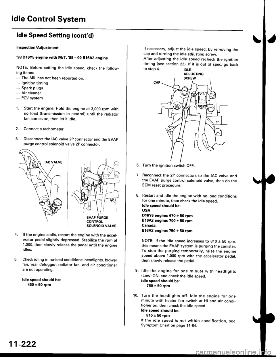
ldle Speed Setting (cont'dl
Inspeqtion/Adiustment
38 D16Y5 engine whh M/T,'99 - 00 81642 engine
NOTE: Before setting the idle speed, check the follow-ing items;- The MIL has not been reported on.- lgnition timing- Spark plugs- Air cleaner- PCV system
'1. Start the engine. Hold the engine at 3,000 rpm withno load (transmission in neutral) until the radiatorfan comes on, then let it idle.
Connect a tachometer.
Disconnect the IAC valve 2P connector and the EVAPpurge controlsolenoid valve 2P connector.
EVAP PURGECONTROLSOLENOID VALVE
lf the engine stalls, restart the engine with the accel-erator pedal slightly depressed. Stabilize the rpm at1.000, then slowly release the pedal until the engineidles.
Check idling in no-load conditions: headlights, blowerfan, rear defogger, radiator fan, and air conditionerare not operating.
ldl€ speed should be:
450 i 50 rpm
11-222
lf necessary, adjust the idle speed, by removrng lnecap and turning the idle adjusting screw.After adjusting the idle speed recheck the ignitlontiming (see section 23). lf it is out of spec, go backto step 4. |DLE
6. Turn the ignition switch OFF.
7. Reconnect the 2P connectors to the IAC valve andthe EVAP purge control solenoid valve, then do theECM reset procedure.
8. Restart and idle the engine with no-load conditionsfor one minute, then check the idle sDeed.ldle speed should bo:
USA:
D16Y5 engine: 670 i 50 rpm
81642 engine: 700 i 50 rpm
Canada:
81642 engine: 750 t 50 rpm
NOTE: lf the idle speed increases to 8lO t 50 rpm,this means the EVAP system is purging the canister.To stop the purging temporarily, raise the enginespeed above 1,000 rpm with the accelerator pedal,
then slowly release the pedal.
9. ldle the engine for one minute with headlights(Low) ON. and check the idle speed.
ldle speed should be:
750 i 50 rpm
10. Turn the headlights off. ldle the engine for oneminute with heater fan switch at Hl and air condi-tioner on, then check the idle soeed.ldls speed should be:
810 t 50 rpm
lf the idle speed is not within specification, seeSymptom Chart on page 11-84.