1998 HONDA CIVIC Piston rod
[x] Cancel search: Piston rodPage 215 of 2189
Connecting RodsPiston Pins
Selection
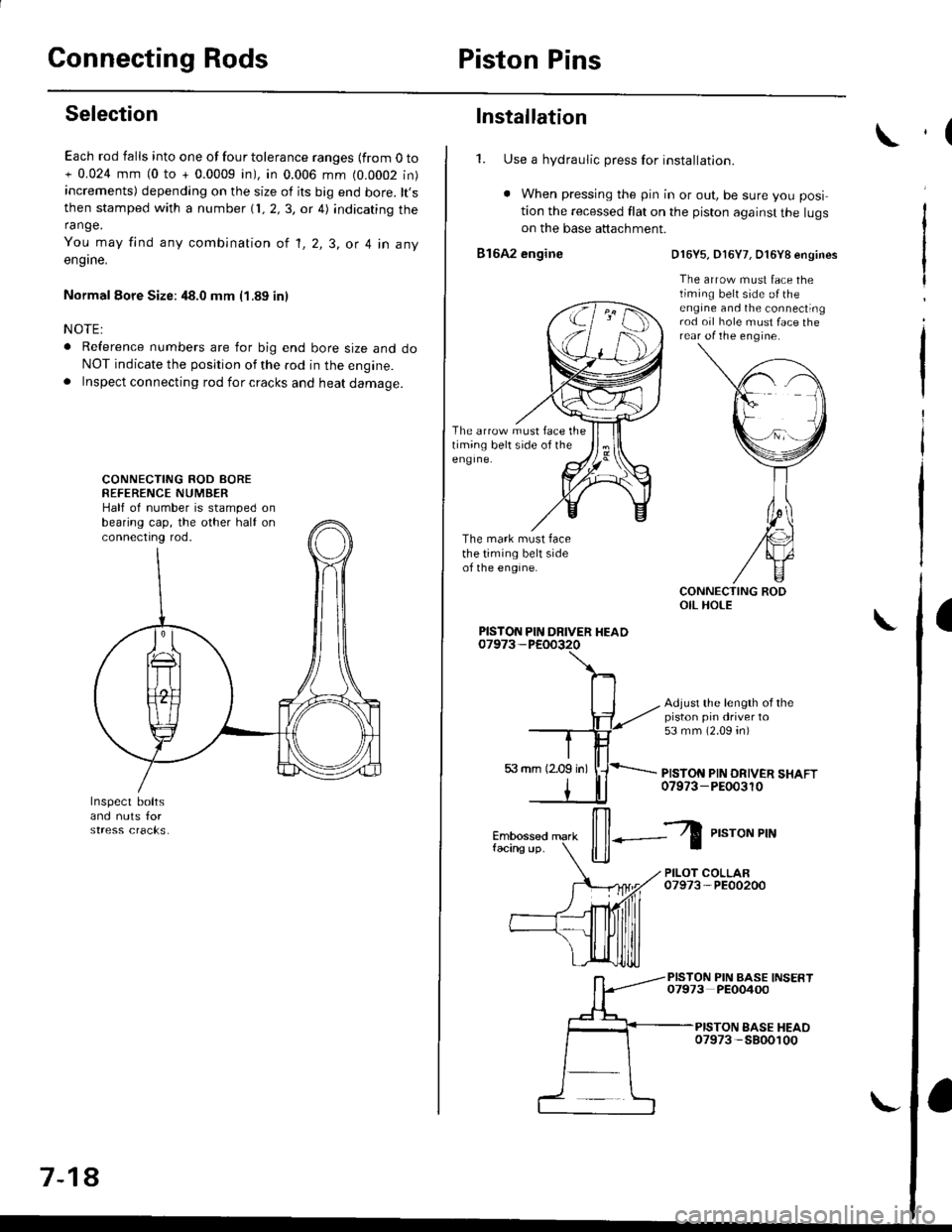
Each rod falls into one of four tolerance ranges {from O to+ 0.024 mm (0 to + 0.0009 in), in 0.006 mm (0.0002 in)increments) depending on the size of its big end bore. lt,sthen stamped with a number {1, 2,3, or 4) indicating therange.
You may find any combination ot l, 2, 3, or 4 in any
engrne.
Normal Eore Size: 48.0 mm (1.89 in)
NOTE:
o Reference numbers are for big end bore size and doNOT indicate the position of the rod in the engine.. Inspect connecting rod for cracks and heat damage.
CONNECTING ROD AOREREFERENCE NUMBERHalf of number is stamped onbearing cap, the other half onconnectrng rod.
7-18
Installation
1. Use a hydraulic press for installation.
. When pressing the pin in or out, be sure you posi
tion the recessed flat on the piston against the lugson the base attachment.
816A2 engine
The arrow must face thetiming belt side of theeng Ine.
The mark must facethe timing belt sideof the engine.
D16Y5, D16Y7, O16Y8 engines
The arrow must face thetiming belt side o{ theengine and the connectingrod oil hole must face therear of the engine.
Adjust the length of thepiston pin driver to53 mm (2.09 4n)
PISTON PIN DRIVER SHAFT07973-PEOo3r0
PISTON PIN DRIVER HEAD
il--Z
P,"roNPrN
PILOT COLLAR07973-PE00200
PISTON PIN BASE INSERT07973 PEO0400
PISTON EASE HEAO07973 -5800100
,(
a
Page 216 of 2189
lnspection
1.
Oversize:
Oversize:
NOTE; All replacement piston pins are overslze.
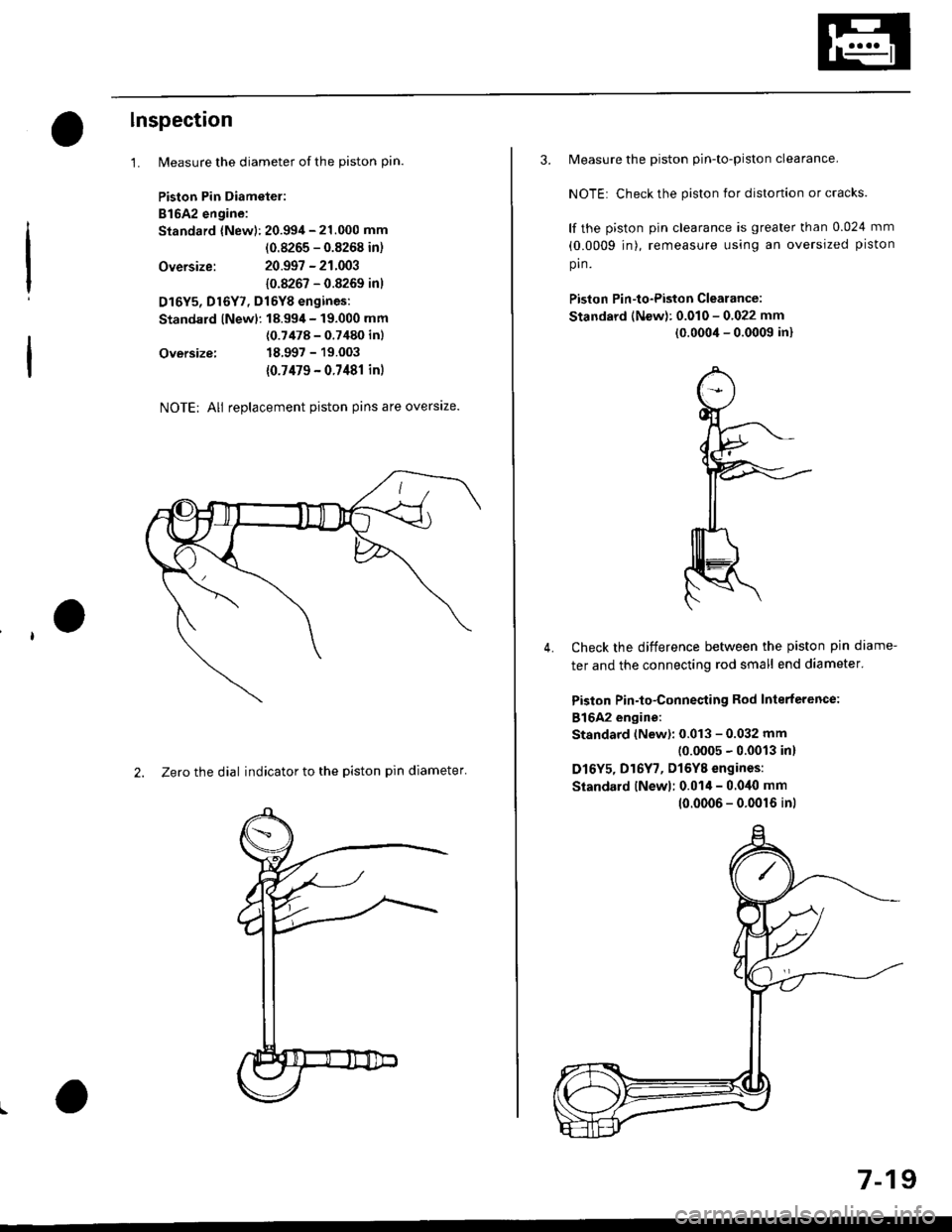
2. Zero the dial indicator to the piston pin diameter'
Measure the diameter of the piston pin.
Piston Pin Diametel:
B16A2 engine:
Standard {New): 20.994 - 21.000 mm
(0.8265 - 0.8268 in)
20.997 - 21.003
10.8267 - 0.8269 inl
D16Y5, Dl6Y7, Dl6YB engines:
Standard lNewl: 18.99,1- 19.000 mm
(0.7478 - 0.7480 inl
18.997 - 19.003
{0.7479 - 0.7481 in)
3. Measure the piston pin-to-piston clearance.
NOTE: Check the piston for distortion or cracks.
lf the piston pin clearance is greater than 0.024 mm
(0.0009 jn), remeasure using an oversized piston
pin.
Piston Pin-to-Piston Clearance:
Standard (New): 0.010 - 0.022 mm
(0.0004 - 0.0009 in)
Check the difference between the piston pin diame-
ter and the connecting rod small end diameter'
Piston Pin-to-Connesting Rod Interterence:
816A2 engine:
Standard (New): 0.013 - 0.032 mm(0.0005 - 0.0013 in)
D16Y5, D16Y7, Dl6YB engines:
Siandard lNewl; 0.014 - 0.040 mm
4.
10.0006 - 0.0016 inl
7-19
Page 217 of 2189
Piston Rings
End Gap
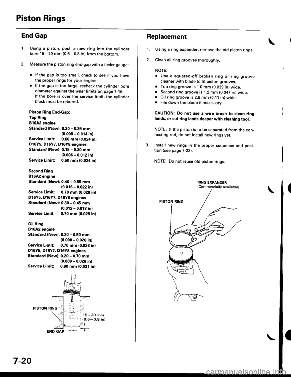
1.Using a piston, push a new ring into the cylinderbore 15 - 20 mm (0.6 - 0.8 in) from the bottom.
Measure the piston ring end-gap with a feeler gauge:
. lf the gap is too small, check to see if you have
the proper rings for your engine.. lf the gap is too large. recheck the cylinder borediameter against the wear limits on page 7-16,
lf the bore is over the service limit, the cvlinderblock must be rebored.
Pkton Ring End-cap:
Top Ring
81642 engino
Siandtrd (New): 0.20 - 0.35 mm
{0.008 - 0.01,1 in)
Service Limit: 0.60 mm l0-02i1 inl
D16Y5. Dl6Y7, D16Y8 enginos
Standard lNewl: 0.15 - 0.30 mm
{0.006 - 0.012 in)
Ssrvic€ Limit 0.60 mm {0.024 inl
Socond Ring
816A2 ongina
Standard (Nowl: 0.40 - 0.55 mm
10.016 - 0.022 inl
Service Limit: 0.70 mm (0.028 inl
D16Y5, D16Y7, Dt6Y8 engines
Standard (New): 0.30 - 0.ia5 mm
{0.012 - 0.018 in)
Sorvice Limit 0.70 mm 10.028 inl
Oil Ring
81642 ongine
Standard {Now): 0.20 - 0.50 mm(0.008 - 0.020 inl
Sorvico Limit: 0.70 mm (0.028 in)
Dl6Y5. Dl6Y7, D16Y8 €nginos
Standard (Nowli 0.20 - 0.70 mm(0.008 - 0.028 inl
Servica Limit: 0.80 mm 10.031 in)
7-20
Replacement
1.Using a ring expander. remove the old piston rings.
Clean all ring grooves thoroughly.
NOTE:
. Use a squared-off broken ring or ring groove
cleaner with blade to fit piston grooves.
o Top ring groove is 1.0 mm (0.039 in)wide.. Second ring groove is 1.2 mm (0.047 in) wide.. Oil ring groove is 2,8 mm (0.11 in) wide.. File down the blade if necessary.
CAUTION: Do noi use a wire blush to clean ringlands. or cut ring lands deepol with cleaning tool.
NOTE: lfthe piston is to be separated from the con-necting rod, do not install new rings yet.
3. Install new rings in the proper sequence and posi-
taon (see page 7-22).
NOTE: Do not reuse old piston rings.
(Commercially available)
Page 220 of 2189
PistonsGrankshaft
lnstallation
Before installing the pistons, apply a coat of
engine oil to the ring grooves and cylinder
bores.
lf the crankshaft is already installed:
. Set the crankshaft to BDC for each cylinder.
. Remove the connecting rod caps, and slip short
sections of rubber hose over the threaded ends
of the connecting rod bolts.
. lnstall the ring compressor. check that the bear-
ing is securely in place, then position the piston
in the cylinder, and tap it in using the wooden
handle of a hammer.
o Stop after the ring compressor pops free, and
check the connecting rod-to-crank journal align-
ment before pushing the piston into place
. Apply engine oil to the bolt threads. Install the
rod caps with bearings, and torque the nuts to:
815A2 engine:
40 N.m {,1.1 kgf.m, 30 lbf'ft|
D16Y5, D16Y7, D16Y8 engines:
31 N.m (3.2 kgf'm,23 lbf'ft)
lf the crankshaft is not installed:
. Remove the rod caps and bearings, install the ring
compressor, then position the piston in the cylin-
der, and tap it in using the wooden handle of a
hammer.
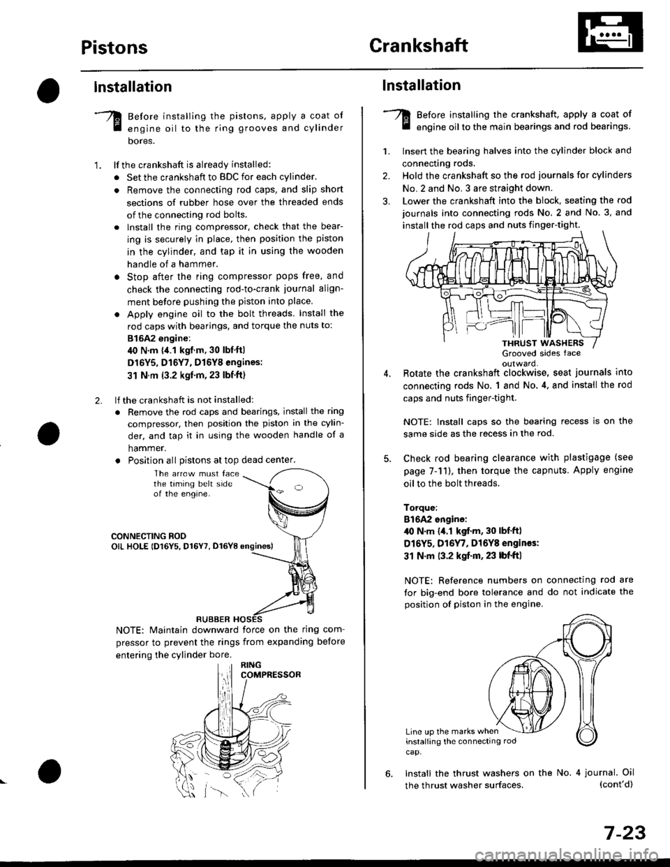
. Position all Distons at top dead center.
1.
2.
The arrcw must facethe taming belt sideof the engine.
CONNECTING ROOOIL HOLE lD16Y5, D16Y7, D16YB ongines)
NOTE: Maintain downward force on the ring com-
pressor to prevent the rings from expanding before
entering the cylinder bore.
RUBBER
,lll
lnstallation
Before installing the crankshaft, apply a coat of
engine oil to the main bearings and rod bearings.
Insert the bearing halves into the cylinder block and
connecting rods.
Hold the crankshaft so the rod journals for cylinders
No.2 and No. 3 are straight down.
Lower the crankshaft into the block, seating the rod
journals into connecting rods No. 2 and No. 3, and
install the rod caps and nuts finger-tight.
1.
2.
3.
5.
Grooved sides faceoulward.Botate the crankshaft clockwise, seat journals into
connecting rods No, 1 and No.4, and install the rod
caps and nuts finger-tight.
NOTE: Install caps so the bearing recess is on the
same side as the recess in the rod.
Check rod bearing clearance with plastigage (see
page 7-11), then torque the capnuts. Apply engine
oil to the bolt threads.
Torque:
816A2 sngine:/l{, N.m {a.l kgf.m, 30 lbf'ftl
D16Y5, D16Y7, Dl6Y8 engines:
31 N.m (3.2 kgf.m, 23 lbf'ft|
NOTE: Reference numbers on connecting rod are
for big-end bore tolerance and do not indicate the
position of piston in the engine.
Line up the marks wheninstalling the connectrng rod
cap.
6. Install the thrust washers on the No. 4 journal. Oil(cont'd)
7-23
the thrust washer surfaces,
Page 682 of 2189
Description
(cont'dl
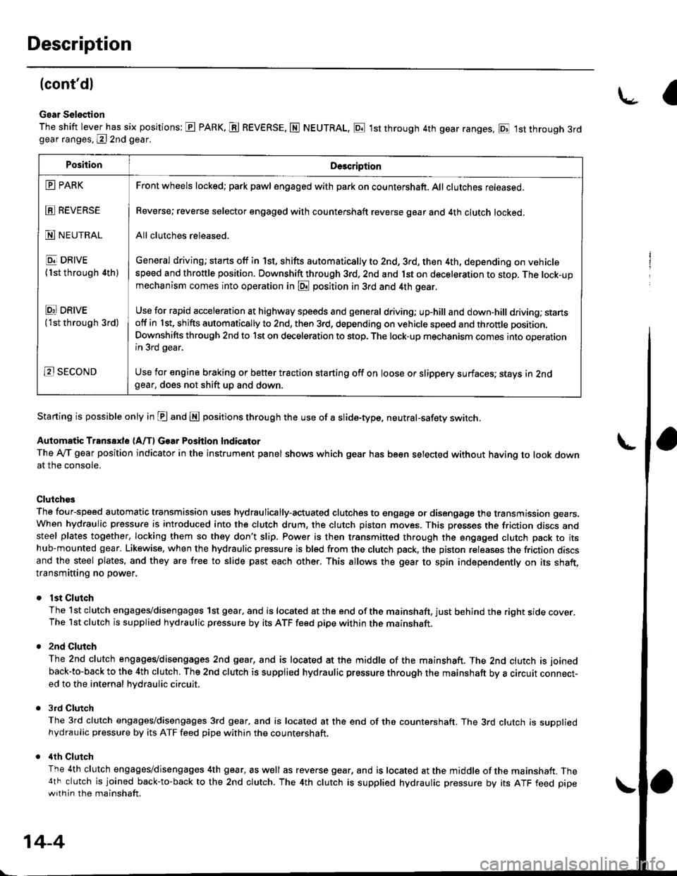
Gear Selection
The shift lever has six positions: E PARK. E REVERSE, N NEUTRAL, E 1st through 4th gear ranges, E 1st through 3rdgear ranges, @ 2nd gear.
Starting is possible only in E and E positions through the use of a slide-type, neutral-safety switch.
Automatic Transaxle (A/f, Gear Position Indicator
The Ay'T gear position indicator in the instrument panel shows which gear has been selected without having to look downat the console.
Clutch€s
The four-speed automatic transmission uses hydraulically-actuated clutches to engage or disengage the transmission gears.When hydraulic pressure is introduced into the clutch drum, the clutch piston moves. This presses the friction discs andsteel plates together, locking them so they don't slip. Power is then transmitted through the engaged clutch pack to itshub-mounted gear. Likewise, when the hydraulic pressure is bled from the clutch pack, the piston releases the friction discsand the steel plates, and they are free to slide past each other. This allows the gear to spin independently on its shaft,transmitting no power.
lst Clutch
The 1st clutch engages/disengages 1st gear, and is located at the end of the mainshaft, just behind the right sroe cover.The 1st clutch is supplied hydraulic pressure by its ATF feed pipe within the mainshaft.
2nd Clulch
The 2nd clutch engagegdisengages 2nd gear, and is located at the middle of the mainshaft. The 2nd clutch is joined
back-to-back to the 4th clutch. The 2nd clutch is supplied hydraulic pressure through the mainshaft by a circutr connect-ed to the internal hvdraulic circuit,
3rd Clutch
The 3rd clutch engages/disengages 3rd gear, and is located at the end of the countershaft. The 3rd clutch is suooliedhydraulic pressure by its ATF feed pipe within the countershaft.
ilth Clutch
The 4th clutch engages/disengages 4th gear, as well as reverse gear, and is located at the middle of the mainshaft. The4th clutch is joined back-to-back to the 2nd clutch. The 4th clutch is supplied hydraulic pressure by its ATF feed pipewith in the mainshaft.
\-a
PositionDe3cription
E PARK
E REVERSE
N NEUTRAL
E DRIVE
{1st through 4th)
Ei DRtvE('lst through 3rd)
B SECOND
Front wheels locked; park pawl engaged with pa* on countershaft. All clutches released.
Reverse; reverse selector engaged with countershaft reverse gear and 4th clutch locked.
All clutches released.
General driving; starts off in 1st, shifts automatically to 2nd, 3rd, then 4th, depending on vehiclespeed and throttle position. Downshift through 3rd, 2nd and 1st on deceleration to stop. The lock-upmechanism comes into operation in @ position in 3rd and 4th gear.
Use for rapid acceleration at highway speeds and general driving; up-hill and down,hill dfiving; stansotf in 1st, shifts automatically to 2nd, then 3rd, depending on vehicle speed and throttle position.
Downshifts through 2nd to lst on deceleration to stop. The lock-up mechanism comes into operationin 3rd gear,
Use for engine braking or better traction starting off on loose or slippery surfaces; stays in 2ndgear, does not shift up and down.
14-4
Page 876 of 2189

Description
Clutches/Reverse Brake/Planetary Gear/Pulleys
Clulches/Reverse Brake
The CVT uses the hydraulically-actuated clutches and brake to engage or disengage the transmission gears. When
hydraulic pressure is introduced into the clutch drum and the reverse brake piston cavity, the clutch piston and the reverse
brake piston move. This presses the friction djscs and the steel plates together, locking them so they don't slip. Power is
then transmitted through the engaged clutch pack to its hub-mounted gear. and through engaged ring gear to pinion
gears.
Likewise, when the hydraulic pressure is bled from the clutch pack and the reverse brake piston cavity, the piston releases
the friction discs and the steel plates, and they are free to slide past each. This allows the gear to spin independently on its
shaft, transmitting no power.
Start Clutch
The start clutch, which is located at the end of the driven pulley shaft, engages/disengages the secondary drive gear.
The start clutch is supplied hydraulic pressure by its ATF feed pipes within the driven pulley shaft.
Forward Clutch
The forward clutch, which is located at the end of the drive pulley shaft, engages/disengages the sun gear.
The forward clutch is supplied hydraulic pressure by its ATF feed pipe within the drive pulley shaft.
Reverse Brake
The reverse brake, which is located inside the inte.mediate housing around the ring gear, locks the ring gear in E posi-
tion. The reverse brake discs are mounted to the ring gear and the reverse brake plates are mounted to the intermediate
housing. The reverse brake is supplied hydraulic pressure by a circuit connected to the internal hydraulic circuit.
Planetary Gear
The planetary gear consists of a sun gear, a carrier assembly, and a ring gear. The sun gear is connected to the input shaft
with splines. The pinion gears are mounted to the carrier which is mounted to the fo.ward clutch drum. The sun gear
inputs the engine power via the input shaft to the planetary gear, and the carrier outputs the engine power. The ring gear
is only used for switching the rotation direction of the pullev shafts,
In E. E, and E positions (forward range), the pinion gears don't rotate and revolve with the sun gear, so the carrier
rotates. In E] positjon {reverse range), the reverse brake locks the ring gear and the sun gear drives the pinion gears to
rotate. The pinion gears rotate and revolve in the opposite direction from the rotation direction of the sun gear, and the
carrier rotates with pinion gear revolution.
Pulleys
Each pulley consists of a movable face and a fixed face, and the effective pulley .atio changes with engine speed. The
drive pulley and the driven pulley are linked by the steel belt.
To achieve a low pulley ratio, high hydraulic pressure works on the movable face of the driven pulley and reduces the
effective diameter of the drive pulley. and a lower hydraulic pressure works on the movable face of the drive pulley to
eliminate the steel belt slippage. To achieve a high pulley ratio, high hydraulic pressure works on the movable face of the
drive pulley and reduces the eifective diameter of the driven pulley, and a lower hydraulic pressure works on the movable
face of the driven pulley to eliminate the steel belt slippage.
b
14-198
Page 1176 of 2189
Master Cylinder/Brake Booster
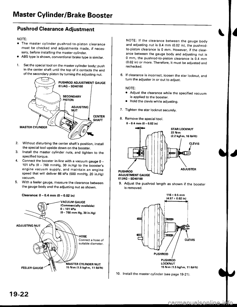
Pushrod Glearance Adjustment
NOTEr
. The master cylinder pushrod-to-piston clearancemust be checked and adjustments made, if neces_sary, before installing the master cylinder.. ABS type is shown, conventional brake type is similar.
1. Set the special tool on the master cylinde. body; push
in the center shaft until the top of it contacts the endofthe secondary piston by turning the adjusting nut.
Without disturbing the center shaft's Dosition, installthe specialtool upside down on the booster.Install the master cylinder nuts, and tighten to thespecified torque.
Connect the booster in-line with a vacuum gauge O _
101 kPa (0 - 760 mmHg, 30 in.Hg) to the booster,sengine vacuum supply, and maintain an enginespeed that will deliver 66 kpa (500 mmHg, 20 in.Hg)vacuum.
With a feeler gauge. measure the clearance Detweenthe gauge body and the adjusting nut as shown.
Clearance: 0 - 0.4 mm {0 - 0.02 in)
VACUUM GAUGE(Comm€rcially availeblel0 - 101 kPa{0 - 760 mm Hg, 30 in.Hg)
AOJUSTING NUT
FEELER GAUGE
19-22
10.
NOTE: lf the clearance between the gauge bodyand adjusting nut is 0.4 mm (0.02 in), the pushrod-to-piston clearance is 0 mm. However, if the clear_ance between the gauge body and adjusting nut is0 mm, the pushrod-to-piston clearance is 0.4 mm(0.02 in) or more. Therefore, it must be adjusted andrechecked.
6. lf clearance is incorrect, loosen the star locknut, andturn the adjuster in or out to adjust.
NOTE;
. Adjust the clearance while the specified vacuumis applied to the booster.. Hold the clevis while adjusting.
Tighten the star locknut securely.
Remove the special tool.
0 - 0.4 mm (0 - 0.02 in)
7.
ADJUSTERPUSHRODADJUSTMENT GAUGE07JAG - SD('1(x)
9. Adjust the pushrod length as shown if the boosterrs removed.
STAR LOCKNUT22 N.m{2.2 kg,f.m, 16lbtft)
11610.5 mm{{.571 0.02 in)
PUSHRODLOCKNUT15 N.m 11.5 kgf.m, 11 tbtftl
Install the master cylinder {see page l9-21).