1998 HONDA CIVIC Ignition coil
[x] Cancel search: Ignition coilPage 1581 of 2189
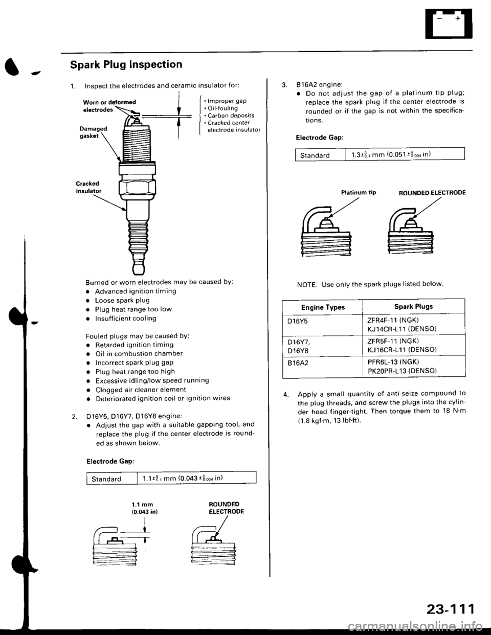
1. Inspect the electrodes and ceramic insulator for:
Spark Plug lnspection
Crackedinsulator
2.
[ . t.p,op", grp
| . Oil-fouling
i . Carbon deposits
| . Cracked center
I electrode insulator
Burned or worn electrodes may be causecl by:
. Advanced ignition timing
. Loose spark plug
. Plug heat range too low
. Insufficient cooling
Fouled plugs may be caused bY:
. Retarded ignition timang
. Oil in combustion chamber
. Incorrect spark plug gap
. Plug heat rangetoo high
. Excessive idling/low speed running
. Clogged air cleaner element
. Deteriorated ignition coil or ignition wares
D16Y5, D16Y7, D'16Y8 enginel
. Adjust the gap with a suitable gapping tool, and
replace the plug il the center electrode is round-
ed as shown below.
Electrode Gap:
1.1 mm
{o.{X:l in)ROUNDEDELECTRODE
Standard 1.1r8 ' mm (0.043i800oin)
Worn or detormed
1T
23-111
3. 816A2 engine:
. Do not adjust the gap of a platinum tip plug;
replace the spark plug il the center electrode is
rounded or it the gap is not within the specifica
tro ns.
Electlode Gap:
Standard 1.3181mm (0.051 !3oo" in)
flOUNDED ELECTROOE
',/
@_
:
Platinum tip
NOTE: Use only the spark plugs listed below
4. Apply a small quantity of anti seize compound to
the plug threads, and screw the plugs into the cylin
der head finger-tight. Then torque them to 18 N m
11.8 kgf.m, 13lbnft).
Engine TypesSpark Plugs
D16Y5ZFR4F 11 (NGK)
KJ14CR-111 (DENSOi
D16Y7,
D,I6Y8
ZFRSF-11 (NGK)
KJ16CR-111(DENSO)
81642PFR6L.13 (NGK)
PK2OPR.L13 (DENSO}
Page 1612 of 2189
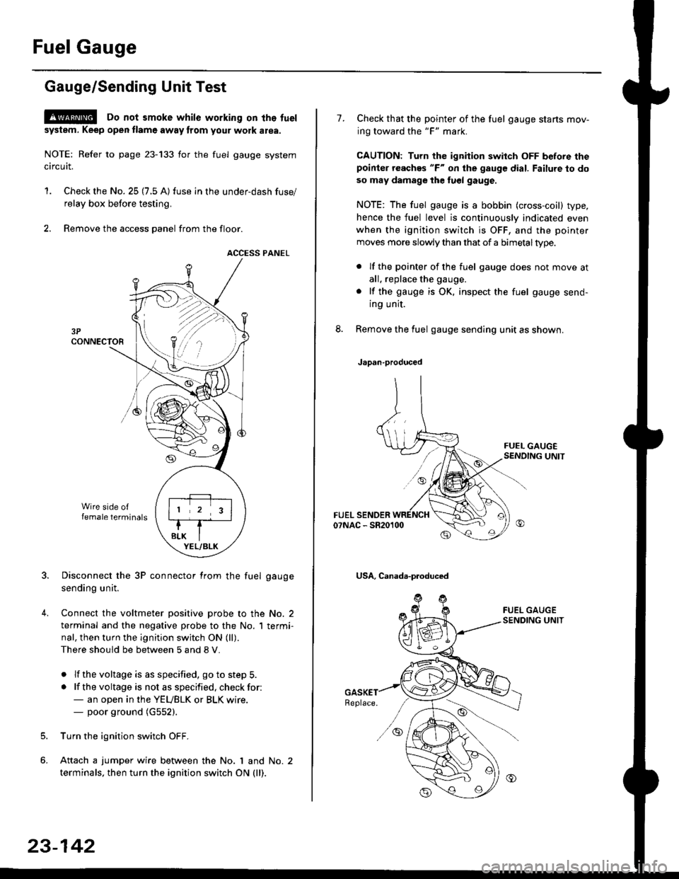
Fuel Gauge
Gauge/Sending Unit Test
!@ Do not smoke while working on tho fuel
system. Keep open tlame away trom your wotk atea.
NOTE: Refer to page 23-133 for the fuel gauge system
circuit.
'1. Check the No. 25 (7.5 A) fuse in the under-dash fuse/
relay box before testing.
2. Remove the access panel from the floor.
ACCESS PANEL
Disconnect the 3P connector from the fuel gauge
sending unit.
Connect the voltmeter positive probe to the No. 2
terminal and the negative probe to the No. I termi-
nal, then turn the ignition switch ON (ll).
There should be between 5 and 8 V.
. lf the voltage is as specified, go to step 5.
. lf the voltage is not as specified. check for:- an open in the YEUBLK or BLK wire.- poor ground (G552).
Turn the ignition switch OFF.
Attach a jumper wire between the No. 1 and No. 2
terminals, then turn the ignition switch ON (ll).
)\
23-142
1.Check that the pointer of the fuel gauge starts mov-
ing toward the "F" mark.
CAUTION: Turn the ignition switch OFF before thepoinier reaches "F" on ihe gauge dial. Failure to do
so may damage the fuel gauge.
NOTE: The fuel gauge is a bobbin (cross-coil) type,
hence the fuel level is continuously indicated even
when the ignition switch is OFF, and the pointer
moves more slowly than that of a bimetaltype.
. lf the pointer of the fuel gauge does not move at
all, replace the gauge.
. lf the gauge is OK. inspect the fuel gauge send-
ing unit.
Remove the fuel gauge sending unit as shown.
Japan-produced
USA, Canada-produced
Page 1827 of 2189
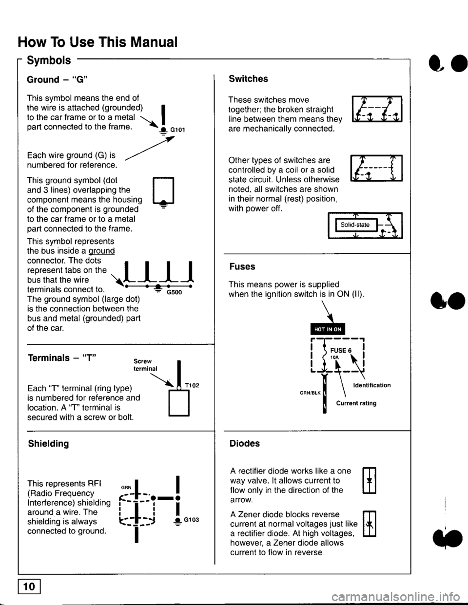
How To Use This Manual
Symbols
Ground - "G"
This symbol means the end ol
the wire is attached (grounded) Ito the car frame or to a metal I
part connected to the frame. \i oro,|
-t'
Each wire ground (G) it --/
numbered for reference.
oo
Switches
These switches move
together; the broken straight
line between them means the,
are mechanically connected.
Other types of switches are
controlled by a coil or a solid
state circuit. Unless otherwise
noted. all switches are shown
in their normal (rest) position,
with power off.
This ground symbol (dot
and 3 lines) overlapping the
component means the housing
of the component is grounded
to the car frame or to a metal
part connected to the frame.
This symbol represents
the bus inside a ground
connector. The dots I
i:l*,':1,'^:*,:"
;"
r"L I I I
terminals connect to.
The ground symbol (large dot)
is the connection between the
bus and metal (grounded) part
of the car.
Terminals - "T"
ffi
ffi
Solid-state
Fuses
This means power is supplied
when the ignition switch is in ON (ll).
Current rating
Diodes
A rectifier diode works like a one
way valve. lt allows current to
llow only in the direction of the
arrow.
A Zener diode blocks reverse
current at normal voltages just like
a rectifier diode. At high voltages.
however, a Zener diode allows
current to f low in reverse
oo
Each "T" lerminal (ring type)
is numbered for reference and
location. A "T" terminal is
secured with a screw or bolt.
Shielding
This represents RFI
(Radio Frequency
Interference) shielding
around a wire. The
shielding is always
connected to ground.
f--l;j-i",..
I
,,,,
T
Page 1957 of 2189
- How the Circuit Works
Battery voltage is supplied through tuse 56 to the
A,/C compressor clutch r€lay contacts at all times.
With the ignition switch in ON (ll), vollage is applied
to the coil of the A,/C compressor clutch relay
through fuse 17. When you push the A,/C switch
ON, and the heater fan switch is in position | , 2, 3,
or 4, a "ground" input is provided to the engine
control module (ECM) or powertrain control module
(PCM) through the l'lC thermostat and the l'lC
pressure switch.
The A,/C compressor clutch relay is grounded by the
engine control module (ECM) or powertrain control
module (PCM). When energized, the A'lC
compressor clutch relay allows battery voltage to
turn on the A,/C comDressor clutch.
The A,/C ON indicator light comes on when the A,/C
system is requested.
A,/C Thermostat
The A'lC thermostat is located on the evaoorator
housing. The A,/C thermostat turns off the A,/C
compressor clutch if the temperature at the
evaporator goes below 3'C (37'F). This prevents
condensation from freezing on the evaporator fins
and blocking the air delivery into the passenger
compartment. The blower motor will keep running
when the sensor turns off the comDressor.
A,/C Pressure Switch
The fuC oressure switch is located in the condenser
outlet line where refrigerant is in a high
temperature/high pressure liquid state. The switch
will sense abnormally high or low pressure, and
open the circuit. This removes ground, and the
compressor will stop running.
Thermal Protectot
The thermal protector, located on the A,/C
compressor, opens and turns the compressor off if it
senses high temperature. Once the compressor
cools, the switch will close and the compressor will
begin running again.
Refer to the Service Manual (Section 22,
Air Conditioning) for specific tests or
troubleshooting procedures.
62-3
Page 1961 of 2189
- How the Circuit Works
Radiator Fan
Voltage is provided at all times to the radiator fan
relay (contacts) through fuse 57. With the ignition
swilch in ON (ll), voltage is provided to the coil of
the relay through luse 17.
The radiator tan relay can be grounded through
either the engine coolant temperature switch or the
engine control module (ECM) or powertrain control
module (PCM).
The engine coolant temperature switch grounds
the radiator fan relay (coil) when the engine
coolant temperature exceeds 199'F (83'C). The
switch opens when coolanl temperature
decreases 3'- 8'C.
Condenser Fan
Voltage is provided at all times to the condenser fan
relay (contacts) through fuse 56. With the ignition
switch in ON (ll), voltage is provided to the coil of
the relay through fuse 17. When you push the A'lC
switch and put the heater fan switch in 1, 2,3, o( 4
position, the ly'C thermostat comes on, the
condenser fan relay energizes, and the condenser
fan motor runs.
A,/C Thermostat
The A,/C thermostat is located on the evaporator
housing. The A,/C thermostat tums off the A/C
compressor clutch if the temperature at the
evaporator goes below 3'C (37'F). This prevents
condensation from freezing on the evaporator fins
and blocking the air delivery into the passenger
compartment. lf the temperature goes below 3'C
(37"F) tuming off the Ay'C thermostat, ground will be
removed from the condenser fan relay. This will
deenergize the relay and remove voltage from the
condenser fan motor causing the fan to stop running.
Reter to the Service Manual (Section 23, Eleckical)
for specific tests or troubleshooting procedures.
63-3
Page 1964 of 2189
Rear Window Defogger
- How the Circuit Works
'96198 Models
Voltage is applied at all limes through tuse 50 to the
rear window detogger relay (contacts). With the
ignition switch in ON (ll), voltage is applied through
tuse 16 to the rear window defogger switch.
When you turn the switch ON, voltage is applied to
the defogger timer circuit. The timer circuit supplies
voltage to the rear window defogger relay (coil). The
relay energizes and supplies voltage to the rear
window defogger. The defogger grid then heats the
rear window to remove any condensation from the
glass.
The defogger timer circuit will automatically turn off
the rear window defogger after about 25 minutes.
Refer to the Service Manual (Section 23, Electrical)
for specific tests or troubleshooting procedures.
'99100 Models
Voltage is applied at all times through fuse 50 to the
rear window delogger relay (contacts). With lhe
ignition switch in ON (ll), voltage is applied through
fuse 16 to the heater control oanel.
When you turn the rear window defogger switch
ON, a signal is sent to lhe defogger timer circuit
built-into the heater control oanel. The timer circuit
supplies voltage to the rear window defogger relay
(coil). The relay energizes and supplies voltage to
the rear window defogger. The defogger grid then
heats the rear window to remove anv condensation
from the glass.
The defogger timer circuit will automatically turn otf
the rear window defogger after about 25 minutes.
Refer to the Seryice Manual (Section 23, Electrical)
for specific tesls or troubleshooting procedures.
64-2
I
a
a
Page 1980 of 2189
Gauges (cont'd)
- How the Gircuit Works
When the ignition switch is in ON (ll) or START (lll),
battery voltage is supplied through fuse 25 to the
gauges in the gauge assembly.
Speedometer and Odometer
The odometer and soeedometer drive circuits
receive pulses from the vehicle speed sensor
(VSS). The pulse rate increases as the car
accelerates. The frequency and duration of these
input pulses are measured and displayed by the
speedometer, odometer and tripmeter.
Tachometer
The tachometer drive circuit receives pulses from
the ignition control module (lCM) in the distributor
assembly or the ECM/PCM. The solid-state
lachometer then displays these pulses as engine
speed. For each 200 pulses per minute from the
ignition control modul€ (lCM) or the ECM/PCM, the
tachometer displays 100 RPM.
Engine Coolant Temperature Gauge
The engine coolant temperature gauge has two
intersecting coils wound around a permanent
magnet rotor. Voltage applied to the coils, through
fuse 25, generates a magnetic lield. The magnetic
field, controlled by the coolant temperature sending
unit, causes the rotor to rotate and the gauge
needle to move. As the resistance in the sending
unit varies, current through the gauge coils
changes. The gauge needle moves toward the coil
with the strongest magnetic field.
The 6ngine coolant temperature sending unit's
resistance varies from about 137 ohms at low
engine temperature to between 3H6 ohms at high
temperature (radiator fan running).
Refer to the Service Manual (Section 23, Electrical)
for specific tests or troubleshooting procedures.
81-2
(
Fuel Gauge (All except cX)
The fuel gauge has two intersecting coils wound
around a permanent magnet rotor. Voltage applied
to the coils, through tuse 25, generates a magnetic
field. The magnetic field, controlled by the fuel
gauge sending unit, causes the rotor to rotate and
the gauge needle to move. As the resislance in the
sending unit varies, current through the gauge coils
changes. The gauge needle moves toward the coil
with the strongest magnetic field.
The fuel gauge sending unit's resistance varies
from about 2-5 ohms at full, to about 110 ohms at
empty. When you turn the ignition switch off, the
gauge remains at the last reading until you turn the
ignition switch to ON (ll) or START (lll) again,
Refer to the Service Manual (Section 23, Electrical)
for specific tests or troubleshooting procedures.
Fuel Gauge (GX)
The fuel gauge has two intersecting coils wound
around a permanent magnet rotor. Voltage applied
to the coils, through fuse 25, generates a magnetic
field. The magnetic field, controlled by the PCM,
causes the rotor to rotate and the gauge needle to
move. The PCM calculates the gas quantity in the
fuel tank by using the fuel pressure value detected
by the tuel tank pressure sensor and the fuel
temperature value detected by the fuel tank
temperalure sensor, and outputs the signal to the
gauge assembly. The gauge needle moves toward
the coil with the strongest magnetic field.
When you turn the ignition switch off , the gauge
remains at the last reading until you turn the ignition
switch to ON (ll) or START (lll) again. When the
PCM detects a malfunction with the fuel pressure or
temperature, or detects a gas leak, the PCM
reduces the fuel meter to 0.
Refer to the Service Manual GX Supplement
(Section 11 , Fuel and Emissions) for specific tests
or troubleshooting procedures.
a
a
Page 2018 of 2189
Power Windows (contd)
- How the Circuit Works
CAUTION: You could iniure your arms, hands, or
fingers if you unintentionally switch the driver's
window to "automatic down" while working in
that door with the power on. Disconnect the
window switch conneclot or the battery when
working in the driver's door.
System Description
The operation of the power windows is controlled by
the main switch in the power window master switch.
When the main switch is in OFF, only the driver's door
window can be opened or closed. With the main
switch ON, all windows can be ooened or closed
either by swtches in the master panel, or swttches in
the doors. The driver's window switch also has an
automatic down mode which is tumed on by pushing
the switch down to its second oosition.
The power windows are driven by reversible motors.
Each motor is protect€d by a built-in circuit breaker.
lf the window switch is held on too long (with the
window obstructed, or after the window is fully up or
down), the circuit breaker opens the circuit. The
circuit breaker resets automaticallv as it cools.
Driver's Window
With the ignition switch in ON, voltage is provided to
the coil of the power window relay through fus€ 24.
The contacts of the power window relay close, and
voltage is applied to the driver's switch. When you
push the power window master switch to UP, voltage
is applied to the driver's window motor. (The motor's
ground path is back through the master power
window switch.) The driver's window motor then
drives the window up. When you push the switch to
DOWN, voltage is applied in the opposite direction
and the motor drives the window down.
Automatic Down (Driver's Window)
With the ignition switch in ON or START, voltage is
applied to the coil of the power window relay. The
contacts of the power window relay close and
voltage is applied lo the power window master
switch. When you push the driveas switch to the
AUTO DOWN position, voltage is applied through
the driver's switch to the driver's window motor. The
control unit receives pulses at the pulser input while
the motor is running. When the window is fully
down, the motor stops, and pulses are no longer
generated by the pulser. This is sensed by the
control unit at the pulser input, and voltage is no
longer applied to the driver's window motor.
Passenger Windows
With the ignition switch in ON, voltage is applied to
the coil of the power window relay through fuse 24.
The contacts of the power window relay then close,
applying voltage to the individual window switches
and the power window master switch. With the
master panel main switch ON, the passenger
windows can be ooerated from the individual
window switches or from tho master panel switches.
When you push the front passengsr's window
switch to UP, voltage is applied to the f ront
passenger's window motor. (The motor is grounded
through the contacts in the front passenger's
window switch and the oower window master
switch.) The window moves up as long as you hold
the switch in the UP position. lf you push the switch
to DOWN, voltage is applied in th€ opposite
direction to the front passenger's window motor, and
the window movss down as long as you hold the
switch in the DOWN Dosition. The window switches
in the other doors operate similarly.
When you push the front passenger's switch in the
master panel to UP, voltage is applied through the
front passenger's window switch contacts to the
front passengefs window motor. (The motor is
grounded through the contacts in the front
passenger's window switch and the power window
master switch.) The window moves up as long as
you hold the switch in the UP position. lf you push
the switch to DOWN, voltage is applied in the
opposite direction to lhe front passenger's window
motor, and the window moves down as long as you
hold the switch in the DOWN position. The other
passenger window switches in the master panel
operate similarly.
Refer to the Service Manual (Section 23, Electrical)
for specific tests or troubleshooting procedures.
120-4