1998 HONDA CIVIC Fan switch
[x] Cancel search: Fan switchPage 385 of 2189

PGM-FI System
(From page 11-115i{From page 11-115)
Chock to. poor response:1. Start the engine. Hold theengine at 3,000 rpm with M inE or E position, M/T in neutral untilthe radiator tan comeson, then turn the ignitionswitch OFF.2. Start the engine.3. Check the MAP with the scantool.
ls a N4AP ot 40.0 kPa {300 mmHg,12.0 in.Hg) or less indicated withinone second after staning theengine?
The MAP sensor is OK st this time.
Check lor poor response:1. Start the engine. Hold theengine at 3,000 rpm with M inE or E position, M/T in neu-tral until the radiator fan comeson, then turn the ignitionswitch OFF.2. Start the engine.3. Check the MAP with the scantool.
ls a MAP of 40.0 kPa (300 mmHg,12.0 in.Hg) or less indicated withinone second after starting theengine?
Substitute a known-good ECM/PCM and rechock. lt symptom/indication go6s .way. .6plrceth€ original ECM/PCM.
Manifold Absolute Pressure (MAP) Sensor ('96 Modelsl (cont'dl
11-116
Page 390 of 2189

!Manifold Absolute Pressure (MAPI Sensor -
i;idlga lil;dels,'99 - 00 Dl6Y5 ensine with M/T)
ll
The scan tool indicates Diagnostrc Trouble code (DTC) Po108: A high voltage (low vacuum) problem in the
Manifold Absolute Pressure (MAP) sensor.
MAP SENSOR 3P CONNECTOR ICl11}
MAPIRED/GRNI
JUMPER WIRE
Wire side ol female terminals
vcclIYEL/RED)
ECM/PCM CONNECTOR D (16PI
MAP(RED/GRN)
sG1(GRN/WHT)
Wire side of female terminals
(cont'd)
11-121
The MIL has been reported on
OTC m108 is stolod.
Problem vetitication:
1. Start the engine. Hold the
engine at 3,000 rPm with no
load (in Park or neutral) until
the radiator fan comes on, then
let it idle.
2. Check the MAP with the scan
tool.
lntormittent lailure, sFtom k OK
.t thb time. Chock lor Poor con'
nections or loorg wires at Cll'l
|MAP sensorl snd ECM/PCM.
ls 101 kPa (760 mmHg,30 0 in.Hg)
or higher indicated?
Check tor an open in the MAP
36nSOt:1. Turn the ignition switch OFF
2. Disconnect the MAP sensor
3P connector.3. Install a jumper wire betlveen
the MAP sensor 3P connector
terminals No 3and No 2.
4. Turn the ignition switch ON (ll).
5. Check the MAP with the scan
tool.
ls 101 kPa (760 mmHg, 30 0 in.Hg)
or higher indicated?
Check for an open in wire (SG1
line):1. Remove the iumper wire.
2. Measure voltage between the
MAP sensor 3P connector te.
minals No. 1 and No 2
Rapai. open in the wito batwoen
ECM/PCM (D12) .nd MAP !en.or.ls there approx. 5 V?
Check for an oPon in the wiie
(MAP linel:1. Turn the ignition switch OFF.
2. Connect the ECM/PCM con-
nector terminals D3 and D12
with a iumPer wire.
3. Turn the ignition switch ON (ll).
4. Check the MAP with the scan
tool.
Repair opon in the wiles bstlt oon
ECM/PCM (D3l and MAP 3oGor.ls 101 kPa (760 mmHg, 30 0 in.Hg)
or higher indicated?
Substituto a known'good ECM/
PCM and rochock. ll normal MAP
is indicated, replace tho original
ECM/PCM.
JUMPER WIRE
lr,
Page 391 of 2189

PGM-FI System
Manifold Absolute Pressure (MAPI Sensor
11-122
('99 - 00 Models except D16YS engine with M/T) (contd)
The scan tool indicates Diagnostic Trouble Code (DTC) P0108: A high voltage flow vacuum) problem in theManifold Absolute Pfessure (MAp) sensor,
MAP SENSOR 3P CONNECTOR (C111I
MAPIRED/GRNI
Wire side of female terminals
vcclIYEL/RED)
ECM/PCM CONNECTOR C (31PI
JUMPER WIRE
Wire side of female terminals
Tho MIL has boon rcDortod on.DTC ml 08 b stolod.
Problem verification:'1. Start the engine. Hold theengine at 3,000 rpm with noload (in Park or neutral) untilthe radiator fan comes on, thenlet it idle.2. Check the MAP with the scantoot,
Intormittent f.ilu.e, rystom is OXat thi! time. Chock tor poor con-n6ction3 or looso wirea at C111(MAP 3en.or) and tho ECM/PC-M.
ls 101 kPa (760 mmHg.30in.Hg) or higher indicated?
Check for an open in the MAPaon5('r:1. Turn the ignalion switch OFF.2. Disconnect the MAP sensor3P connector.3. Install a jumper wire betwesnthe MAP sensor 3P conn6ctorterminals No.3 and No.2.4. Turn the ignition switch ON {ll).5. Check the MAP with the scantool.
ls 101 kPa (760 mmHg, 30in.Hg) or higher indicated?
Check fo. an opcn in wiro (SGlline):1. Removo the jumper wire.2. Measure voltage between theMAP sonsor 3P connector terminals No. 1 and No.2.
Roprir opon in tha wiJo bctwoenthc ECM/FCM (C7l rnd the MApsonln t.
ls there approx. 5 V?
Chsck for an open in tho wi.e{MAP lino}:1. Turn the ignition switch OFF.2. Install a jumper wire on theECM/PCM connectors betweenC7 and C17.3. Turn the ignition switch ON (ll).4. Check the MAP with the scantool,
Repair op€n in the wir6a bstwoontho ECM/FCM (C171 and rh6 MApscnltoa.
ls 101 kPa (760 mmHg, 30in.Hg) or higher indicated?
Substituto a known-good ECM/PCM and rechcck, It normal MAPis indiceted. r.place tho originalECM/PCM.
JUMPER WIRE
--
Page 392 of 2189

L
Manifold Absolute Pressure (MAP) Sensor (cont'dl
The scan tool indicates Diagnostic Trouble code (DTc) P1128: Manifold Absolute Pressure (MAP) lower than
exoected.
The scan tool indicates Diagnostic Trouble code (DTC) P1129: Manifold Absolute Pressure {MAP) higher than
exoected,
- Tho MIL has been t€Ported on.- DTC P1128 is stored.
Problem verification:1. Turn the ignition switch ON (ll).
2. Check the MAP with the scan
tool.
lntermitteni failu.e, sYstom i! OK
at thb time.ls 54.1 kPa (406 mm Hg, 16.0
in. Hg) or higher indicated?
- The MIL has been roported on.- DTC P1129 is slorod
Problem v6rilicaiion:1. Start the engine. Hold the
engine at 3,000 rpm with no
load (in Park or neutral) until
the radiator fan comes on,
then let it idle.
2. Check the MAP with the scan
tool.
Int6rmittent failuto, sy3tem i3 OK
at thi3 time.ls 43.3 kPa (325 mm Hg, 12 8
in. Hg)or less indicated?
11-123
Page 403 of 2189

PGM-FI System
Throttle Position (TPl Sensor ('99 - 00 Models except D16Y5 engine with M/T)
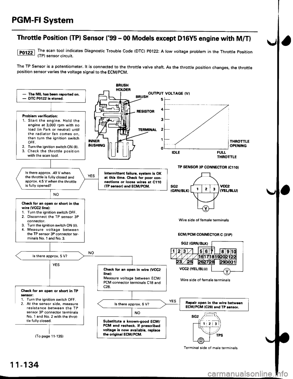
lTO12Z _TI scan tool indicates Diaqnosttc Trouble Code (DTC) P0122: A low voltage problem in the Throttle position- { | r, sensoa crrcurl.
The TP Sensor is a potantiometer. lt is connected to the throttle valve shaft. As the throttle position changes, the throttleposition sensor varies the voltage signal to the ECM/PCM.
ERUSHHOI.DENOUTPUT VOLTAGE (VIBRUSH
BESIS?OF
TERi'I AL
5
4
3
2
1
o
INNERBUS}IINGTHROTTLEOPE II{G
FULLTHROTTLE
TP SENSOR 3P CONNECTOR {Cl1OI
sG2IGRN/8LKIvcc2(YEUBLUI
Wire side of temale terminals
ECM/PCM OONNECTOR C 131P)
Ch.Gk for rn opan or 3hort in TP36nlot:1. Turn the ignition switch OFF.2, At the sensor side, moasureresistance between the TPsensor 3P connector terminalsNo. 1 and No. 2 with th€ throt,tle fully closed.
(To page 11-135)
- Th. MIL har boon.6portcd on.- DTC P0122 b siored.
Problem verification:1. Start the engine, Hold theengine at 3,000 rpm with noload (in Park or neutral) untilthe radiator fan comes on.then turn the ignition switchOFF,2. Turn the ignition switch ON (ll).3. Check the throttle positionwith the scan tool.
ls there approx. .49 V whenthe throttle is fully clos€d andapprox, 4.5 V when the throttleis fully opened?
l||t rmittont failura, lyrtom b OKat thi! tima. Chock tor poor con-nactionr o. looao wires rt C110{TP 3.n!or} rnd ECM/PCM.
Check for an opan or 3hort in thowi.c (VCC2 linc):1. Turn the ignition switch OFF.2. Disconnect the TP sensor 3Pconnector,3. Turn the ignition switch ON (ll).4. Measure voltago betweenthe TP sensor 3P connector terminals No. 1 and No.3.
ls thero approx. 5 V?
Chccl tor .n opln in wiro IVCC2lin€l:Mgasure voltago between ECM/PCM connector terminals C18 and
R.prir opcn in the wiro bctw.enECM/PCM (C281 and TP 3€nror.ls there approx. 5 V?
Subrtituto r known-good ECM/PCM .nd rochcck. lf pro.c.ibedvoltaga i! now available, roplacotho origin.l ECM/PCM.
Wire side ol female terminrls
Terminal side of male terminals
11-134
L
Page 406 of 2189

I
Throttle Position (TP) Sensor ('�99 - 00 Models except D16Y5 engine with M/Tl
The scan tool indicates Diagnostic Trouble Code {DTC) P0123: A high voltage problem in the Throftle Position
{TP) sensor circuit.
TP SENSOR 3P CONNECTOR {C11OI
sG2{GRN/BLKIvoc2
{YEUBLU}
'l'Wire side of female term;nals
ECM/PCM CONNECTOR C (31PI
Wire side of femal€ terminals
(cont'd)
11-137
The MIL has been reported on
DTC P0123 is slored.
Problem verification:1. Start the engine. Hold the
engine at 3,000 rpm with no
load (in Park or neutral) until
the radiator fan comes on
then turn the ignition swatch
OFF,2. Turn the;gnition switch ON (ll).
3. Check the throttle Positionwith the scan tool.
lntormittenl tailure, 3ystom is OK
at this time. Check tor Poor con'
neqtions or loo3€ wires at C'110(TP sensorl tnd ECM/PCM.
ls there approx. 10% when the
throttle is fully closed and
approx. 90% when the throttleis fully opened?
Ch€ck for an open in the TP s6n-
soJ:1. Turn the ignition switch OFF.
2. Disconnect the TP sensor 3P
3. Turn the ignition switch ON (ll).
4. At the wire harness side, mea-
sure voltage between the TP
sensor 3P connector terminalsNo. 1 and No.3.
ls there approx. 5 V?
Check tor an open in the wire(SG2lino):
Measure voltage between ECM/
PCM connector C (31Pi terminals
C18 and C28.
Repair open in the wite betwe€nECM/PCM (Cl81and TP son.or.ls there approx. 5 V?
Substitute a known-good ECM/PCM and recheck. lf Pr$cribedvoltage is now aveilabl6. replacethe original ECM/PCM.
Page 412 of 2189

Primary Heated Oxygen Sensor (Primary HO2SI (Sensor 1)
('96 - 9b Models except Dl6Y5 engine with M/Tl
PHO29IWHT}
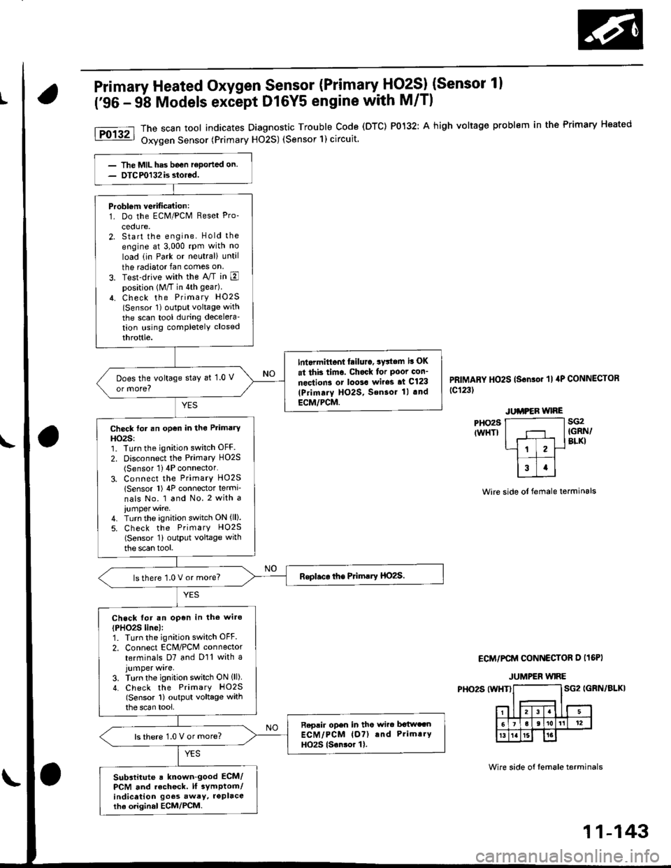
The scan tool indicates Diagnostic Trouble Code (DTC) P0132: A high voltage problem in the Primary Heated
Oxygen Sensor (Primary H02S) (Sensor'l) circuit.
PRIMARY HO2S (Sonso. 'll 4P CONNECToR
tc123t
sG2IGRN/BLKI
Wire side ot female terminals
ECM/PCM CONNECTOR D I16PI
JUMPER WIRE
PHO2S (WHT}SG2 IGRN/BLKI
Wire side of tem6le terminals
Probl€m verification:1. Do the ECM/PCM Reset Pro-
cedure.2. Start the engine. Hold the
engine at 3,000 rpm with no
load (in Park or neutral) until
the radiator fan comes on
3. Test-drive with the A/T in Eposition (M/T in 4th gear)
4. Check the PrimarY HO2S(Sensor 1) oLltPut voltage with
the scan tool during decelera'tion using completely closed
throttle.
Int.rmittont fiilur., system it OK
at thb timo. Chock for Poot con-
nections or loo3a wir63 at Cl23
lPrimarY HO2S, SensoJ 1l .nd
ECM/PCM.
Does the voltage stay at 1.0 V
or more?
Check for an open in the Primary
HO2S:1. Turn the ignition switch OFF.
2. Disconnect the Primary HO2S(Sensor 1) 4P connector'
3. Connect the PrimarY HO25
lSensor l) 4P connector termi-
nals No. 1 and No. 2 with a
4. Turn the ignition switch ON (ll).
5. Check the PrimarY H02S(Sensor 1i outPut voltage with
the scan tool.
lsthere 1.0 V or more?
Check for an open in the wiro
{PHO2S line):1. Turn the ignition switch OFF.
2. Connect EcM/PcM connector
terminals D7 and D11 with ajumper wrre,3. Turn the ignition switch ON lll)4. Check the PrimarY HO2S(Sensor 1) output voltage withthe scan tool,
Replir open in tho wirc b€twccnECM/PCM lo?) and Prim!.Y
HO2S lsonsor 1).ls there 1.0 V or more?
Substitute a known-good ECM/PCM and recheck. lf 3ymptom/indicetion goos awey, roplacethe oliginal ECM/PCM.
11-143
Page 413 of 2189

PGM-FI System
Primary Heated Oxygen Sensor (Primary HO2SI (Sensor 1)
('99 - 00 Models except D16Y5 engine with M/T)
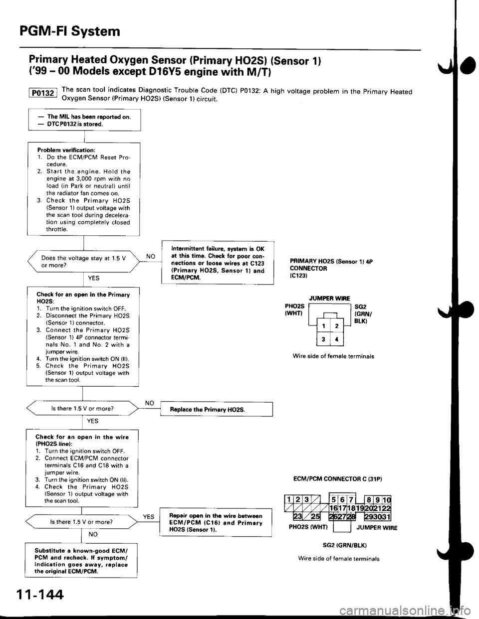
The scan tool indicates Diagnostic Trouble Code (DTC) P0132: A high voltage problem in the primary HeatedOxygen Sensor (Primary HO2S) {Sensor I ) circuit.
PRIMARY HO2S ls€n3or 1' 4PCONNECTOR(c123t
PHO2SIWHTI
Wire side of temale terminals
ECM/PCM CONNECTOR C 131PI
sG2(GRN/
BLK)
SG2 IGRN/8LK}
Ware side of female terminals
The MIL has been reported on.OTCP0132 is stored.
Problem vorificalion:1. Do the ECM/PCM Reset Procedure,Start the engine. Hold theengane at 3,000 rpm with noload (in Park or neutral) untilthe radiator fan comes on.Check the Primary HO25{Sensor lioutput voltage withthe scan tool during decelera-taon using completely closedthrottle.
Intermittent tailure, systom k OKat this time. Chock tor poor con-nections or looso wir* at Cl23(Primaly HO2S, Sonsor 1) andECM/PCM.
Check lor an open in the PrimaryH02S:1. Turn the ignition switch OFF.2. Disconnect the Primary HO2SlSensor 1)connector.3. Connect the Primary H02S(Sensor 1)4P connector terminals No. 1 and No. 2 with a
4. Turn the ignition switch ON (ll).5. Check the Primary H02S{Sensor l) output voltage withthe scan tool.
ls there 1.5 V or more?
Check lor an open in th€ wire(PHO25 lin€l:1. Turn the ignition switch OFF.2. Connect ECM/PCM connectorterminals C16 and C18 with ajumper wire.3. Turn the ignition switch ON {lli.4. Check the Primary HO2S(Sensor 1i output voltage withthe scan tool,
Roptir op.n in tho wire betweonECM/PCM lCl6l and Prim.ryHO2S lsensor 11.
ls there 1.5 V or more?
Subsiitute a known-good ECM/PCM and r.check. lf symptom/indication goos away, replecethe original ECM/PCM.
11-144