Page 1922 of 2189

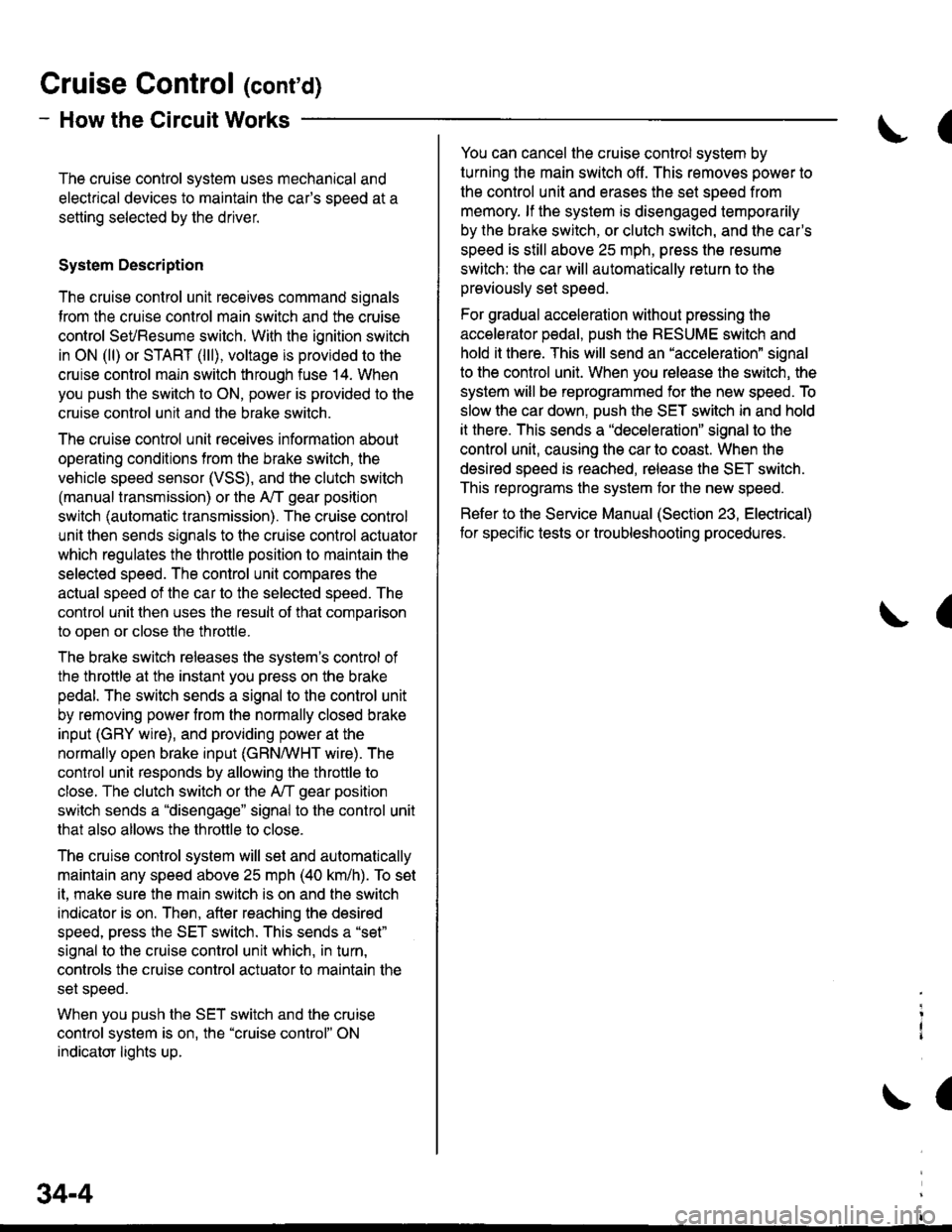
Gruise Control (cont'd)
- How the Circuit Works
The cruise control system uses mechanical and
electrical devices to maintain the car's sDeed at a
setting selected by the driver.
System Description
The cruise control unit receives command signals
from the crurse control main switch and the cruise
control SeVResume switch. With the ignition switch
in ON (ll) or START (lll), voltage is provided to the
cruise control main switch through fuse 14. When
you push the switch to ON, power is provided to the
cruise control unit and the brake switch.
The cruise control unit receives information about
operating conditions from the brake switch, the
vehicle speed sensor (VSS), and the clutch switch
(manual transmission) or the A,/T gear position
switch (automatic transmission). The cruise control
unit then sends signals to the cruise control actuator
which regulates the throttle position to maintain the
selected speed. The conlrol unit compares the
actual speed of the car to the selected speed. The
control unit then uses the result of that comoarison
to open or close the throttle.
The brake switch releases the system's control of
the throttle at the instant you press on the brake
pedal. The switch sends a signal to the control unit
by removing power from the normally closed brake
input (GRY wire), and providing power at the
normally open brake input (GRN/vVHT wire). The
control unit responds by allowing the throttle to
close. The clutch switch or the A,/T gear position
switch sends a "disengage" signal to the control unit
that also allows the throttle to close.
The cruise control system will set and automatically
maintain any speed above 25 mph (40 km/h). To set
it, make sure the main switch is on and the switch
indicator is on. Then, after reaching the desired
speed, press the SET switch. This sends a "set"
signal to the cruise control unit which, in turn,
controls the cruise control actuator to maintain the
set speed.
When you push the SET switch and the cruise
control system is on, the "cruise control" ON
indicator lights up.
34-4
(
You can cancel the cruise control system by
turning the main switch off . This removes power to
the control unit and erases the set speed from
memory. lf the system is disengaged temporarily
by the brake switch, or clutch switch, and the car's
speed is still above 25 mph, press the resume
switch: the car will automatically return to the
previously set speed.
For gradual acceleration without pressing the
accelerator pedal, push the RESUME switch and
hold it there. This will send an "acceleration" signal
to the control unit. When you release the switch, the
system will be reprogrammed for the new speed. To
slow the car down. oush the SET switch in and hold
it there. This sends a "deceleration" signal to the
control unit, causing the car to coast. When the
desired speed is reached, release the SET switch.
This reprograms the system tor the new speed.
Refer to the Service Manual (Section 23, Electrical)
tor specific tests or troubleshooting procedures.
(
a
Page 1926 of 2189
85'[ru*,, 'l*u,*
wiz-"ln*"
-a
I
le
.il
c131
vtEW 59
----sgr
c410
vlEw 35
LT GFN
12
LT GFN
-----1 A/T GOrr
GAUGE ASSEMBLYPHOTO 6/vlEw 71
I Posttlon
i Indlcator
I
I
I
I
I
I
IJ
14
\
I
I
II
A
I
I
I
I\
\
1
I
,
I
I
I
I
t
t
\
\
a)
S€e A,/TGearPositionIndicator
c4t0
vlEvl 35
'96 D16Y8 enqine: All Coupes'97 016Y7 engine: Calilornia Coupe,California Sedan LX'97 D16Yg engine: AllCoupes,California Sedan'98 model: All
'96 D16Y8 enqrne: All exceot CouDes'97 D16Y7 en6tne: All except CaliiorniaCoupe and Caftfornia Sedan LX'97 Dl6Y8 enginei All except Coupesand California Sedan
See A/TGearPositionlndicator
*"r I
-
----s+----+="1--'-scFN/AlU ll GRNryEL ll vEwar_----F----*-r nr cenn| | | POSITION| ; swlrcHt I oTo78
I
see cruise control I
{GBN/RED N'---1;'
'--T-)tn
39-3
Page 1930 of 2189
.I TRANSMISSION
I pa*l lcoNrRoLa noutral Reverso Driv€ inputs iMODULEI noutral Revelse lJriv€ inputi I MUuuLl-lilll'
! tarp pr) (aTpF) (Arp D) (ar" s) {ArP L) : Ploro^ t2'
;F"''^'*J l *l*|
.l
i{*m' vlEw 71
I
ll
,l
iatr=im*:l lJ l_L! !J
_____r| AJT G6ar
trJnl_
)a
\lseem l- caa,
I- Position
I I rrxrcaror
ll
tt
tlI .+----
3--{-----r----
" -T,[ i::I
"-1fi-*fiar+-!d
IFEOBII(BLU
r2A' ___ 14,{ ____134 _____Z_e______6i ____15"c_fJ^--oinir.-lf
i#fl''ucnNAVl{I ll GBN I GRN/REo ll GBN/ORN ll GBN/BLU lt GFNT'EL N rrtw.r,
{":-t{-8, 't'
I POSTTTONi swrTcHa PHO|O 78
r - - t- -- - - f -- - - - ? = - : - - - f - - - - -- r - - - - T - -t A,T GEaR
I
IJ
Page 1934 of 2189
POWERTRAINCONTROLMODULE(PCM)
t1fo 85'59
36 GX) rfo 142'20
= lrale-Female)rminals are also)versed on GX
-I POWET
I Parrv I c-oNrF
i l"=9"' l?v.9rse gll[gR'Y'
L-g-g-- Jg:l----i'11---iltP. ---:y!iii:;?""
::: I ::I ::I :1I :]:I
.-*1,*,. ",il**'*, ";l-i$;'r,,,. ,"*,f r,h,h.r::lnfft
:l*r*;'"1
l#+u"1
g_'" 9?,o;1"",.r n"n I
u't"" caucEAssE
nro I PI
SeeA/T GearPositionlndicator
*,, I
-l
See A,/TGearPositionlndicator
,nrt I
-
See !y'TC*arhsitionIndicator
A/T GoarPositionIndicaior
c410
V|EW35 WHT
o
13
GBN12GFNAVHI.! AiT GEARPOSTTIONSWITCH
See Cruise Control
39-11
Page 1938 of 2189
A9
LT GFr'l
12
LT GFN
A14
c410
vtEw 35
c131PHATA E5vtEw 59
D't 3
tT GRN/FED
15
GRN
See A./TGearPositionlndicator
"""L
c131
vtEw 59
WHT
GAUGEASSEMBLYPHO|O 67vtEw 71
See AfrGearPositionIndicator
wxr I
-
SeeArt GearPositionIndicator
"',, I
-l
I
lt
,l
tl
tt\
\
I
I
t
,,I
I
I
I
t
\
AII GsarPoclllonkldlcrtor
a
S€€ A/TGearPositionIndicator
Ii
fsn$t';
!d
c410
vtEw 35
c433
A/T GEARPOStTtONSWITCH
c433
BLKSee Gaounda-< Disaibdion,
| *o" to-t
"'*l
Y
t________l'--- -gcji-
PHOIO 125
--*
BLK
1
6LK
39-15
Page 1981 of 2189
A/T Gear Position Indicator
{\
-cw
@UNDER-DASHFUSE/RELAYBOX
r
See A/TControls
"Ttr
See Dash andConsole Lights
-AYlltFED I FED/BLK I
tl
YEL
A1
SEE A,TTControls,PGM.FI
I
;l
A/T GcarPoiltlo{|Indlc{or
GAUGEASSEMBLY
a\
t----Y---
BLKBLU
12
GRNA!/HT
c410
vtEw 35
BLKaLu
I
See A,/TControls
TI
:I
a
ta
A.t 3
BLKBLU
7
BLK/BLU
eui [SBruI
SeelnterlockSystem
I
;+
ar
l
-;-----;++
-l-rl
c433
A/TGEARPOStTtONswrTcH
Sec GroundDistribution,pag€ 1+7.
Y
I
I
aL__l+: G401
\
89
Page 1983 of 2189

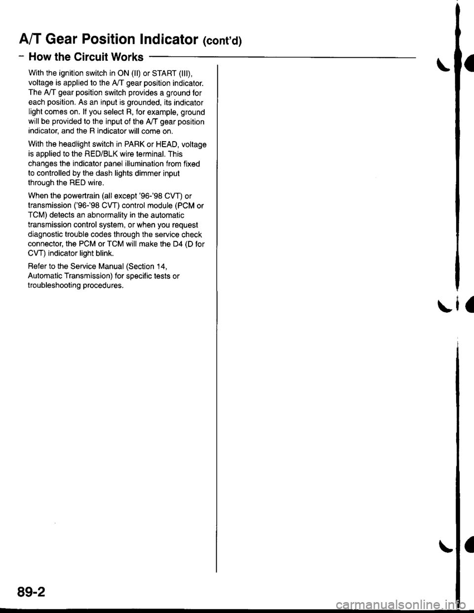
A/T Gear Position Indicator (conrd)
- How the Circuit Works
With the ignition switch in ON (ll) or START (lll),
voltage is applied to the A,/T gear position indicator.
The A,/T gear position switch provides a ground for
each position. As an input is grounded, its indicator
light comes on. lf you select R, for example, ground
will be provided to the input of the A,/T gear position
indicato( and the R indicator will come on.
With the headlight switch in PARK or HEAD, voltage
is applied to the RED/BLK wire terminal. This
changes the indicator panel illumination from fixed
to controlled by the dash lights dimmer input
through the RED wire.
When the powertrain (all except '96-'98 CVT) or
transmission ('96198 CVT) control module (PCM or
TCM) detects an abnormality in the automatic
transmission control system, or when you request
diagnostic trouble codes through the service check
connector, the PCM or TCM will make the D4 (D for
CVT) indicator light blink.
Refer to the Service Manual (Section 14,
Automatic Transmission) for specific tests or
troubleshooting procedures.
\ia
89-2
Page 2072 of 2189

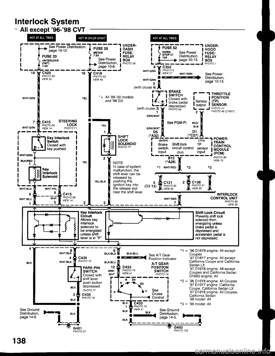
lnterlock System
- Allexcept'96-'98 CVT
page 10-12.
FUSE 33{INTEBLCICKuNrI)
WHIICRN
OASH I HOOD
H:" - IlEiE" i ) iifl* 8i?[',ffii i[".tfi
;GE-st----l glD^:R-
page 10-13. I BoxL.J------ --J PHotoi
*1 = 96 D16Y8 engine: Allexceptuoupes'97 D16Y7 engine: All exceptCalifornia Coupe and CaliforniaSedan LX'97 D16Y8 engine: All exceptCoupes and Calilornia SedanD1685 engine: All*2 = '96 D16Y8 engine: AllCoupes'97 D16Y7 engine: CaliforniaCoupe, California Sedan LX'97 D16Y8 englne: AllCoupes,Calilornia Sedan'98 model: All*3 = '99 model: All
)rq
,'",:[*nu'
=-CF'!,n:E!-l
Hfl*gff* i
l#?;"'" -,,;:::?i-ili:itlll:
|
= lr.u:;.Br-* i-{Ji6i1!-- !,*;L$il{:*
|
,wrn cruse;r
tr,
;"6;dii-- Lr7 r ii\l,B".i o,",,,
i-l o,"*",!
'""'o*-'' x?!
| -$-.",., .^AX-----.,'dtA--"^",."
lfl.iil F]iH*,"'i''t#'---.r=23[11
eowen.
lElJP-".'.'
-
L;tT'#:yTltijF.iu.'f, *or., ,.il3, f, iii"^'?o'
| !^:?::^?l:t:9" *r w'raeof, *2 *3
t:l*ii** ffi"""'"
! fit:'/:,:iffJff ,",'3,fii;1,1,'' 'trii'df,'
tr
I near lne snrn rever - TNTERLOCK
ll wxrneo t CONTROL UNIT
--4-------------Lt, *?,1fl92
T-----1 UNDER-FUSE 25
See Power I BOtDisilibution, : pHb'ro ss
.----
page 10-6. I 8 i, C352-----J' c419""'''A\Fi#"i: wHr/cRN see power
'[il:'ff*,,,,**
., J*:]l ., '"*""
;.-9,[ aL(BLU
GFN/
I
See A/T GearPosition Indicator
A/T GEARPOSITIONswtTcHc433
BLK I-
i-*t'
BLK1BLK
f, 9e€urutse
I
I
I
IControl
ilt:tfi'F1
'-i_:{BLKO-<(
See GroundDistribution,page 14-5.
-l#: G401PHO|O 57
Key IntedockClrcuitAllows keyint€rlocksolenoid tobe energizedunless shiftlever is in "P"
Shltt Lock ChcuilPrevents shifi bcksolenoid tromenergizing unlessbrake p€dal isd€pfessed ardacc€le{ator pedal isnot depr€ssed.
";t-,".f";,
138