1998 HONDA CIVIC ECU
[x] Cancel search: ECUPage 1746 of 2189
Precautions/Procedu res
SRS Unit Precautions
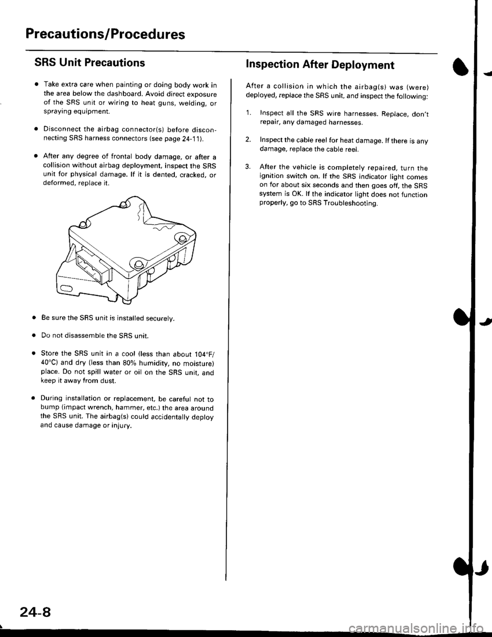
Take extra care when painting or doing body work inthe area below the dashboard. Avoid direct exDosureof the SRS unit or wiring to heat guns, welding. orsprayang equipment.
Disconnect the airbag connector(s) before discon-necting SRS harness connectors (see page24-1|1J.
After any degree of frontal body damage, or after acollision without airbag deployment, inspect the SRSunit for physical damage. lf it is dented. cracked, ordeformed, replace it.
Be sure the SRS unit is installed securely.
Do not disassemble the SRS unit.
Store the SRS unit in a cool (less than about 104.F/40"C) and dry (less than 80% humidity, no moisture)place. Do not spill water or oil on the SRS unit, andkeep it away from dust.
During installation or replacement, be careful not tobump (impact wrench, hammer, etc.) the area aroundthe SRS unit. The airbag(s) could accidentally deptoyand cause damage or injury.
24-8
Inspection After Deployment
After a collision ln which the airbag(s) was (were)
deployed, replace the SRS unit, and inspect the following:
1. Inspect all the SRS wire harnesses. Replace. don,trepair, any damaged harnesses.
2. Inspect the cable reel for heat damage. lf there is anydamage, replace the cable reel.
3. After the vehicle is completely repaired, turn theignition switch on. lf the SRS indicator light comeson for about six seconds and then goes off. the SRSsystem is OK. lf the indicator light does not functionproperly, go to SRS Troubleshooting.
Page 1747 of 2189
)
Wiring Precautions
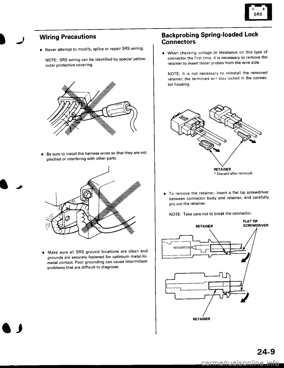
. Never attempt to modify, splice or repair SRS wiring'
NOTE: SRS wiring can be identified by special yellow
outer Protective covering.
8e sure to install the harness wires so that they are not
oinched or interfering with other parts.
t
Make sure all SRS ground locations are clean and
grounds are securely fastened for optimum metal-to-
metal contact. Poor grounding can cause intermittent
problems that are difficult to diagnose.
a,
24-9
Backprobing Spring'loaded Lock
Gonnectors
. When checking voltage or resistance on this type of
connector the flrst time, it is necessary to remove lne
retainer to insert tester probes from the wire side.
NOTE: lt is not necessary to reinstall the removed
retainer; the terminals wi I stay locked in the connec-
tor housrng.
To remove the retainer, insert a flat tip screwdriver
between connector body and retainer, and carefully
pry out the retainer.
NOTE: Take care not to break the connector.
FLAT TIPSCBEWDRIVER
RETAINER* Discard after removal.
RETAINER
Page 1753 of 2189
)Erasing the DTC Memory
To erase the DTC(s) from the SRS unit, use a Honda
PGM Tester (see the Honda PGM Tester SRS vehicle
System Supplement) or the following procedure
1. Make sure the ignition switch is OFF
2. Connect the SCS service connector to the MES con-
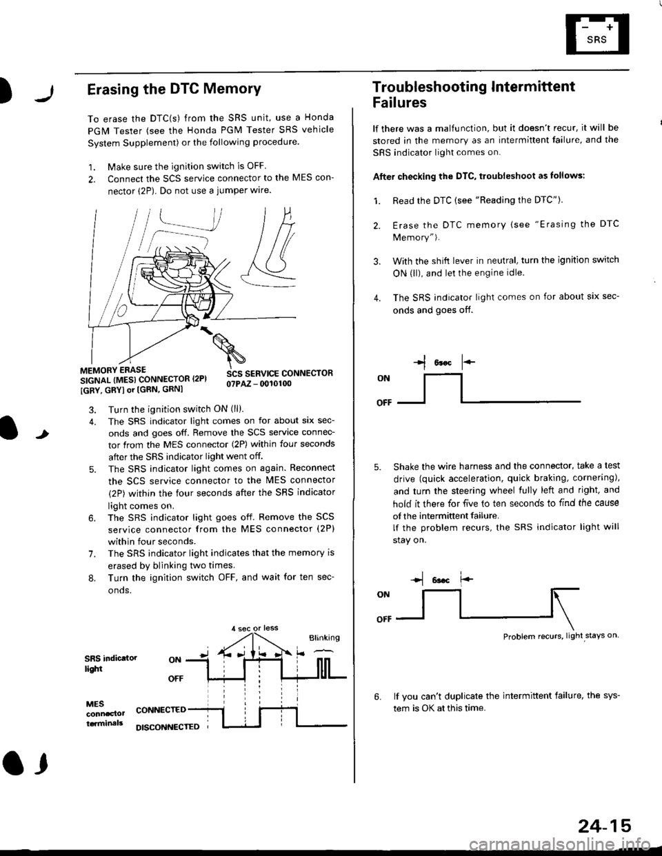
nector (2P). Do not use a jumper wlre.
]P,
&
.!--J
MEMORY ERASE
SIGNAL (MESI CONNECTOR I2PI
IGRY, GRYI or [GRN, GRNI
SCS SERVICE CONNECTORo?PAZ - 0010100
t
7.
Turn the ignition switch ON (ll).
The SRS indicator light comes on for about six sec-
onds and goes off. Remove the SCS service connec-
tor from the MES connector (2P) within four seconds
after the SRS indicator light went off.
The SRS indicator light comes on again. Reconnect
the SCS service connector to the lvlES connector
(2P) within the four seconds after the SRS indicator
light comes on.
The SRS indicator light goes off. Remove the SCS
service connector from the MES connector (2P)
within four seconds.
The SRS indicator light indicates that the memory is
erased by blinking two times.
Turn the ignition switch OFF, and wait for ten sec-
onos.
8.
SRS indictlorlighi
MESconncclottcaminals
CONNECTED
O,
DISCONI{ECTED
24-15
Troubleshooting Intermittent
Failures
lf there was a malfunction, but it doesn't recur, it will be
stored in the memory as an intermittent failure, and the
SRS indicator light comes on.
Afte. checking the DTC, troubleshoot as lollows:
1. Read rhe DTC {see "Reading the DTC"}.
Erase the DTC memory (see "Erasing the DTC
Memory").
With the shifi lever in neutral, turn the ignition switch
ON (ll), and lei the engine idle.
The SRS indicator light comes on for about six sec-
onds and goes off.
l*F
ON
tl-- -l
Shake the wire harness and the connector, take a test
drive (quick acceleration, quick braking, cornering),
and turn the steering wheel fully left and right, and
hold it there for five lo ten seconds to find the cause
of the intermittent failure.
lf the problem recurs, the SRS indicator light will
stay on.
-q 6a.c f'-
:q
Problem recurs, light stays on
3.
4.
6.lf vou can't duplicate the intermittent failure, the sys-
tem is OK at this time.
Page 1806 of 2189
Airbag
Replacement (cont'd)
Front Passenger's Side:
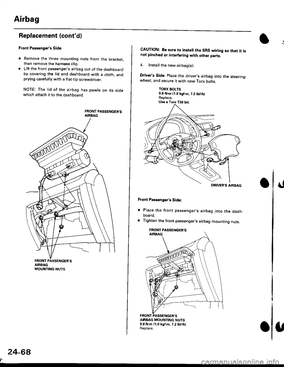
. Remove the three mounting nuts from the bracket,then remove the harngss clip.. Lift the front passenger's airbag out of the dashboardby covering the lid and dashboard with a cloth, andprying carefully with a flat-tip screwdflver.
NOTE: The lid of the airbag has pawls on its sidewhich attach it to the dashboard.
24-6a
CAUTION: B€ sure to inslall the SRS wiring so that it isnot pinched or interforirg with other parts.
4. Installthe new airbag(s):
Driver's Side: Place the driver,s airbag into the steeringwheel, and secure it with new Torx botrs.
TORX BOLTS9.E N.m (1,0 kgf.m, 7.2 tbt ftlReplace.
Front Pass€ngar's Side:
. Place the front passenger,s airbag into the dash-board.
. Tighten the front passenger,s airbag mounting nuts.
ANAAG MOUNTING NUTS9.8 N.m 11.0 kgf.m, 7.2lbf.frlReplace.
DRIVER'S AIRBAG
Page 1808 of 2189
Airbag
Disposal
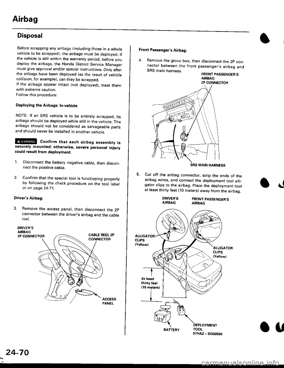
Before scrapping any airbags (including those in a wholevehicle to be scrapped), the airbags must be deployed. lfthe vehicle is still within the warranty period, before youdeploy the airbags, the Honda District Service Managermust give approval and/or special instructions. Onlv afterthe airbags have been deployed (as the result of vehiclecollision, for example), can they be scrapped.lf the airbags appear intact (not deployed). treat themwith extreme caution.
Follow this p.ocedure:
Deploying the Airbags: In.vehiclo
NOTE: lf an SRS vehicle is to be entirely scrapped, itsairbags should be deployed while still in the vehicle. Theairbags should not be considered as salvageable partsand should never be installed in another veh;cle.
!@ confirm thst oach airbag assembty issecurely mounted; otharwiso. sev€re personal iniurycould result lrom deployment.
1. Disconnect the baftery negative cable, then discon_nect the positive cable.
2. Confirm that the special tool is functioning properlyby following the check procedure on the tool labelor on page 24-'l'l .
Driver's Airbag:
3. Remove the access panel, then disconnect the 2pconnector between the driver,s airbag and the cablereet.
DRIVER'SAIRBAG2P CONNECTOR
24-70
BATTERY.U
Front Passenger's Airbag:
4. Remove the glove box, then disconnect the 2p con-nector between the lront passenger,s airbag andSRS main harness.FRONT PASSENGER'SAIREAG2P CONNECTOB
SRS MAIN HARNESS
Cut off the airbag connector, strip the ends of theairbag wires, and connect the deployment tool alli_gator clips to the airbag. place the deployment toolat least thirty feet (10 meters) away from the airbag.
a!
DRIVER'SAIRBAGFRONT PASSENGER'SAIRBAG
ALLIGACLIPS(Yellow)ALLIGATORCLIPS{Yellowl
At loastthiny toet(10 metorsl
Page 1809 of 2189
E-
)I
Connect a 12 volt battery to the tool:
. lf the green light on the tool comes on, the aar-
bag igniter circuit is defective and cannot deploy
the airbag. Go to Damaged Airbag Special
Procedure.
. lf the red light on the tool comes on, the airbag is
ready to be deployed.
Push the tool's deployment switch. The airbag
should deploY (deployment is both highly audible
and visible; a loud noise and rapid inflation of the
bag, followed by slow deflation).
. lf the airbags deploy and the green light on the
tool comes on. continue with this procedure.
. l{ an airbag doesn't deploy, yet the green light
comes ON, its igniter is defective. Go to Dam-
aged Airbag Special Procedure.
!!@ During doployment, the airbag sssom'
bly can become hot enough to buln you. Wait thir'
ty minutes aftsr deployment belore touching tho
assembly.
Dispose of the complete airbag assembly. No part
of it can be reused. Place it in a sturdy plastic bag,
and seal it securelY,
CAUTION:
. Wear a fsce shield and gloves when handling a
deployed airbag.
. Wash your hands and rinse them well with
wat6r after handling. deployed airbag.
t('
24-71
7.
AIRAAG
Doploying th6 Airbag: Out-of-vehicle
NOTE: lf an intact airbag has been removed from a
scrapped vehicle. or has been found defective or dam-
aged during transit, storage or service, it should be
deployed as follows:
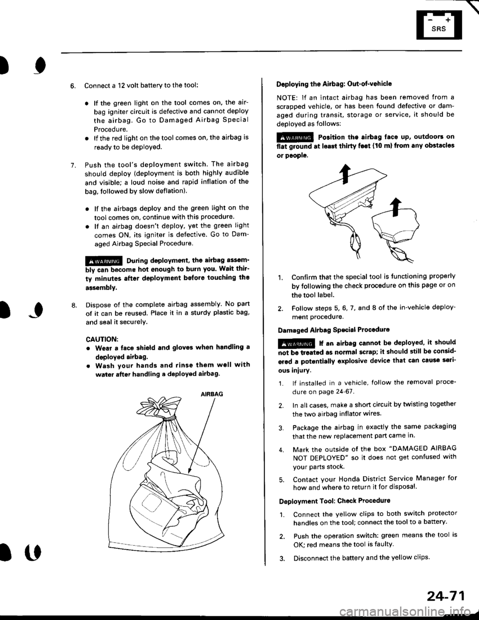
@ Po3ition the airbag laca up, outdoors on
flat ground at lsast thirty f€€t (t0 ml from any obstacles
or people.
1. Confirm that the special tool is tunctioning properly
by following the check procedure on this page or on
the tool label.
2. Follow steps 5, 6, 7, and I of the in-vehicle deploy-
menl Drocequre.
Damaged Airbag Spacial Procedure
!@ r an airb.g cannot be deployed, it should
iiiTi-treatcd as normal scrap; il should still be consid-
srsd a potontially oxplosive device that can cau3o ssti-
ous iniury.
1. lf installed in a vehicle, lollow the removal proce-
dure on page 24-67.
2. In all cases. make a short circuit by twisting together
the two airbag inflator wires.
3. Package the airbag in exactly the same packaging
that the new replacement part came in.
4. Mark the outside of the box "DAMAGED AIRBAG
NOT DEPLOYED" so it does not get confused with
your Parts stock.
5. Contact your Honda District Service Manager for
how and where to return it for disposal.
Deployment Tool: Check Procedur€
1. Connect the yellow clips to both switch protector
handles on the tool; connect the tool to a battery.
2. Push the operation switch: green means the tool is
OK: red means the tool is faulty
3. Disconnect the battery and the yellow clips.
Page 1817 of 2189

Contents
How to Use This Manual ICircuit Schematics (see Circuit Index)Fuse/Relaylnformation 6Ground-to-Componentslndex 6-6ComponentLocationPhotooraohs 201Conriector Views 202
Circuit Index
Accessory power socket 155Air conditionerAir delivery'96198 models 61'99-'00 models 61-2Blower controls'96198 models 60'99100 models 60-1Compressor controls 62Fans 63Anti-lock brake system (ABS) 44A/T gear position indicatorCVT 89All except CVT 89-1Automatic transmission controlsAll '96-'98 models except CVT and GX 39All '99100 models except CVT 39-8All GX models 39-8'96-'�98 CVT 39-4'99100 cw 39-12Back-up lightsCoupe and Sedan 110Hatchback l'10-1Brake lightsAll Coupes and'96-'98 Sedans 110-15'99-'00 Sedans 110-16Hatchback 110-17Brake system indicator light'96198 models 7'1'99100 models 71-1Ceiling light 114-3Charging system 22Condenser fan 63Console lights 114Cruise control 34Dash lights 114Daytime running lights 110- 13Engine coolant temperature gauge 81-1Fog lights 110-10Front parking lights 110-2Fuel gauge 81-1Fuse/relay boxUnder-dash 6Under-hood 6-4Underhood ABS 6-3Gauges 81Ground distribution 14Ground-to-Componentslndex 6-6Hazard warning lightsAll except '99100 Sedans 110-6'99100 Sedans 110-8Headlights 110-12Headlight switch 100Heater - See Air ConditionerHorn'96197 models 40'98 model 40-1'99100 models 40-2lgnition key reminder 73lgnition systemAll '96198 models except Dl685 20All '99100 models except D16Y5 with Mn 2O-2All D1685 engines 20-2'99-'00 D 16Y5 with M/T 20
lndicators 80Integrated control unit 70lnterlock systemAll except'96J98 CVT 138'96198CVT 138-1License plate lightsAll Coupes and '96-'98 Sedans I l0-3'99100 Sedans 1 10-4Hatchback 110-5Low fuel indicator light 74Moonrool'96197 models |22'98-'00 models 122-1Odometer 81Oil pressure indicator light 80-3Power distributionBattery to ignition switch, fuses, and relaysFuses to relays and components 10-2Power door locksAll models without keyless entry 130'96-'98 models with keyless entry 130-2'99100 models with keyless entry 130-12Power mirrorsWithout detogger 141With defogger '141-2
Power windows 120Programmed fuel injection system (PGNr-Fl)All '96-98 models except D1685 23All '99-'00 models except D16Y5with M/T and D1685 24All D1685 engines 25'99100 D16Y5 with M/T 23Radiator fan 63Rear window defogger'96-,98 models 64'99100 models 64-1Seat belt reminder 73Security system'96.'98 USA HX, LX, EX 133'96-'98 Canada EX, Si 133'99TOO USA HX, LX, EX, DX.V Si 133-4'99100 Canada EX, Si 133-4All CX and DX models 133-8Speedometer 81Starting systemA./T (All except Dl685) 21A"/r (D16Bs) 21-1Manualtransmission 21-2Slereo sound system 150Supplemental rastraint system (SRS) 47Tachometer 81TailliqhtsAllboupes and'96-'98 Sedans 110-3'99100 Sedans 1 10-4Hatchback 110-5Trunk light 114-3Turn signal lightsAll except'99100 Sedans 110-6'99-'00 Sedans 1 10-8Vehicle speed sensor (VSS) 33Wiper/washerFront 91Rear 92
10
Page 1820 of 2189
Power Distribution Schematics
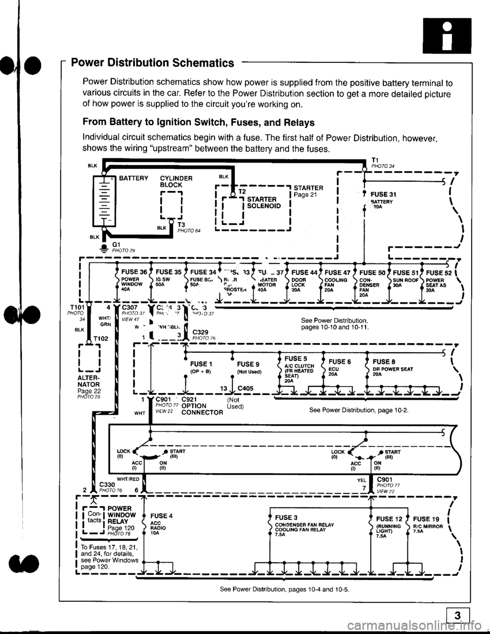
Power Distribution schematics show how power is supplied from the positive battery terminal to
various circuits in the car. Refer to the Power Distribution section to get a more detailed picture
of how power is supplied to the circuit you're working on.
From Battery to lgnition Switch, Fuses, and Relays
Individual circuit schematics begin with a fuse. The first half of Power Distribution, however,
shows the wiring "upstream" between the battery and the fuses.
CYLINDERBLOCK
tl
tlL.lt J
",-* f ]fo,o
i BATTERY
IIII
-
----------------Y-?-
ruse so I ruse as I ruse ga | ' ,s. ,a I =u. - srl ruse aai ruse qr I ruse so I ruse sr i ruse iapowEF csw FUsE Bc, \F,.n .;,cren ooon \coounc cor,r. \sun noor powrnw'NDowf50a {* .i1-;.*"1liT""fi3f* f5# fffi'*"f'* fS?'*
- - -L - - -. ... Ji - -.J.- - - -e- - -l. - - -La - J- - - I - - -
"";%,, Y rtr,' .9 l' -%,t",,vtEw47 I ! See Power Dastribution,w - vH-,alr. lt - pages 10,10and 10-11.
' I ---il 9,1?-l--4F--?-
i I
t.urr, 'rrr.,
t i!?'.,,?"" t::=. l ty::.1----.-
-
i
a I r(op-B) .{Noru3€d) J$ifl#ii Jtocl }3fo**."".o'
t -L - - -L - - -: rJ:e'- - -Ei s+s-r -.Fl-J-Jrr.-.
It-STARTER | !Pase 21 ! t FUSE 31I "rn*i
I f
*
i.Jr;-t
i L_i***'" iL-------J
ilr------!
FUSE /I4 ' FUSE 47 ' FUSE 5{' ' FUSE 51' FUSE 52
rlr
OOOB \COOLING CON. \SUN BOOF FOWER
t3f* f5# fffi*" f'* fs?'*
See Power Dastribution,pages 10'10 and 10-11.
T101
34
ALK
4
GAN
I
I
I
I
I\
\I
I
I
FUSE 8DF POWEF SEAT204
FUSE 6ECU204
FUSE 5A/C CLUICH(FN HEATEDSEAD204
C901 C921 {NotPHoro zz OPTION Used)v/EW22 CONNECTOBSee Power Distnbution, page 10-2.
1
FUSE 4
FADIO104
c901
vlEw22
FUSE 12(BUltNrrGLIGHT)
FUSE 19R/C MIRROF
YEL
7
i-f,r-- 't PowERI uon- I Wlt{DOWi racrs i RELAY. t P^da 1tL-J P;dr1ii-
FUSE 3CONOENSEF FAN RELAYCOOLING FAN RELAY
To Fuses 17, 18, 21,and 24, for details,see Power Windowspage 120.a
ll
ll
ALTER-NATORPage 22
f102
c330
See Power Distribution, pages 10-4 and 10-5.