Page 1227 of 2189
Troubleshooting
Central Processing Unit (CPUI
Diagnostic Troublo Code IDTC) 81: CPU Disgnosis
- With the ignition switch ON{lll. ABS indicator light doesnot go oft.- With tho SCS servi@ connec-tor conn€cted lsee page 19{6},DTC 81 is indicated.
P.oblem vedfication:1. Erase the DTC.2. Test-drive the vehicle.3. Make sure that the ABS indi,cator light comes on and DTC81 is indicated.
ls DTC 81 indicated?R€pllc6 th. ABS control unh.
The system k OK rt this time.
19-74
Page 1394 of 2189
Troubleshooting -'99 - 00 Models
Self-diagnosis Function
The heater control panel has a self-diagnosis function.
Running the Self-diagnosis Funqtion
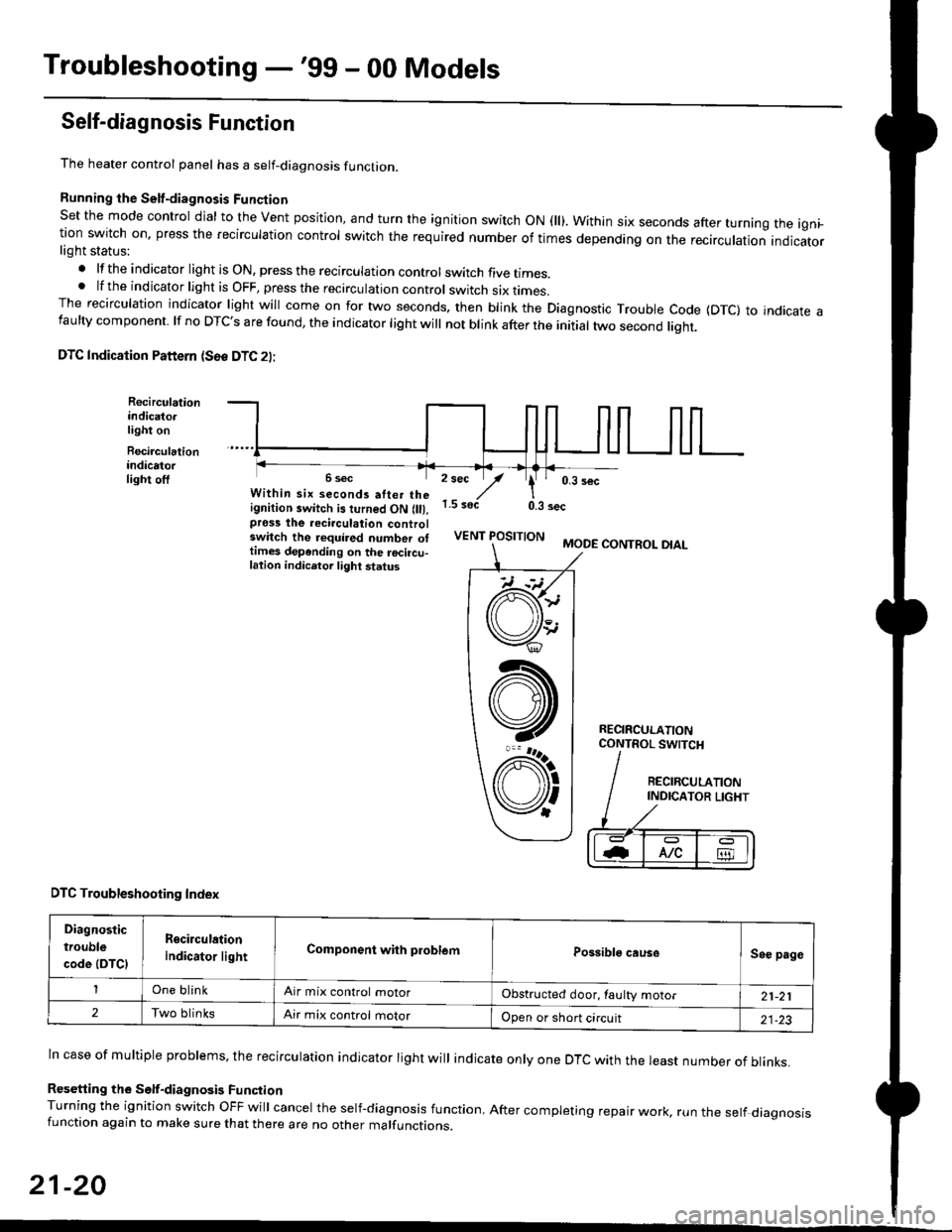
Set the mode control dial to the Vent position, and turn the ignition switch ON fll). Within six seconds after turnang the igni_tion switch on. press the recirculation control switch the required number of times depending on the recirculation indicatorlight status:
.lftheindicatorlightisON,presstherecirculationcontrolswitchfivetrmes.
.lftheindicatorlightisOFF,presstherecirculationcontrol switch six rrmes.The recirculation indicator light will come on for two seconds. then blink the Diagnostic Trouble code {DTc} to indicate afaulty component. lf no DTc's are found, the indicator light will not blink after the initial two second liqht.
DTC Indication Pattern (S6e DTC 2l:
Recirculationindicato.light on
Recirculationindicatorlight off2 sec
,/1.5 soct
' 0,3 secWithin six seconds atter theignition switch is turned ON (lll,pross the recirculation controlswitch the required number ottimes depending on the rocircu-lation indicetor light status
0.3 sec
VENT POSITIONMODE CONTROL DIAL
RECIRCULATIONCONTROL SWTCH
DTC Troubleshooting Index
Diagnostic
trouble
code (DTCI
Rgcirculation
indicator lightComponent with problemPossible causeSee page
One blinkAir mix control motorObstructed door, laulty motor21-21
2Two blinksAir mix control motorOpen or short circuit21-23
ln case of multiple problems, the recirculation indicator light will indicate only one DTc with the least number of blinks.
Resetting the Self-diagnosis FunctionTurning the ignition switch OFF will cancel the self-diagnosis function, After completing repair work, run the setf diagnosisfunction again to make sure that there are no other malfunctions.
21-20
@
At
V'
Page 1395 of 2189
Air Mix Gontrol Motor
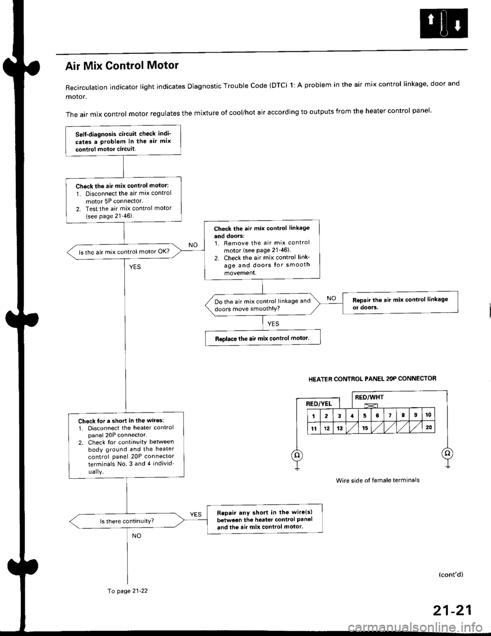
Recirculation indicator light indicates Diagnostic Trouble code (DTC) 1l A problem in the air mix control linkage, door and
motor.
The air mix control motor regulates the mixture of cool/hot air according to outputs from the heater control panel'
Self-diagnosis circuit check indi'
cates a Problem in the air mix
conlrol motor circuit,
Check th6 aii mix conirol motor:
1. Disconnect the air mix control
motor 5P connector.
2. Test the air mix control motor(see page 21-46).
check the air mix control linkage
and doors:1. Remove the air mix control
motor (see Page 21-46)
2. Check the air mix control link-
age and doors lor smooth
movement.
ls the air mix control motor OK?
Do the air mix control linkage and
doors move smoolhlY?
R€olace the air mix control motor'
Check tor a short in the wiles:
1. Disconnect the heater controlpanel 20P connector-2. Check for continuitY between
body ground and the heater
control panel 20P connector
terminals No.3 and 4 individ'
uaIY.
Ropair any short in th€ wire{s}
betweon the heater control Paneland the air mix control motor'
HEATER CONTROL PANEL 2OP CONNECTOR
RED/WHTRED/YEL
Wire side ot female terminals
(cont'd)
fo page 21-22
21-21
Page 1397 of 2189
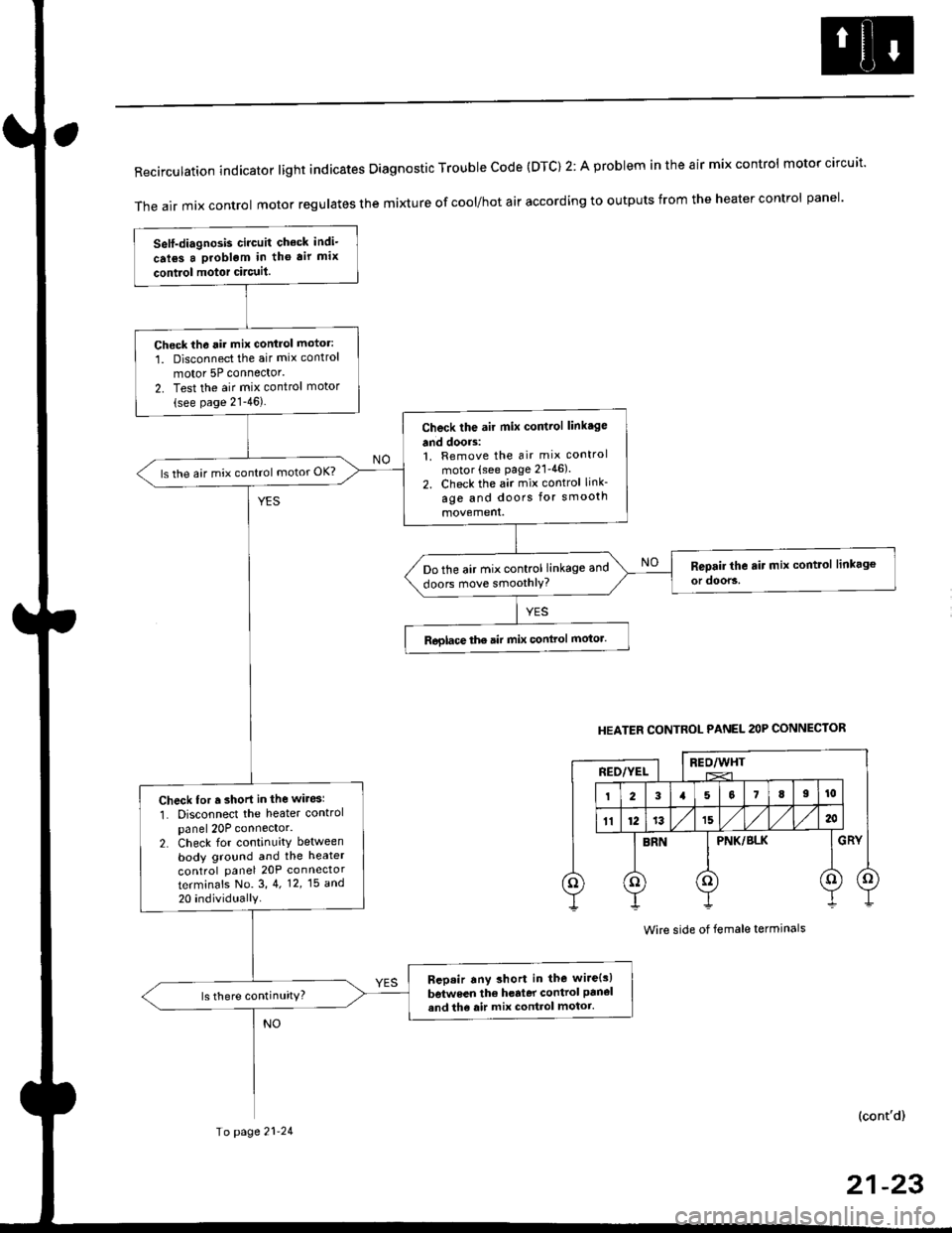
RecirculationindicatorIightindicatesDiagnosticTroublecode(DTc)2:AprobIemintheairmixcontro|motorcircuit.
The air mix control motor regutates the mi)dure of cool/hot air according to outputs from the heater control panel'
Self-diagnosis circuit check indi-
crl6s a problgm in tho air mix
contiol motor circuit.
Check th6 rir mix control motor:
1. Disconnect the air mix control
motor 5P connector'
2. Test the air mix control motor(see page 21-46).
Check the air mix control linkage
and doors:1. Remove the air mix control
motor (see page 21'46).
2. Check the air mix control link-
age and doors for smooth
ls the air mix control motor OK?
Do the air mix control linkage and
doors move smoothlY?
Roglace the air mix conlrol motor.
Check for r short in the wiresl
1. Disconnect the heater controlpanel 20P connector.2. Check for continuity between
body ground and the heater
control panel 20P connector
terminafs No. 3,4. 12,15 a^d
20 individually
Bep.ir any short in the wire{s)
between the h€rter control panel
and th6 air mix control motor.ls there continuity?
HEATER CONTROL PANEL 2OP CONNECTOR
BEO/WHTREO/YEL
PNK/BLK
Wire side of female terminals
(cont'd)
Io page 21-24
21-23
Page 1739 of 2189
)
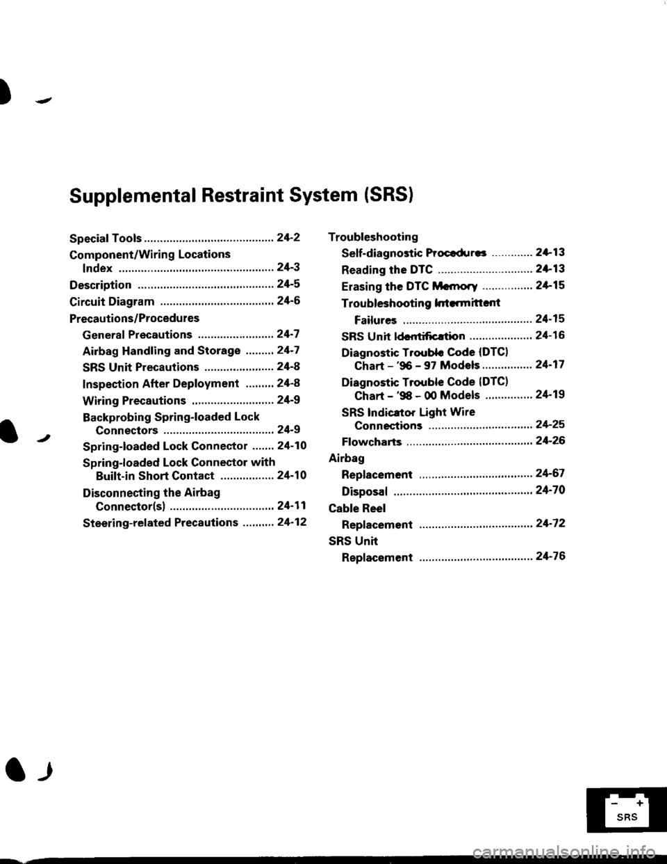
Troubleshooting
Sef f -dia gnostic Proctdurcs ............. 2+13
Reading the DTC .............................. 2+13
Erasing the DTC Mcnrory ................ 24-15
Troubleshooting h.ttnitt.nt
Failures ..............24-15
SRS U n it ldcntificrtion .................... 24- 1 6
Diagnostic Troublc Code (DTC)
Chart - '96 - 97 Models..."'."....... 24-17
Diagnostic Trouble Code (DTCI
Chart - '$ - 00 Models '.........""' 24'19
SRS lndicaror Light Wire
connections ...'.,24-25
Ff owcharts ........,,,,.24-26
Airbag
Repfacemant ...'.'...24-67
Disposaf .................24'70
Cable Reel
Repfacement .........24'72
SRS Unh
Repfacement ..'......24'76
l-l
-+
sRs
Supplemental Restraint System (SRSI
Speciaf Tools ... ...........24'2
Component/Wirin g Locations
fndex ................ ......24-3
Description ................ 24-5
Circuit Diagram ......." 24'6
Precautions/Procedures
Generaf Precautions ...............,,,,,,,.. 24-7
Airbag Handling and Storage .........24-7
SRS Unit Precautions ...................... 24-8
Inspection After Deployment ........' 24-8
Wiring Precautions ................... ....... 24'9
Backprobing Spring-loaded Lock
Connectors .......,24-9
Spring-loaded Lock Connectol ....,,. 24-10
Spring-loaded Lock Connector with
Built-in Short Contact ................. 24-10
Disconnecting the Airbag
Connector(sl .....' 24'11
Steering-related Precautions ...,.,.,,. 24'12
Page 1751 of 2189
rl
Troubleshooting
t)
Self-diagnostic Procedures
The self-diagnostic function of the SRS system allows it to locate the causes of system problems and to store this informa' I
tion in memory. For easier troubleshooting, this data can be retrieved via a data link circuit l
. When you turn the ignition switch ON (ll), the SRS indicator will come on. ll it goes off after six seconds. the system is
norma l.
. lf there is an abnormality, the system locates and defines the problem, stores this information in memory, and turns
the sRS indicator light on. The data will remain in the memory even when the ignition switch is turned off or if the bat-
tery is disconnected.
o when you connect the scs service connector to the service check connector (2P), and turn the ignition switch oN (ll),
thesRsindicator|ightwi||indicatethediagnostictroub|ecode(DTC)bythenumberofb|inks.
. After reading and recording the DTC. proceed with the troubleshooting for this code'
Precauiions
.Useon|yadigita|mU|timetertocheckthesystem'|fit,snotaHondamu|timeter,makesureitsoutputisl0mA(0.01A)
or|esswhenSwitchedtothesma||estva|ueintheohmmeterrange,AtesterwithahigheroUtpUtcoulddamagethe��
airbag circuit or cause accidental airbag deployment and possible injury'
r when-ever the ignition switch is oN (ll). or has been turned oFF for lessthan three minutes, be careful nottobumpthe
SRS unit; the airbags could accidentally deploy and cause damage or injuries
. Before you ,"n1ou" th" SRS main harness, disconnect the driver's airbag connector (and the front passenger's airbag
connector).
. Make sure the battery is sufficiently charged {see section 23}. lf the battery is dead or low, measuring valLles won t be
correct.
. Do not touch a tester probe to the terminals in the sRS unit or harness connectors, and do not connect the terminals
with a jumper wire. Use only the backprobe set or the special tools'
For backprobing spring-loaded lock type connectors, refer to page 24-9'
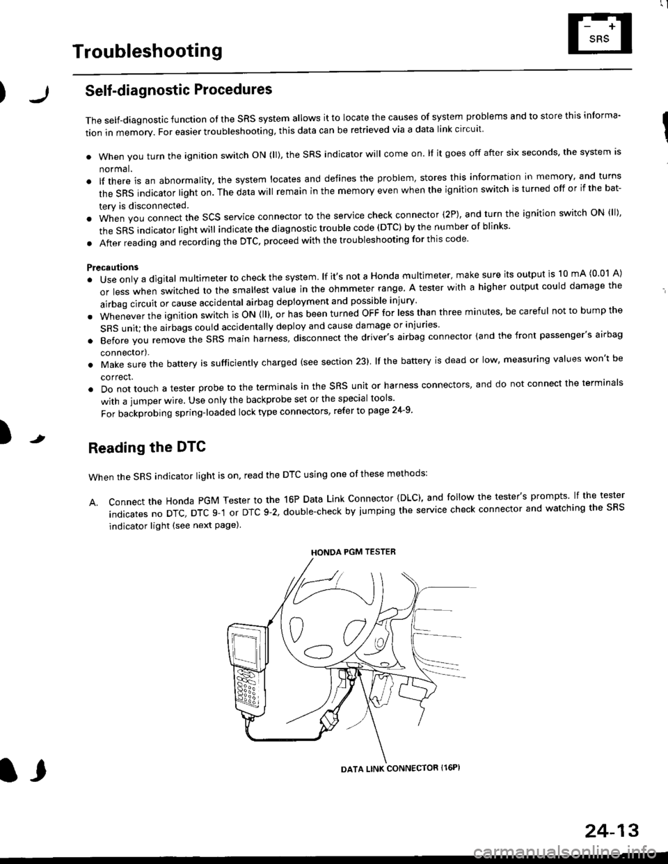
Reading the DTC
when the SRS indicator light is on, read the DTC using one of these methods:
A. Connect the Honda PGM Tester to the 16P Data Link Connector {DLC), and follow the tester's prompts lf the tester
indicatesnoDTc,DTcg-1orDTc9-2,doub|e-checkbyjumpingtheservicecheckconnectorandwatchingthesRS
indicator light (see next Page)
HONDA PGM TESTER
DATA LINK CONNECTOR Il6PI
l,
24-13
Page 1755 of 2189
l
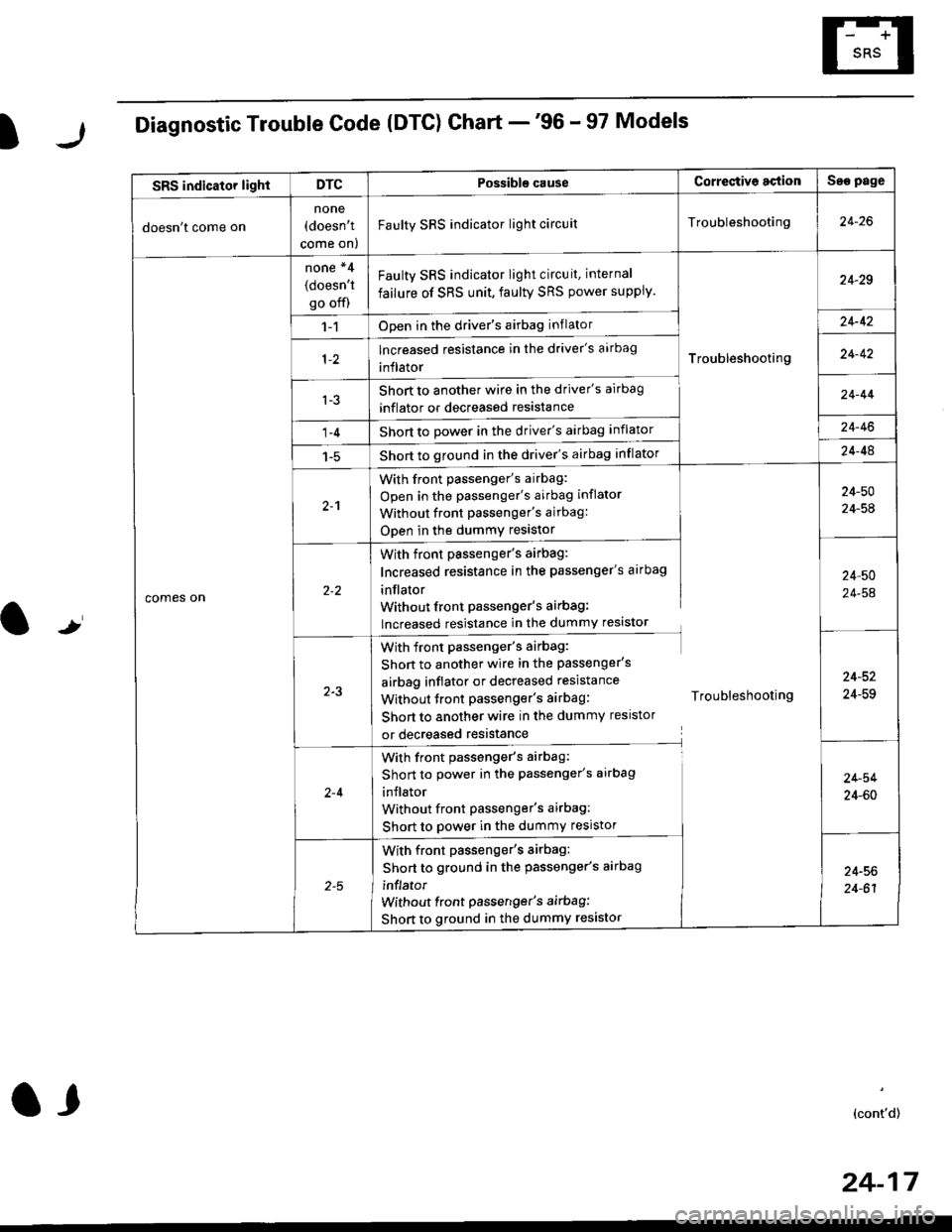
Diagnostic Trouble Code (DTG) Chart -'96 - 97 Models
t
SRS indicator lightDTCPossible causeCorrectiv6 actionSae page
doesn't come on
none(doesn't
come on)
Faulty SRS indicator light circuitTroubleshooting24-26
comes on
none *4
(doesn't
go off)
Faulty SRS indicator light circuit, internal
failure of SRS unit, faulty SRS power supply.
Troubleshooting
24-29
1-1Open in the driver's airbag inflator24-42
lncreased resistance in the driver's aarbag
inflator24-42
l-3Short to another wire in the driver's airbag
inflator or decreased resistance
Short to Dower in the driver's airbag inflator
Short to ground in the driver's airbag inflator
24-44
1-424-46
1-524-48
2-1
With front passenger's airbag:
Open in the passenger's airbag inflator
Without front Passenger's airbag:
ODen in the dummy resistor
24-50
24-54
With front passenger's airbag:
Increased resistance in the passenger's airbag
inflator
Without front Passenger's airbag:
lncreased resistance in the dummy resistor
24,50
24-54
2-3
With front passenger's airbag:
Shon to another wire in the passenger's
airbag inflator or decreased resistance
Without tront passenger's airbag: Troubleshooting
Short to another wire in the dummy resistor
or decreased resistance
24-52
24-59
2-4
With front passenger's airbag:
Short to power in the passenger's airbag
inJlator
Without front Passenger's airbag:
Short to power in the dummy resistor
24-54
24-60
With front passenger's airbag:
Short to ground in the passenger's aarbag
inflator
without front passenger's airbag:
Short to ground in the dummy resistor
24-56
24-61
(cont'd)
24-17
a,
Page 1756 of 2189
Troubleshooting
Diagnostic Trouble Code (DTCI Ghart -'96 - 97 Models (cont'd)
NOTE:* l: In case of an intermittent failure DTC g-1, it means there was an internal failure of the SRS unit or a faultv SRS indicator light circuit. Do the troubleshooting for intermittent failures (see page 24-15).*2: lt both DTC 9-2 and DTC 5-1 are indicated, do the troubleshooting for DTC g-2.*3: Apply to the '97 model coupe HX and DX.*4: DTC cannot be read with a Honda PGM Tester; check by jumping the SCS service connector.
24-18
.
Possiblg cause Cortestive action
5 3 I Internal failure of the SRS unitSRS unit
replacement
lnternal failure of the SRS unitSRS unit
replacement
Internal failure of the SRS unit
Internal failure of the SRS unitSRS unit
replacement
Internalfailure of the SRS unit ortwo failures at atime
8-6*3 Internalfailure ofthe SRS unit
Internal failure of the SRS unit
Faulty SRS power supply (VB line)
SRS unit replacement code (SRS unit must not
be used any longe.)
J