Page 1757 of 2189
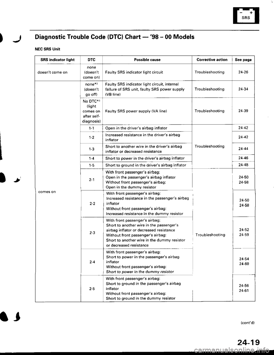
)Diagnostic Trouble Code (DTC) Chart -'98 - 00 Models
NEC SRS Unit
Ir
SRS indicator lightDTCPossible causeCorrestive actionSee page
doesn't come on
none
(doesn't
come on)
Faulty SRS indicator light circuitTroubleshooting24-26
comes on
none*3
(doesn't
go off)
Faulty SRS indicator light circuit, internal
fallure of SRS unit, faulty SRS power supply
(VB line)
Troubleshooting24-34
No DTC*3(lis ht
comes on
after self-
diagnosis)
Faulty SRS power supply (VA linelTroubleshooting24-39
l-1Open in the driver's airbag inflator
Troubleshooting
24 42
Increased resistance in the driver's airbag
inflator24-42
Short to another wire in the driver's airbag
inflator or decreased resistance24-44
't -4Short to power in the driver's airbag inflator24-46
t-5Short to ground in the driver's airbag inflator24-48
With front passenger's airbag:
Open in the passenger's airbag inflator
Without front passenger's airbag:
Open in the dummv resistor
24-50
24-54
With front passenger's airbag:
Increased resistance in the passenger's airbag
inflator
Without front passenger's airbag:
Increased resistance in the dummy resistor
24-50
24-58
with front passenger's airbag:
Short to another wire in the passenger's
airbag inflator or decreased resistance
Without front passenger's airbag:
Short to another wire in the dummy resistor
or decreased resistance
Troubleshooting
24-52
24,59
2-4
With front passenger's airbag:
Short to power in the passenger's airbag
inflator
Without front passenger's airbag:
Shon to power in the dummy resistor
24-54
24-60
With front passenger's airbag:
Short to ground in the passenger's airbag
inflator
Without front passenger's airbag:
Short to ground in the dummy resistor
24-56
24-61
(cont'd)
24-19
l,
Page 1758 of 2189
Troubleshooting
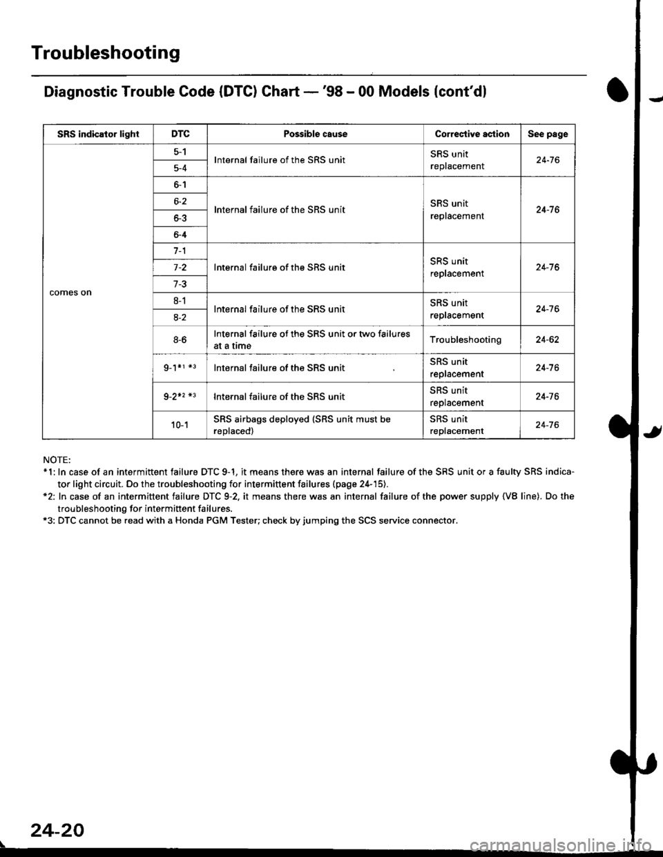
Diagnostic Trouble Code (DTC) Chart -'98 - 00 Models {cont'dl
NOTE:* 1: In case of an intermittent failure DTC 9-1, it means there was an internal failure of the SRS unit or a faulty SRS indica-
tor light circuit. Do the troubleshooting for intermittent failures (page 24-'15).*2: In case of an intermittent failure DTC 9-2, it means there was an internal failure of the power supply {VB line). Do the
troubleshooting for intermiftent failures.*3: DTC cannot be read with a Honda PGM Tester; check by jumping the SCS service connector.
24-20
\
SRS indicator lightDTCPossible causeCorrectiYe actionSee page
comes on
5-1lnternal failure of the SRS unitSRS unit
replacemenl24-765-4
6-1
lnternal failure of the SRS unitSRS unit
replacement24-7 66-2
o-5
6-4
7-1
lnternal failure of the SRS unitSRS unit
replacement24-76
7-3
8-1lnternal failure of the SRS unitSRS unit
reptacement24-7 68-2
8-6Internal failure of the SRS unit or two failures
at a trmeTroubleshooting24-62
g_1*r *3lnternal failure of the SRS unitSRS unit
replacement24-7 6
9-2+2 *3lnternal failure of the SRS unit5l|5 Untr
replacement24-76
10-1SRS airbags deployed (SRS unit must be
reDlaced)
SRS unit
replacement24-76
Page 1760 of 2189
Troubleshooting
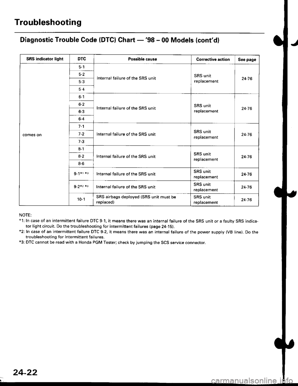
Diagnostic Trouble Code (DTCI Ghart -'98 - 00 Models (cont'd)
NOTE:*l: In case of an intermittent failure DTC 9-1. it means there was an internal failure of the SRS unit or a faultv SRS indica-
tor light circuit. Do the troubleshooting for intermiftent failures (pa9e 24-15).*2: In case of an intermittent failure DTC 9-2, it means there was an internal failure of the power supply (VB line). Do thetroubleshooting for intermittent failures.*3: DTC cannot be read with a Honda PGM Tester; check by jumping the SCS service connector.
SRS indicator lightDTCPossible causeCorective actionSeo page
comes on
5-2
53
54
lnternal failure of the SRS unitSRS unit
replacement24-7 6
6-1
6-2
_
64
Internal failure of the SRS unitSRS unit
replacement24-16
n
-
8l
8S
9_1*r *3
Internal failure of the SRS unitSRS unit
reptacement24-76
Internal failure of the SRS unitSRS unit
replacement24-76
Internal failure of the SRS unitSRS unit
replacement24-76
Internal failure of the SBS unitSRS unit
reptacemenr24-76
10-1SRS airbags deployed (SRS unit must be
reDlaced)
SRS unit
replacement24-76
24-22
Page 1762 of 2189
Troubleshooting
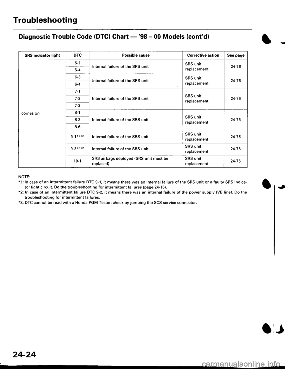
Diagnostic Trouble Code (DTG) Chart -'98 - 00 Models (cont'dl
NOTE:*'l: In case of an intermittent failure DTC 9-1. it means there was an internal failure of the SRS unit or a faulty SRS indica-
tor light circuit. Do the troubleshooting for intermiftent failu.es (page 24-15).*2: In case ot an intermittent failure DTC 9-2. it means there was an internal failure of the power supply (VB line). Do the
troubleshooting for intermift ent failures.*3: DTC cannot be read with a Honda PGM Tester; check by jumping the SCS service connector.
24-24
a,
SRS indicator lightDTCPossible causeCorective actionSee page
comes on
lnternal failure of the SRS unitSRS unit
repracemenl24-765-4
6-3lnternal failure of the SRS unitSRS unit
reptacemenr24-766-4
Internal failure of the SRS unitSRS unit
replacement24-7 6
8-1
lnternal failure ot the SRS unitSRS unit
replacement24-7 68-2
8-6
g_1*r *rInternal failure of the SRS unitSRS unit
replacement24-16
lnternal failure of the SRS unitSRS unit
repracemenl24-76
10-1SRS airbags deployed (SRS unit must be
.eplaced)
SRS unit
reptacemenl24-76
Page 1983 of 2189
A/T Gear Position Indicator (conrd)
- How the Circuit Works
With the ignition switch in ON (ll) or START (lll),
voltage is applied to the A,/T gear position indicator.
The A,/T gear position switch provides a ground for
each position. As an input is grounded, its indicator
light comes on. lf you select R, for example, ground
will be provided to the input of the A,/T gear position
indicato( and the R indicator will come on.
With the headlight switch in PARK or HEAD, voltage
is applied to the RED/BLK wire terminal. This
changes the indicator panel illumination from fixed
to controlled by the dash lights dimmer input
through the RED wire.
When the powertrain (all except '96-'98 CVT) or
transmission ('96198 CVT) control module (PCM or
TCM) detects an abnormality in the automatic
transmission control system, or when you request
diagnostic trouble codes through the service check
connector, the PCM or TCM will make the D4 (D for
CVT) indicator light blink.
Refer to the Service Manual (Section 14,
Automatic Transmission) for specific tests or
troubleshooting procedures.
\ia
89-2