1998 HONDA CIVIC crank
[x] Cancel search: crankPage 862 of 2189

Transmission
Installation (cont'dl
9. Attach the torque converter to the drive plate witheight drive plate bolts and torque as follows:Rotate the crankshaft pulley as necessary to tightenthe bolts to 1/2 of the specified torque. then to thefinal torque, in a crisscross pattern.
After tightening the last bolt, check that the crank-shaft rotates freely.
TOROUE: 12 N.m {1.2 kgl.m, 8.7 tbt{r}
10 x 1.25 mm
6x1.0mm12 N.m (1.2 kgt m,8.7 rbt ft)
I 1.25 mm2/t N.m {2.4 kg{.m,17 tbt ftlCONVERTEB
10. Install the torque convener cover and the €nginestiffener.'11. Tighten the crsnkshaft pull€y bolt, if necessary (see
section 61.
12. Connect the ATF cooler hoses to the ATF cooler lines(see page 1,t192).
ATF COOIIRUNE
10 x 1.25 mma,l N.m {4.5 kgl.m,33 rbt.fttRIGHT FRONT 12 x 1.25 mmMOUNT/BRACKET 6.t N.m (6.5 kg{.m,47 tbt ftl
13. Install the right front mounvbracket.
4,r N.m 14.5 kgf.m,33 lbtft)
COVER
L,
14-1A4
SHIFT CABLE
SHIFT CAAE COVER
14. Install the control lever with a new lock washer tothe control shaft, then install the shift cable cover.
CAUION: Taks care not to bend the shift cable.
L(rcK WASHERReplace.
8 x 1,25 r'|m22N-m12.2 tgt m. 16lbnftl
x 1.0 mmtit N.m 11.4 kgt m,10 tbr,ft,
15. lnstall the exhaust pipe A.
NOTE: D16Y8 engine is shown; D16y/ engine is sim_ilar.
Replace.
GASKETReplace.
SELF.LOCKING NUTReplace.10 x 1.25 mm54 N.m (5.5 lgf.m,40 tbt ftl
NUTSELF.LOCKING NUTReplace.8 x 1.25 mm22 N.m {2.2 kgl.m, 16lbtfrl
Replace.8 x 1.25 mm16 N.m {1.6 kgI.m,12 tbf.ft)
Page 873 of 2189

Description
The Continuously Variable Transmission (CVT) is an electronically controlled automatic transmission with drive and driv
en Oullevs, and a steel belt. The CVT provides non stage speeds forward and one reverse. The entire unit is positioned in
line with the engine.
Transmission
Around the outside of the flywheel is a ring gear which meshes with the starter pinion when the engine is being staned.
The transmission has four parallel shafts: the input shaft, the drive pulley shaft. the driven pulley shaft, and the secondary
gear shaft. The input shaft is in line with the engine crankshaft. The drive pulley shaft and the driven pulley shaft consist of
movable and fixed face pulleys. Both pulleys are linked by the steel belt.
The input shaft includes the sun gear. The drive pulley shaft includes the forward clutch which mounts the carrier assem-
bly on the forward clutch drum. The carrier assembly includes the pinion gears which mesh with the sun gear and the ring
gear. The ring gear has a hub-mounted reverse brake disc.
The driven pulley shaft includes the start clutch and the secondary drive gear which is integral with the park gear' The sec-
ondary gear shaft is positioned between the secondary drive gear and the final driven gear. The secondary gear shaft
includes the secondary driven gear which serves to change the rotation direction. because the drive pulley shaft and the
driven oullev shaft rotate the same direction. When certain combinations of planetary gears in the transmission are
engaged by the clutches and the reverse brake, power is transmitted from the drive pulley shaft to the driven pulley shaft
to provide E, E, E, and El.
Electronic Control'96 - 98 Models:
The electronic control system consists of the Transmission Control Module (TCM), sensors, three linear solenoids, and a
inhibitor solenoid. Shifting is electronically controlled under all conditions'
The TCM is located below the dashboard, behind the kick panel on the driver's side.'99 - 00 Models:
The electronic control svstem consists of a Powertrain Control Module (PCM), sensors, three linear solenoids and an
inhibitor solenoid. Shifting is electronically controlled under all conditions. A Grade Logic Control System to control shift-
ing in E position while the vehicle is ascending or descending a slope.
The PCM is located below the dashboard, under the kick panel on the passenger's side.
Hydraulic Control
The lower valve body assembly includes the main valve body, the Pressure Low (PL) reguiator valve body, the shift valve
body, the start clutch control valve body, and the secondary valve body. They are positioned on the lower part of the
transmission housing.
The main valve body contains the Pressure High (PH) control valve, the lubrication valve, and the pitot regulator valve.
The secondary valve body contains the PH regulator valve, the clutch reducing valve, the start clutch valve accumulator,
and the shift inhibitor valve. The PL regulator valve body contains the PL regulator valve and the PH-PL control valve
which is ioined to the PH,PL control linear solenoid. The inhibitor solenoid valve is bolted on the PL regulator valve body.
The shift valve body contains the shift valve and the shift control valve. which is joined to the shift control linear solenoid.
The start clutch control valve body contains the start clutch control valve, which is joined to the start clutch control linear
solenoid. The linear solenoids and the inhibitor solenoid are controlled by the TCM or PCM. The manual valve body which
contains the manual valve and the reverse inhibitor valve, is bolted on the intermediate housing.
The ATF pump assembly is located on the transmission housing, and is linked with the input shaft by the sprockets and
the sprocket chain. The pulleys and the clutch receive fluid from their respective feed pipes, and the reverse brake receives
fluid from internal hydraulic circuit.
Shift Control Mechanism
Input from various sensors located throughout the vehicle determines which linear solenoid the TCM or PCM will activate.
Activating the shift control linear solenoid changes the shift control valve pressure, causing the shift valve to move. This
pressurizes the drive pulley pressure to the drive pulley and the driven pulley pressure to the driven pulley and changes
their effective pulley ratio. Activating the start clutch control linear solenoid moves the start clutch control valve. The start
clutch control valve uncovers the port, providing pressure to the start clutch to engage it(cont'd)
14-195
,!
Page 983 of 2189

Transmission
Removal (cont'd)
10. Remove the cotte. pins and castle nuts, then separatethe ball joints from the lower arm (see section 1g).
SELF-LOCKING -=V,
NUT \Replace. oitupea rOax
Remove the right damper fork bolt, then separateright damper fork and damper.
Pry the right and left driveshafts out of the differen-tial.
Pull on the inboard joint to remove the right and leftdriveshafts (see section 16).
Tie plastic bags over the driveshaft ends.
NOTE: Coat all precision finished surfaces with cleanengine oil.
Remove the exhaust pipe A.
/\<,\CASTLE I{UT COTTERReplac6.
't 1.
't2.
tJ.
14.
q.
SELF.LOCKINGNUTReplace.
SELF.LOCKING NUTReplace.
14-306
EXHAUST PIPE A
19.
'16, Remove the right front mounvbracket,
ATF COOLER HOSE
17. Remove the ATF cooler hoses at the ATF coolerlines. Turn the ends of the ATF cooler hoses uo toprevent CVT fluid from flowing out, then plug theATF cooler hoses and lines,
NOTE: Check for any sign of leakage at the hosejoints.
18. Remove the engine stiffeners and the flywheel cover.
Remove the eight drive plate bolts one at time whilerotating the crankshaft pullev.
ENGINE STIFFENER
Page 1025 of 2189
l.
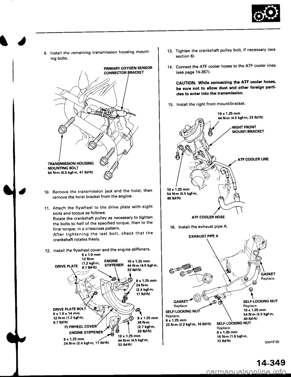
9. Install the remaining transmission housing mount-
ing bolts.
PRIMARY OXYGEN SENSOR
Remove the transmission jack and the hoist. then
remove the hoist bracket from the engine'
Attach the flvwheel to the drive plate with eight
bolts and torque as follows:
Rotate the crankshaft pulley as necessary to tighten
rhe bolts to half of the specified torque, then to the
final torque, in a crisscross pattern.
After tightening the last bolt. check that the
crankshaft rotates freelY.
10.
11.
12. Install the flywheel cover and the engine stiffeners
DRIVE
6xl.0mm12 N.m
- l12 kgf'm'rE 8.7 tbf.ftl
ENGINESTIFfENEB10 x 1.25 mmart N.m la.s kgt.m,33 tbtftt
8 x 1.25 mm24 N.m(2.1 kgf'm,17 tbt.ftt
DRIVE PI.ATE BOLT
6x1.0x14mm12 N.m {1.2 kgt m.
8.7 lbf,ftl8 x 1.25 mm26 N.m
12.7 kqfin,20 rbt'ftlFLYUTHEEL
ENGINE STIFFENER
8 x 1.25 mm10 x 1.25 mmr,a N.m {4,5 kgf m,
33 tbf.ftl
TRANSMISSION HOUSING
MOUNNNG BOLT
6il N.m {6.5 kgf.m, 47 lbf'ftl
24 N.m (2.4 kgt'm, '17 lbf'ftl
22 N.m t2.2 kgl m, 16lbf'ftl
14-349
13.
14.
Tighten the crankshaft pulley bolt, if necessary (see
section 6).
Connect the ATF cooler hoses to the ATF cooler lines
(see page 14-357).
CAUTION: Whilo connecting the ATF cooltr hGes,
b€ sure not lo allow dust and other loreign parti-
cles to entg. into the transmission.
15. Installthe right front mounvbracket'
10 x 1.25 mm
a,r N.m {4.5 kgf'm,33 lbt ftl
RIGHT FRONTMOUNT/BRACKET
ATF COOLER LINE
10 x 1 .25 mm54 N.m {5.5 kgt'm,
4{) tbl.ftt
ATF COOI,TR HOSE
16. Installthe exhaust PiPe A.
EXHAUST PIPE A
GASKETReplace.
@
\SELF.LOCKING NUTReplace.10 x 1.25 mm5/a N.m {5.5 kgt m,irc lbf.ft)
(cont'dl
*s$o
oor*rr-@Replace.
SELF.LOCKINGReplace.8 x 1.25 mmSELF.LOCKING NUT
Replace.8 x 1.25 mm16 N.m {1.6 kgl'm,12 tbl.ftt
Page 1072 of 2189
System Description
Fluid Flow Diagram
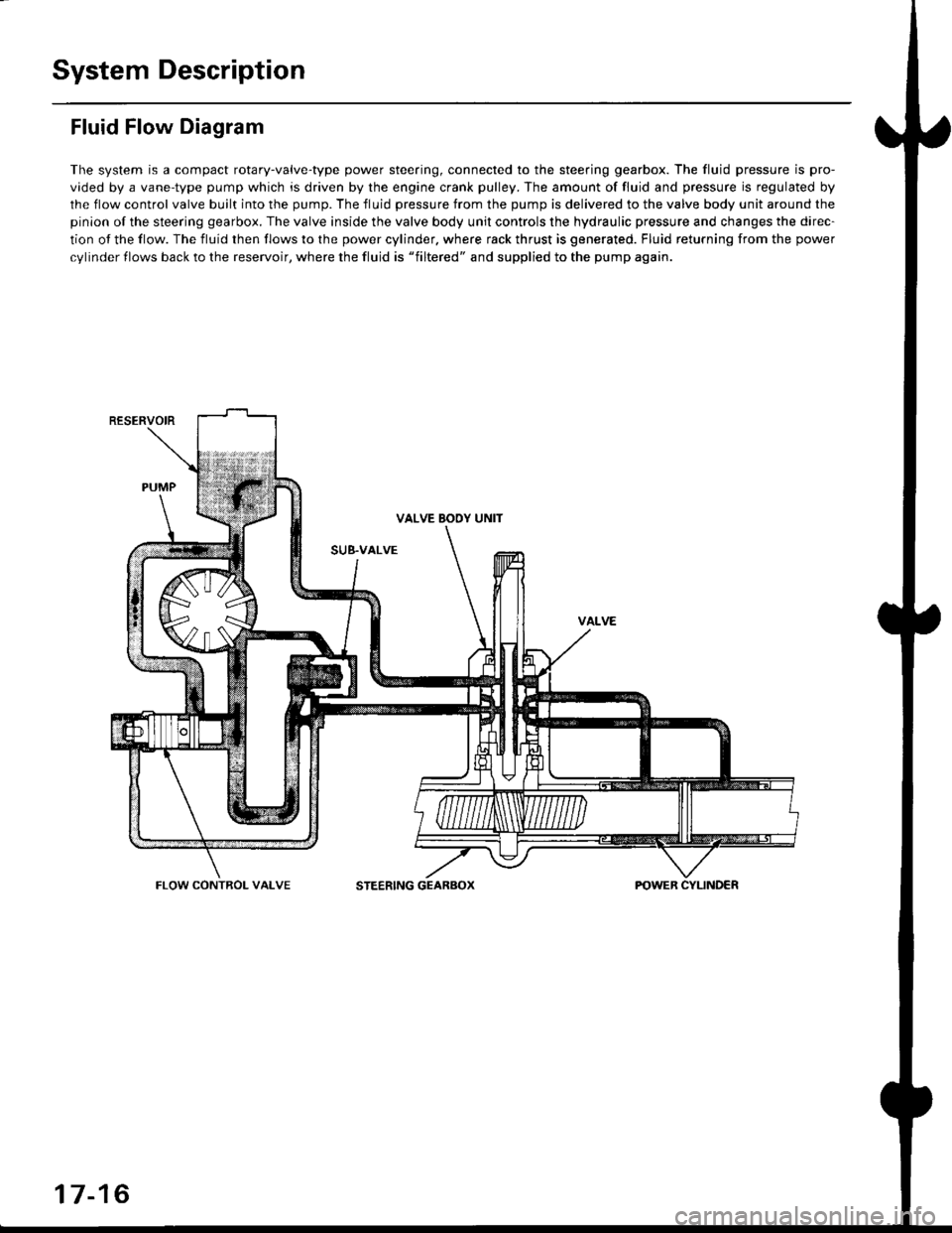
The system is a compact rotary-valve-type power steering, connected to the steering gearbox. The fluid pressure is pro-
vided by a vane-type pump which is driven by the engine crank pulley. The amount of fluid and pressure is regulated by
the flow control valve built into the pump. The fluid pressure from the pump is delivered to the valve body unit around the
pinion of the steering gearbox. The valve inside the valve body unit controls the hydraulic pressure and changes the direc-
tion of the flow. The fluid then flows to the power cylinder. where rack thrust is generated. Fluid returning from the power
cylinder flows back to the reservoir, where the fluid is "filtered" and supplied to the pump again.
RESERVOIR
VALVE BOOY UNIT
SUB.VALVE
FLOW CONTROL VALVESTEERING GEARBOX
17-16
Page 1073 of 2189
)
Steering Pump
Construction
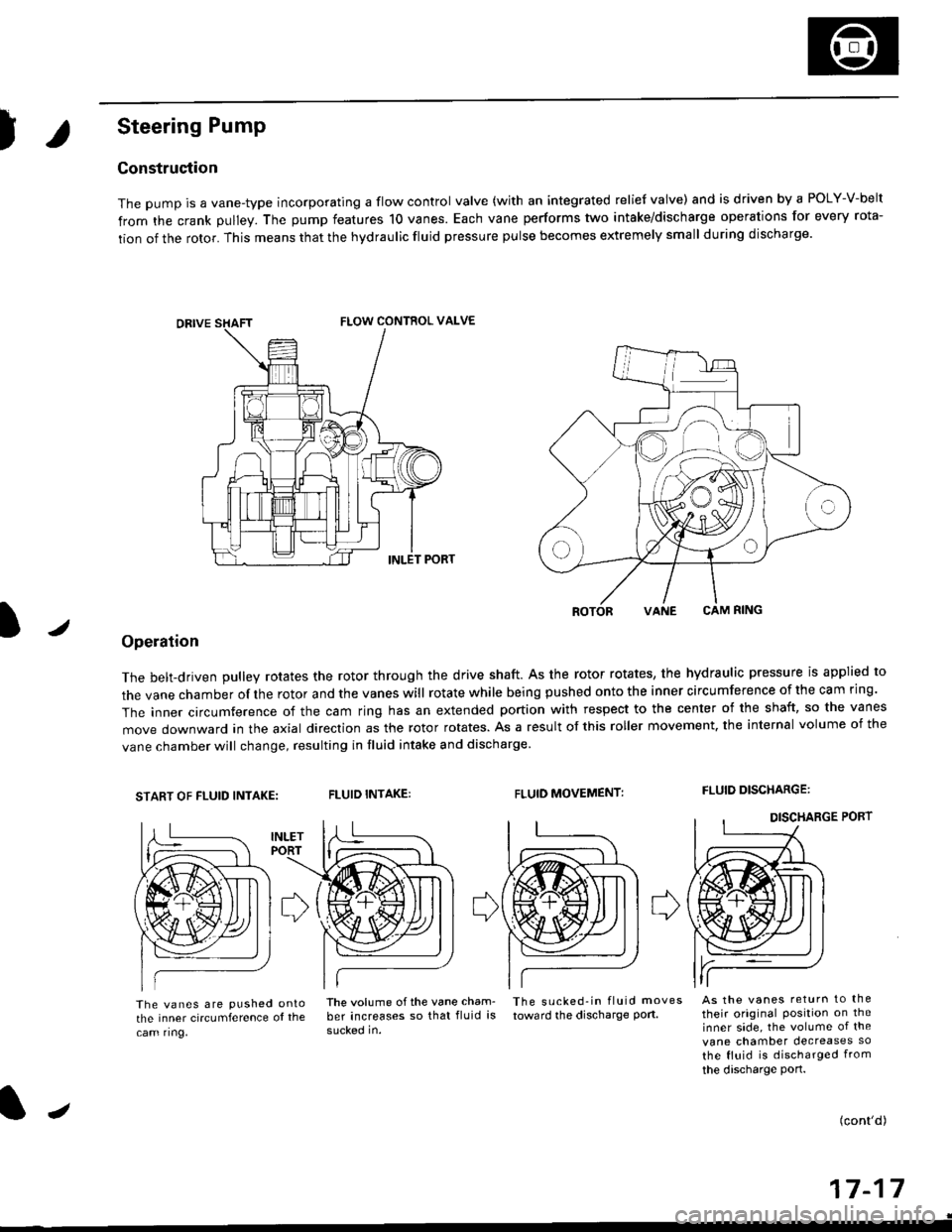
The pump is a vane-type incorporating a flow control valve (with an integrated relief valve) and is driven by a POLY-V-belt
from the crank pulley. The pump features 10 vanes. Each vane performs two intake/discharge operations for every rota-
tion of the rotor. This means that the hydraulic fluid pressure pulse becomes extremely small during discharge.
/
ROTORVANE CAM RING
Operation
The belt-driven pulley rotates the rotor through the drive shaft. As the rotor rotates, the hydraulic pressure is applied to
the vane chamber of rhe rotor and the vanes will rotate while being pushed onto the inner circumference of the cam ring.
The inner circumference of the cam ring has an extended portion with respect to the center of the shaft, so the vanes
move downward in the axial direction as the rotor rotates. As a result of this roller movement. the internal volume of the
vane chamber will change, resulting in fluid intake and discharge
START OF FLUID INTAKE:FLUID INTAKE:FLUID MOVEMENT:FLUID DISCHARGE:
The vanes are pushed ontothe inner circumference ol the
cam ring,
lhe volume ofthe vane cham- The sucked-in fluid moves
ber increases so that fluid is toward the discharge port.
sucked in.
As the vanes return to the
their original Position on theinner side, the volume of the
vane chamber decreases so
the fluid is discharged from
the discharge port.
(cont'd)
a-t 4-I I- | t
FLOW CONTROL VALVE
J
Page 1088 of 2189
Inspection and Adjustment
Pump Belt
NOTE: When using a new belt, first adjust the deflection
or tension to the values for the new belt, then readjust
the deflection or tension to the values for the used beltafter running engine for five minutes.
Inspection
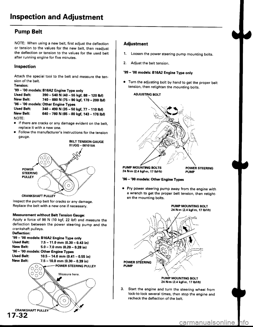
Attach the special tool to the belt and measure the ten-sion of the belt.
Tension:'99 -'00 mod€ls: B1642 Engin. Type onlyUsed Bsh: 390 - 540 N lao - 55 kgt.88 - 120 tbf)New Belt:740 - 880 N {75 - 90 kgf, 170 - 200 tbt}'96 - '00 models: Other Engine Types
Used Beh: 340 - 490 N (35 - 50 kgf, 77 - ilO tbflNew Belt:640 - 780 N 165 - 80 ksf, 1& - 176 tbf)NOTE:
. lf there are cracks or any damage evident on the belt,reDlace it with a new one.. Follow the manufacturer's instructions for the tensiongauge.
BELT TENSION GAUGE07JGG _ 001010A
Inspect the pump belt for cracks or any damage.Replace the belt with a new one if necessary.
Measuremont without Beh Tension Gauga:
Apply a force of 98 N (10 kgt,22 lbfl and measure thedeflection between the power steering pump and thecrankshaft pulleys.
Dsflectior:'99 -'00 model3: 816A2 Engine Typ€ ontyUsed Beh: 7.5 - 11.0 mm t0.30 - 0.43 inlNew Beh:5.0 - 7.0 mm (0.20 - 0.28 in)'96 - '00 models: Othor Engine Typos
Used Behi 10.5 - 14.0 mm (0.ial - 0.59 inlNow Beh:7.5 - 10.0 mm (0.30 - 0.39 inl
POWER STEERING PULUY
CRANKSHAFT PULLEY
17-32
Adiustment
1. Loosen the power steering pump mounting bolts.
2. Adjust the belt tension.
'99 - '00 mod€ls: 816A2 Engin€ Typo only
. Turn the adjusting bolt by hand to get the proper belttension, then retighten the mounting bolts,
ADJUSNNG BOLT
PUMP MOUNNNG BOLTS24 N.m (2.4 kgf'm, 17 tbtftlPOWER STEERINGPUMP
'96 -'00 modek: Othcr Engins Typos
. Pry power steering pump away from the engine witha wrench to get the proper belt tension, then retight-en the mounting bolts.
PUMP MOUNTING BOLT24 N.m (2,4 kgf.m, 17 lbl.ftl
PUMP MOUNTING BOLT24 N.m {2.a kgt m, 17 tbtftl
Start the engine and turn the steering wheel fromlock-to-lock several times, then stop the engine andrecheck the deflection of the belt,
Page 1242 of 2189
Doors
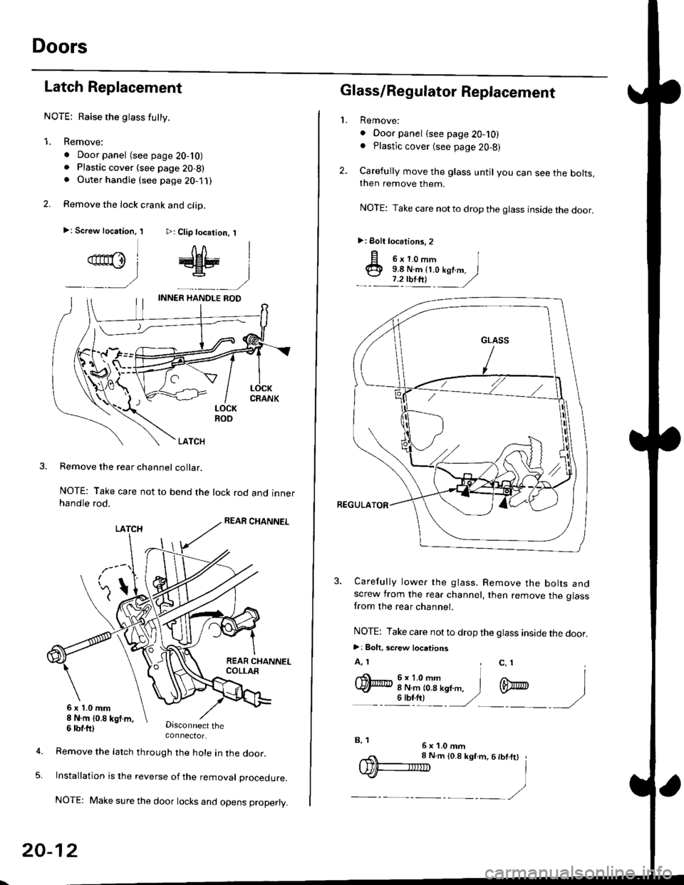
Latch Replacement
NOTE: Raise the glass futty.
1. Remove:
. Door panel (see page 20-10). Plastic cover (see page 20-8). Outer handle (see page 2O-1 ,l
2. Remove the lock crank and clip.
>: Screw location, I >: Clip location, I
qn@l # |
_ __) _-__)
LOCKROO
LATCH
Remove the rear channel collar.
NOTE: Take care not to bend the lock rod and innerhandle rod.
Disconnect theconnector.
6x1.0mm8 N.m (0.8 kgt m,
5.
6 tbtttl
Remove the latch through the hole in lne door.
lnstallation is the reverse of the removat proceoure.
NOTE: Make sure the door locks and opens properly.
20-12
,,< 8 N.m to.8 ksf.m, 6 tbt.ftt
IDF-IIID I
.)-__,/
2.
L
p o'r.o-,n I@ 9.8 N.m {t.o kof.m. I
.- :'zulnt -
/
3. Carefully lower the glass. Remove the bolts andscrew from the rear channel, then remove the glassfrom the rear channel.
NOTE: Take care not to drop the glass inside the door.
>: Bolt. screw locations
A, 1 , c, 1I
q)h:iT(--n,,". i m
- - illt) '/ -)
Glass/Regulator Replacement
Remove:
. Door panel {see page 20-10). Plastic cover (see page 20,8)
Carefully move the glass until you can see the bolts,then remove them.
NOTE: Take care notto drop the glass inside the door.
>: Eolt locations, 2
6x1.0mmB, 1