Page 1357 of 2189
Front Seat Belt
RemovaUlnstallation
2D l3Dl
1. Slide the front seat forward fully.
2. Remove:
. Rear seat-back and rear seat cushion (see pages
20-126,127l.
. Rear center shelf and rear side shelf (3D, see
page 20-60)
. Resr trim panel (3D, see page 2G60)
. Side trim panel (see pages 20-60, 61)
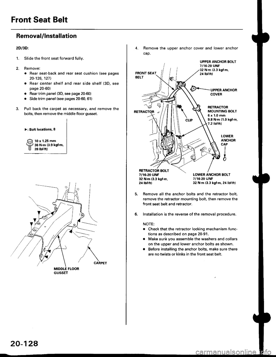
3. Pull back the carpet as necessary, and remove the
bolts, then remove the middle floor gusset.
>: Boh locations,8
10 x 1.25 mm38 N.m (3.9 kgf'm,28 rbtftl
20-124
4. Remove the upper anchor cover and lower anchor
cap.
UPPER ANCHOR EOLT7/16-20 UNF32 N.m {3.3 kgf.m,24 tbf.ftt
UPPER ANCHORCOVER
LOWERANCHOBCAPIIio
RETRACTORMOUNTING BOLT6x1.0mm9.8 N.m (1.0 kgf.m.7.2 tbl.hl
LOWER ANCHOR BOLT7/16-20 UNF32 N.m (3.3 kgt.m, 24 lbf.ft)
Remove all the anchor bolts and the retractor bolt.
remove the retractor mounting bolt, then remove the
Iront seat belt and retractor.
Installation is the reverse of the removal orocedure.
NOTE:
. Check that the retractor locking mechanism func-
tions as described on page 20-91
o Make suri vou assemble the washers and collars
on the upper and lower anchor bolts as shown.
. Before installing the anchor bolts, make sure there
are no twists or kinks in the front seat belt.
RETRACTOR AOLT7/16-20 UNF32 N.m 13.3 kgf.m,24 tbttrl
6.
Page 1370 of 2189
Body {'00 model}
Seat Belts
Child Seat Anchor Plate Removal/
f nstallation 20-142
Emblem
f nstallation 20-144
Outline of '00 Model Changes
The child seat anchor plate removal and installation procedures are different'
An emblem was added for some model of 3D.
Page 1371 of 2189
Seat Belts
Child Seat Anchor Plate Removal/lnstallation
2DllDl
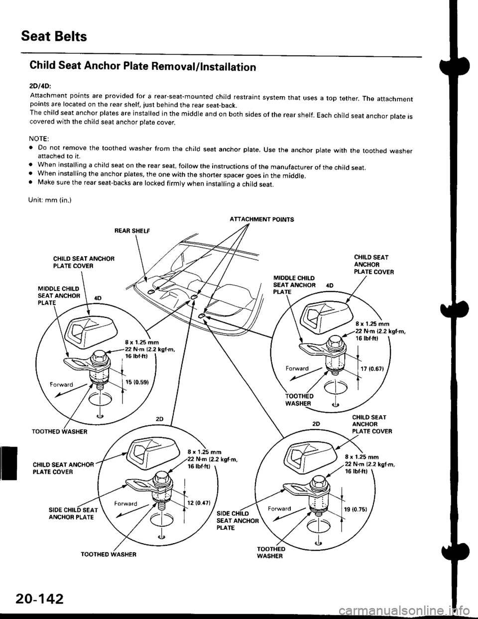
Attachment points are provided for a rear-seal-mounted child restraint system that usespoints are located on the rear shelf, tust behind the rear seat-back.The child seat anchor plates are installed in the middle and on both sides of the rear shelf.covered with the child seat anchor olate cover.
a top tether. The attachment
Each child seat anchor plate is
NOTE:
' Do not remove the toothed washer from the child seat anchor plate, Use the anchor plate with the toothed washerattached to it.
. When installing a child seat on the rear seat, follow the instructions of the manufacturer of the child seat.. When installing the anchor plates, the one with the shoner spacer goes in the middle.. Make sure the rear seat-backs are locked firmly when installing a child seat.
Unit: mm (in.)
REAR SHELF
CIIILD SEAT ANCHORPLATE COVER
MIDOLE CHILDSEAT ANCHOR
CHILO SEATANCHORPLATE COVER
CHILD SEATANCHORPLATE COVER
8 x 1.25 mm22 N.m 12.2 kgl m,
PLA
8 x 1.25 mm22 N.m 12.2 kgl.m,
I x 1.25 mm22 N.m 12.2 kgl.m,16 tbt.ftt
17 {0.67)
16 tbf.ft)
15 {0.s9)
WASHER
rl)
.t
TOOTHEO
ll ff*,".rd,',i"'"o*
SIDESEAT
I x 1,25 mmN.m {2.2 kgf.m.16 tbtftl
SIDE
16 tbf ftl
ANCHOR PLATESEAT ANCHORPLATE
ATTACHMENT POINTS
torward .
20-142
TOOTHED
12lO.47l19 (0.75)
Page 1425 of 2189
Air Conditioning
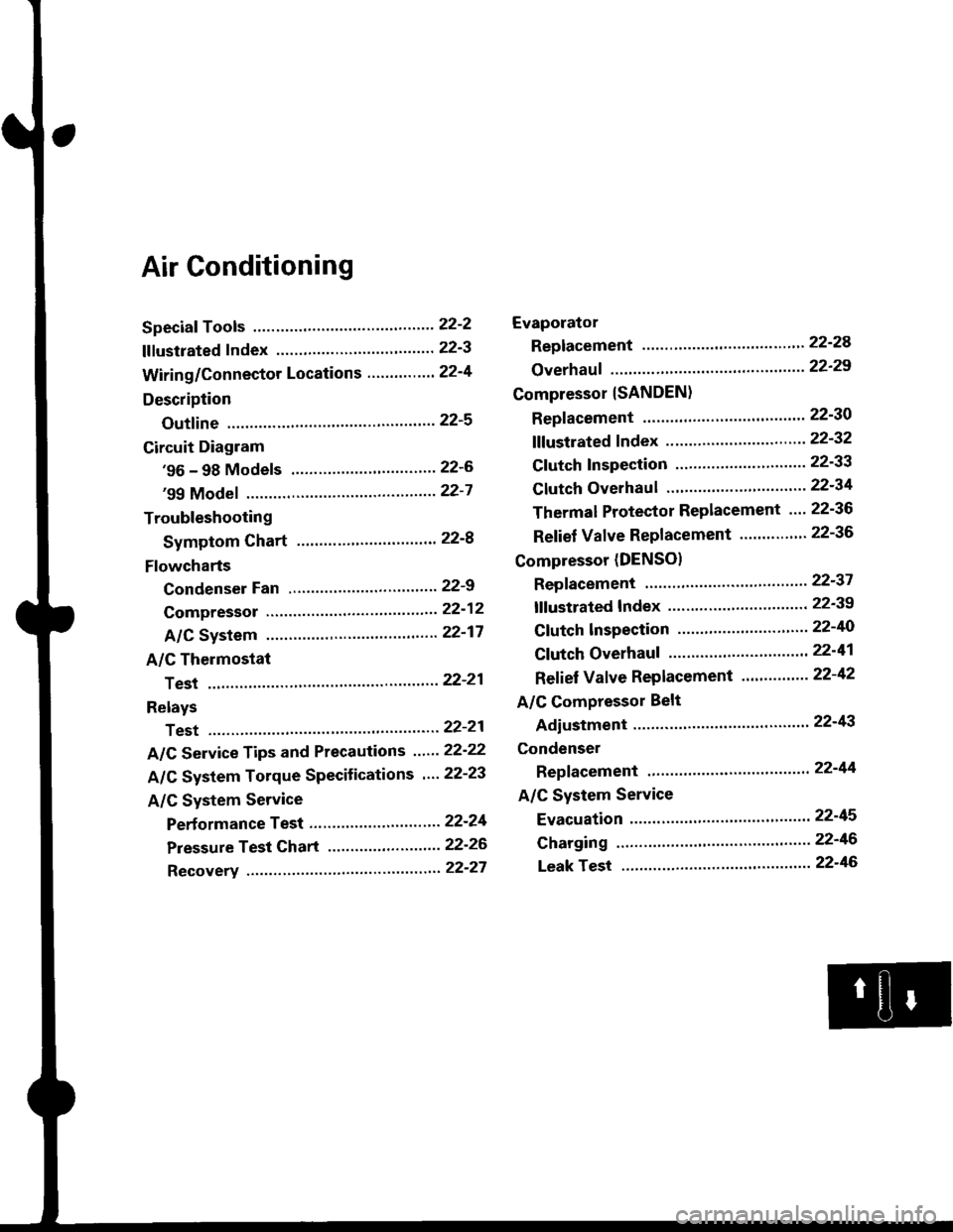
Speciaf Tools ......'.....' 22-2
f f f ustrated f ndex ......................... ".......' 22-3
Wiring/Connector Locations'.........'.... 22'4
Description
Outfine ............ .......22-s
Circuit Diagram
'96 - 98 Models ......"..........".......'.... 22-6
'99 Modef """""""' 22-7
Troubleshooting
Symptom Chart ".'......""................. 22-8
Flowcharts
Condenser Fan .........".................,..'. 22-9
Compressor .....""" 22-12
A/C System .........'.22'17
A/C Thermostat
Test ........'.......' """'22'21
Relays
Test ....."'......... ..""'22-21
A/C Service Tips and Precautions ......22-22
A/C System Torque Specifications '...22-23
A/C System Service
Performance Test ... '."......... ".... ....'..22-24
Pressure Test Chart .................. .... "' 22-26
Recovery ...".........," 22-27
Evaporator
Replacement .....",' 22'24
Overhauf .....-.....""' 22'29
Compressor {SANDEN}
Repf acement ......'.' 22-30
fffustrated fndex ......"..................'.... 22'32
Cf utch Inspection ......... "............ ...... 22-33
Clutch Overhau I ........................ ....... 22-34
Thermal Protector Replacement .... 22-36
Relief Valve Replacement ......'..."". 22-36
Compressor (DENSO)
Repfacement ..""',' 22-37
lf lustrated Index ............................... 22-39
Clutch lnspection ............."'...... "'.... 22-40
Cf utch Overhaul .....................'......... 22-41
Ref ief Valve Replacement'..'......"'.. 22-42
A/C Compressor Belt
Adiustment ............22'43
Condenser
Repfacement .......,,22'44
A/C System Service
Evacuation ...,,,.......22-45
Charging '..........--'..22'46
Leak rest """""""'22-46
Page 1426 of 2189
Special Tools
Bef. No. Tool NumberDescriptionQty I Page Reference
o
@
*07JGG - 00l0l0A
07sAz - 0010004
07947 - 6340300
07965 - 6920500
Belt Tension Gauge
Backprobe Set
Driver Attachment
Hub Assembly Gulde Attachment
1
'1
1
22-43
22-14,16
22-34
22-35' Included in the Belt Tension cauge Set, 07TGG-0010004.
a6r
L
3r
22-2
Page 1454 of 2189
Compressor (SANDENI
Replacement
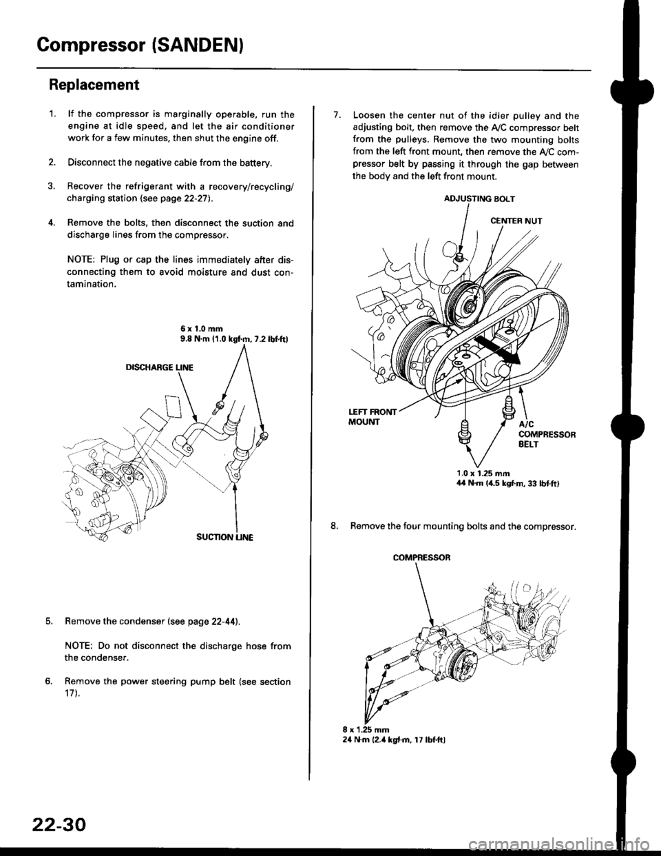
1.lf the compressor is marginally operable, run the
engine at idle speed, and let the air conditioner
work for a few minutes. then shut the engine off.
Disconnect the negative cable from the battery.
Recover the refrigerant with a recovery/recycling/
charging station (see page 22-27l..
Remove the bolts, then disconnect the suction and
discharge lines from the compressor.
NOTE: Plug or cap the lines immediately after dis-
connecting them to avoid moisture and dust con-
tamination.
6xl.0mm
Remove the condenser (see page 22-44).
NOTE: Do not disconnect the discharge hose from
the condenser.
Remove the power steering pump belt (see section
17 t.
22-30
24 N.m l2.ia kgt.m, 17 lbf.ftl
7. Loosen the center nut of the idler pulley and the
adjusting bolt. then remove the A,/C compressor belt
from the pulleys. Remove the two mounting bolts
from the left front mount, then remove the ly'C com-pressor belt by passing it through the gap befiiveen
the bodv and the left front mount.
ADJUSTING BOLT
1.0 x 1.25 mmaa N.m 14.5 kgf,m, 33 bnft)
8. Remove the four mounting bolts and the compressor.
CENTER NUT
COMPRESSOR
Page 1455 of 2189
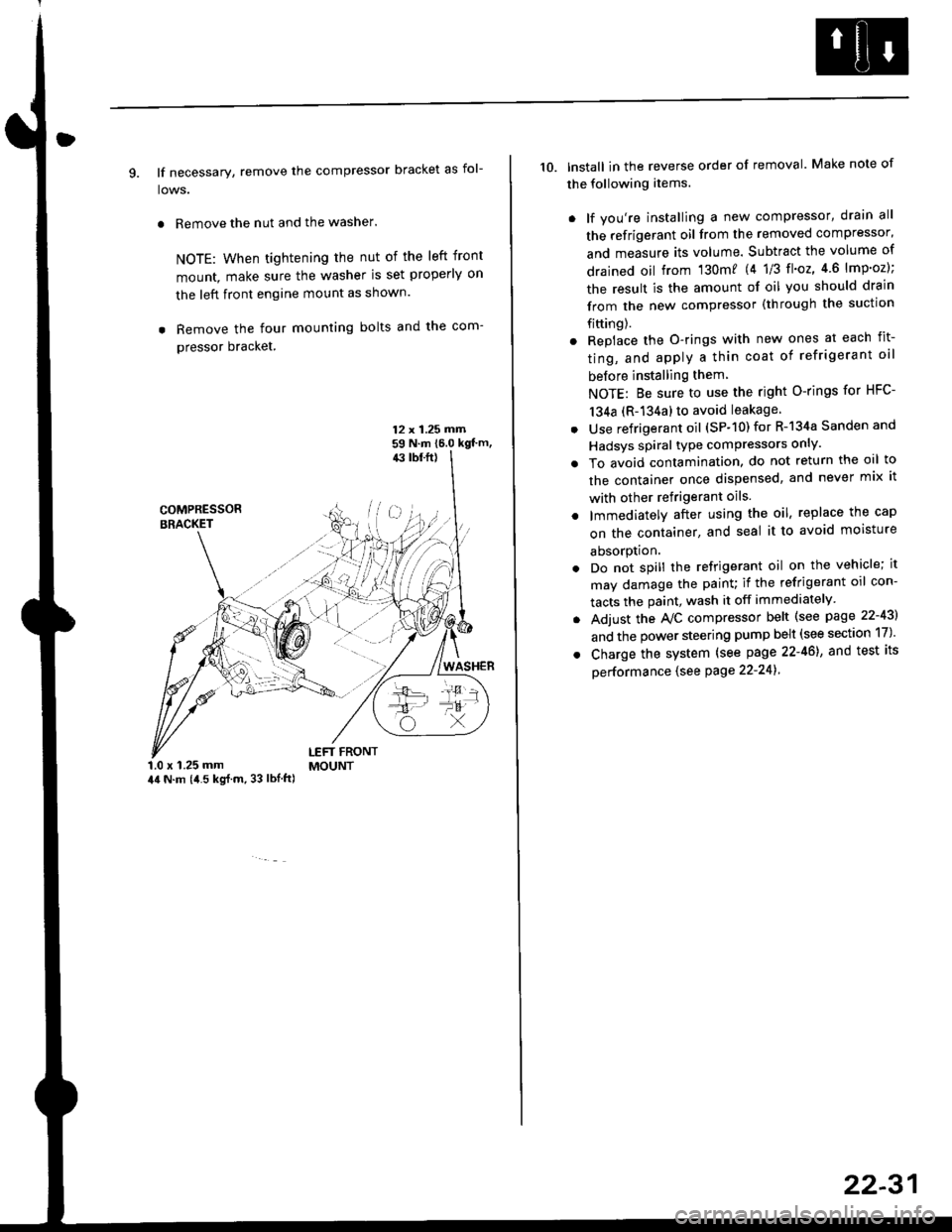
9. lf necessary, remove the compressor bracket as fol-
lows.
. Remove the nut and the washer.
NOTE: When tightening the nut of the left front
mount, make sure the washer is set properly on
the left front engine mount as shown.
. Remove the four mounting bolts and the com-
pressor bracket.
12 x 1.25 rrirn59 N.m 16.0 kgt'm,43 tbf.ft)
COMPRESSORBRACKET
WASHER
1.0 x 1.25 mm44 N.m (i1.5 kg{.m, 33 lbl.ft)
LEFT FRONTMOUNT
10. lnstall in the reverse order of removal. Make note of
the following items.
. lf you're installing a new compressor, drain all
the refrigerant oil from the removed compressor,
and measure its volume. Subtract the volume of
drained oil from '130m? 14 1/3 tl'o2,4 6 lmp'oz);
the result is the amount of oil you should drain
from the new compressor (through the suction
fifting).
. Replace the O-rings with new ones at each fit-
ting, and apply a thin coat of refrigerant oil
before installing them
NOTE: Be sure to use the right O-rings for HFC-
134a (R-134a) to avoid leakage
. Use refrigerant oil (SP-10) for R-134a Sanden and
Hadsys spiral type compressors only'
o To avoid contamination, do not return the oil to
the container once dispensed, and never mix it
with other refrigerant oils.
. lmmediatelY after using the oil, replace the cap
on the container, and seal it to avoid moisture
absorption.
. Do not spill the refrigerant oil on the vehicle; it
may damage the painu if the refrigerant oil con-
tacts the paint, wash it off immediately
. Adjust the Ay'C compressor belt (see page 22-43)
and the power steering pump belt (see section 17)'
. Charge the system (see page 22-46), and test its
oerformance (see Page 22-241
22-31
Page 1458 of 2189
Compressor {SANDEN)
Clutch Overhaul
1. Remove the center nut while holding the armatureplate with the tool.
CENTER NUT17.6 N.m {1.8 kg{.m,'t3 tbnft}
2. Remove the armature plate by pulling it up by hand.
ARMATURE PLATE
A/C CLUTCH HOLDER{Commerciallv aveilable)Robinair: P/N 10204Kent-Moore: P/N J37872
22-34
3. Remove snap ring B with snap ring pliers.
NOTE:
. Be careful not to damage the rotor pulley and
compressor during removal/installation.. Once snap ring B is removed, replace it with anew one.
A
\/
G::.
Remove the rotor pulley from the shaft with a puller
and the special tool.
NOTE: Place the claws of the puller on the back of
the rotor pulley, not on the belt area; otherwise the
rotor pulley can be damaged.
. r \:g2rl -/ /
.-!L;j'/
TWO JAW PULLER{Commercially