1998 HONDA CIVIC Crank shaft
[x] Cancel search: Crank shaftPage 983 of 2189

Transmission
Removal (cont'd)
10. Remove the cotte. pins and castle nuts, then separatethe ball joints from the lower arm (see section 1g).
SELF-LOCKING -=V,
NUT \Replace. oitupea rOax
Remove the right damper fork bolt, then separateright damper fork and damper.
Pry the right and left driveshafts out of the differen-tial.
Pull on the inboard joint to remove the right and leftdriveshafts (see section 16).
Tie plastic bags over the driveshaft ends.
NOTE: Coat all precision finished surfaces with cleanengine oil.
Remove the exhaust pipe A.
/\<,\CASTLE I{UT COTTERReplac6.
't 1.
't2.
tJ.
14.
q.
SELF.LOCKINGNUTReplace.
SELF.LOCKING NUTReplace.
14-306
EXHAUST PIPE A
19.
'16, Remove the right front mounvbracket,
ATF COOLER HOSE
17. Remove the ATF cooler hoses at the ATF coolerlines. Turn the ends of the ATF cooler hoses uo toprevent CVT fluid from flowing out, then plug theATF cooler hoses and lines,
NOTE: Check for any sign of leakage at the hosejoints.
18. Remove the engine stiffeners and the flywheel cover.
Remove the eight drive plate bolts one at time whilerotating the crankshaft pullev.
ENGINE STIFFENER
Page 1025 of 2189
l.
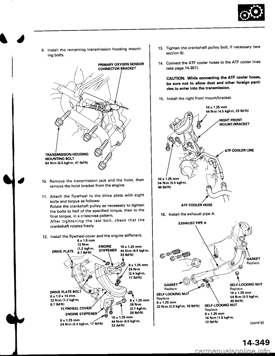
9. Install the remaining transmission housing mount-
ing bolts.
PRIMARY OXYGEN SENSOR
Remove the transmission jack and the hoist. then
remove the hoist bracket from the engine'
Attach the flvwheel to the drive plate with eight
bolts and torque as follows:
Rotate the crankshaft pulley as necessary to tighten
rhe bolts to half of the specified torque, then to the
final torque, in a crisscross pattern.
After tightening the last bolt. check that the
crankshaft rotates freelY.
10.
11.
12. Install the flywheel cover and the engine stiffeners
DRIVE
6xl.0mm12 N.m
- l12 kgf'm'rE 8.7 tbf.ftl
ENGINESTIFfENEB10 x 1.25 mmart N.m la.s kgt.m,33 tbtftt
8 x 1.25 mm24 N.m(2.1 kgf'm,17 tbt.ftt
DRIVE PI.ATE BOLT
6x1.0x14mm12 N.m {1.2 kgt m.
8.7 lbf,ftl8 x 1.25 mm26 N.m
12.7 kqfin,20 rbt'ftlFLYUTHEEL
ENGINE STIFFENER
8 x 1.25 mm10 x 1.25 mmr,a N.m {4,5 kgf m,
33 tbf.ftl
TRANSMISSION HOUSING
MOUNNNG BOLT
6il N.m {6.5 kgf.m, 47 lbf'ftl
24 N.m (2.4 kgt'm, '17 lbf'ftl
22 N.m t2.2 kgl m, 16lbf'ftl
14-349
13.
14.
Tighten the crankshaft pulley bolt, if necessary (see
section 6).
Connect the ATF cooler hoses to the ATF cooler lines
(see page 14-357).
CAUTION: Whilo connecting the ATF cooltr hGes,
b€ sure not lo allow dust and other loreign parti-
cles to entg. into the transmission.
15. Installthe right front mounvbracket'
10 x 1.25 mm
a,r N.m {4.5 kgf'm,33 lbt ftl
RIGHT FRONTMOUNT/BRACKET
ATF COOLER LINE
10 x 1 .25 mm54 N.m {5.5 kgt'm,
4{) tbl.ftt
ATF COOI,TR HOSE
16. Installthe exhaust PiPe A.
EXHAUST PIPE A
GASKETReplace.
@
\SELF.LOCKING NUTReplace.10 x 1.25 mm5/a N.m {5.5 kgt m,irc lbf.ft)
(cont'dl
*s$o
oor*rr-@Replace.
SELF.LOCKINGReplace.8 x 1.25 mmSELF.LOCKING NUT
Replace.8 x 1.25 mm16 N.m {1.6 kgl'm,12 tbl.ftt
Page 1073 of 2189
)
Steering Pump
Construction
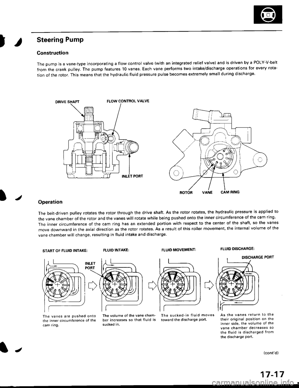
The pump is a vane-type incorporating a flow control valve (with an integrated relief valve) and is driven by a POLY-V-belt
from the crank pulley. The pump features 10 vanes. Each vane performs two intake/discharge operations for every rota-
tion of the rotor. This means that the hydraulic fluid pressure pulse becomes extremely small during discharge.
/
ROTORVANE CAM RING
Operation
The belt-driven pulley rotates the rotor through the drive shaft. As the rotor rotates, the hydraulic pressure is applied to
the vane chamber of rhe rotor and the vanes will rotate while being pushed onto the inner circumference of the cam ring.
The inner circumference of the cam ring has an extended portion with respect to the center of the shaft, so the vanes
move downward in the axial direction as the rotor rotates. As a result of this roller movement. the internal volume of the
vane chamber will change, resulting in fluid intake and discharge
START OF FLUID INTAKE:FLUID INTAKE:FLUID MOVEMENT:FLUID DISCHARGE:
The vanes are pushed ontothe inner circumference ol the
cam ring,
lhe volume ofthe vane cham- The sucked-in fluid moves
ber increases so that fluid is toward the discharge port.
sucked in.
As the vanes return to the
their original Position on theinner side, the volume of the
vane chamber decreases so
the fluid is discharged from
the discharge port.
(cont'd)
a-t 4-I I- | t
FLOW CONTROL VALVE
J
Page 1088 of 2189
Inspection and Adjustment
Pump Belt
NOTE: When using a new belt, first adjust the deflection
or tension to the values for the new belt, then readjust
the deflection or tension to the values for the used beltafter running engine for five minutes.
Inspection
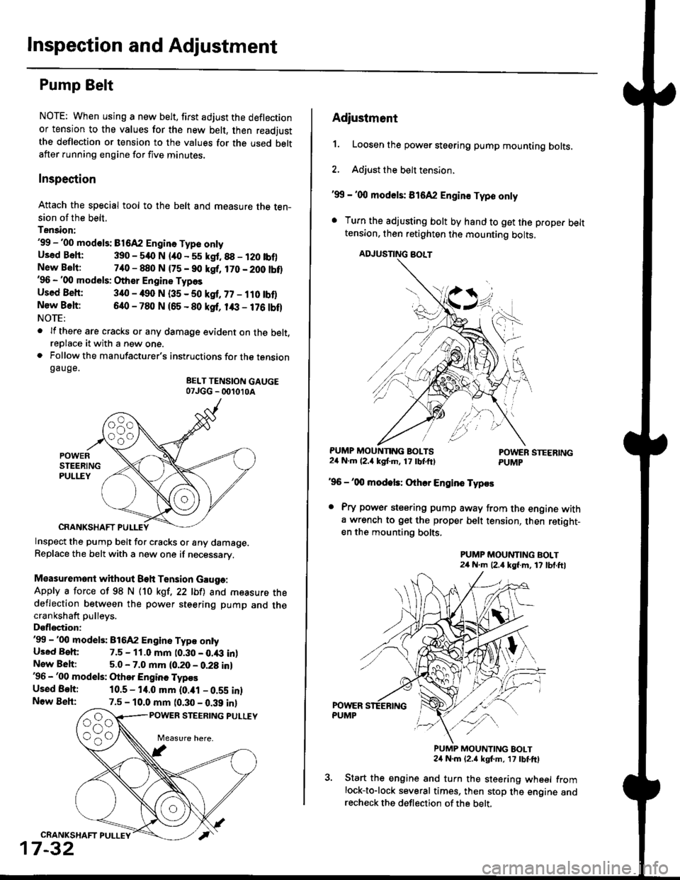
Attach the special tool to the belt and measure the ten-sion of the belt.
Tension:'99 -'00 mod€ls: B1642 Engin. Type onlyUsed Bsh: 390 - 540 N lao - 55 kgt.88 - 120 tbf)New Belt:740 - 880 N {75 - 90 kgf, 170 - 200 tbt}'96 - '00 models: Other Engine Types
Used Beh: 340 - 490 N (35 - 50 kgf, 77 - ilO tbflNew Belt:640 - 780 N 165 - 80 ksf, 1& - 176 tbf)NOTE:
. lf there are cracks or any damage evident on the belt,reDlace it with a new one.. Follow the manufacturer's instructions for the tensiongauge.
BELT TENSION GAUGE07JGG _ 001010A
Inspect the pump belt for cracks or any damage.Replace the belt with a new one if necessary.
Measuremont without Beh Tension Gauga:
Apply a force of 98 N (10 kgt,22 lbfl and measure thedeflection between the power steering pump and thecrankshaft pulleys.
Dsflectior:'99 -'00 model3: 816A2 Engine Typ€ ontyUsed Beh: 7.5 - 11.0 mm t0.30 - 0.43 inlNew Beh:5.0 - 7.0 mm (0.20 - 0.28 in)'96 - '00 models: Othor Engine Typos
Used Behi 10.5 - 14.0 mm (0.ial - 0.59 inlNow Beh:7.5 - 10.0 mm (0.30 - 0.39 inl
POWER STEERING PULUY
CRANKSHAFT PULLEY
17-32
Adiustment
1. Loosen the power steering pump mounting bolts.
2. Adjust the belt tension.
'99 - '00 mod€ls: 816A2 Engin€ Typo only
. Turn the adjusting bolt by hand to get the proper belttension, then retighten the mounting bolts,
ADJUSNNG BOLT
PUMP MOUNNNG BOLTS24 N.m (2.4 kgf'm, 17 tbtftlPOWER STEERINGPUMP
'96 -'00 modek: Othcr Engins Typos
. Pry power steering pump away from the engine witha wrench to get the proper belt tension, then retight-en the mounting bolts.
PUMP MOUNTING BOLT24 N.m (2,4 kgf.m, 17 lbl.ftl
PUMP MOUNTING BOLT24 N.m {2.a kgt m, 17 tbtftl
Start the engine and turn the steering wheel fromlock-to-lock several times, then stop the engine andrecheck the deflection of the belt,
Page 1467 of 2189
A/G GomPressor Belt
Adjustment
Detlection Method
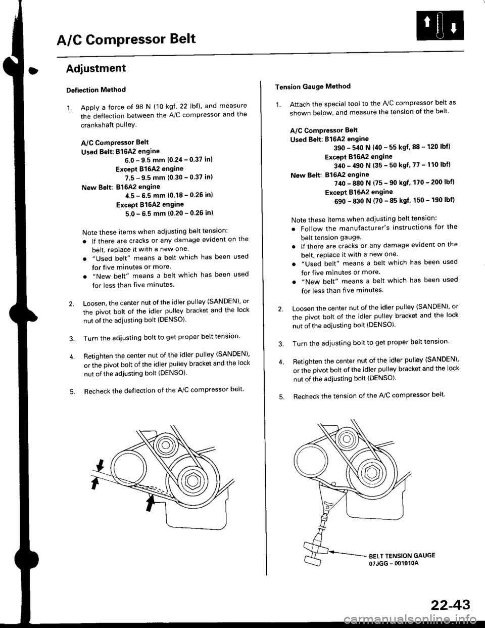
'1. Apply a force of 98 N (10 kgf, 22 lbf), and measure
the deflection between the A,/C compressor and the
crankshaft PulleY
A/C ComPressor Belt
Used Belt: 816A2 engine
6.0 - 9.5 mm 10 2'l - 0.37 inl
Except 816A2 engine
7.5 - 9.5 mm (0.30 - 0.37 in)
New Belt: 816A2 engine
4.5- 6 5 mm (0.18-0.26 in)
Except 815A2 engine
5.0-5 5 mm (0.20-0.26 inl
Note these items when adjusting belt tens'on:
. lf there are cracks or any damage evident on the
belt, replace it with a new one.
. "Used belt" means a belt which has been used
for five minutes or more.
. "New belt" means a belt which has been used
tor less than five minutes.
2. Loosen, the center nut ofthe idler pulley (SANDEN), or
the pivot bolt of the idler pulley bracket and the lock
nut ofthe adjusting bolt (DENSO).
3. Turn the adjusting bolt to get proper belt tension'
4. Retighten the center nut of the idler pulley (SANDEN),
or the pivot bolt of the idler pulley bracket and the lock
nut of the adjusting bolt (DENSO).
5. Recheck the deflection of the A,/C compressor belt'
Tension Gauge Method
1. Attach the special tool to the IVC compressor belt as
shown below, and measure the tension of the belt
A/C Compressor Belt
Used Belt: 816A2 engine
390 - 540 N (40 - 55 kgf, 88 - 120 lbll
Except 816A2 engine
340 - 490 N (35 - 50 ksf, 77 - 110 lbfl
New Belt: B16A2 engine
?40 - 880 N {75 - 90 ksf' 170 - 200 lbf)
Except Bl642 engine
690 - 830 N (70 - 85 ksf, 150 - 190 lbf)
Note these items when adjusting belt tension:
. Follow the manufacturer's instructions for the
belt tension gauge.
. lf there are cracks or any damage evident on the
belt, rePlace it with a new one.
. "Used belt" means a belt which has been used
for five minutes or more.
. "New belt" means a belt which has been used
for less than five minutes
2 Loosen the center nut of the idler pulley (SANDEN)' or
the pivot bolt of the idler pulley bracket and the lock
nut of the adjusting bolt (DENSO).
3. Turn the adjusting bolt to get proper belt tension
4. Retighten the center nut of the idler pulley (SANDEN),
or the pivot bolt of the idler pulley bracket and the lock
nut of the adjusting bolt (DENSO)
5. Recheck the tension of the A/C compressor belt'
22-43
Page 1486 of 2189

Connector ldentification and Wire Harness Routing
Engine Wire Harness lD16Y5, D16Y8 enginss): '96 - 98 models
Connector or
Torminal
Numbsr of
CavitissLocationConnects toNot€s
c 101c102c103c104c104c105c106c107c108c 109c110c111c112c113c114c115c116cl17c118c119c120cl21
c122c123cl23c124
c125
c127c12Ac129c130c131c132c 133c134c135
c136
c138c139c140c 141c142c 143c144cl44c145c'146cl47
10
1
22
14l4322l0I
2
2
2
2120
3l
14
14
1222
2
2
22
Left side of engine compartmentMiddle of engineMiddle of engineLeft side of engine companmentLeft side of engine compartmentMiddle of engineMiddle of engineMiddle of engineMiddle of engineMiddle of enginefvliddle of engineMiddle of engineMiddle of engineMiddle of engineMiddle of engineMiddle of engineMiddle of engineLeft side of engine compartmentMiddle of engineMiddle of engineMiddle of engineMiddle of engine
Middle of engineMiddle of engineMiddle of engineMiddle of engineMiddle of engineMiddle of engineMiddle of engineMiddle of engineMiddle of engineRight side of engine companmentBehind right kick panelUnder right side of dashUnder riOht side of dashUnder right side of dashUnder right side of dashUnder right side of dashUnder right side of dash
Under right side of dash
Under right side of dash
Middle of engineMiddle ot enginel iddle of engineMiddle of engineMiddle of ongineMiddle of engineLeft side of engine compartmentMiddle of engineMiddle of engineRight side of engine compartmentRight side of engine compartmentRight side of engine compartment
USACanada
Afi
USA
-' (A/r)
Main wire harness (C303)Crankshaft speed fluctuation (CKF) sensorEngine oil pressure switchAlternatorAlternatorNo. 'l fuel injectorNo. 2 fuel injectorNo.3 fuel injectorNo. 4 fuel injectorIAC valveThrottle position (TP) sensorl\4anifold absolute pressure (MAP) sensorIntake air temperature (lAT) sensorPower steering pressure {PSPI switchEVAP purge control solenoid valveJunction connectorJunction conn€ctorVehicle speed sensor {VSS}Countershaft speed sensorEngine coolant temp€rature (ECT) switch ADistributorEngine coolant temperature (ECT) sendingunrtEngine coolant temperature (ECT) sensorPrimary HO2S (sensor'l)Primary HO2S (sensor 1)Back-up light switchLock-up control solenoid valveSecondary HO2S (sensor 2)Mainshaft speed sensorLinear solgnoid valveShift control solsnoid valveStarter solenoidJunction connectorMain wire harnesE (C446)ECM/PCMPCMECMiPCMECM/PCMMain wire harness (C305)
Main wire harness (C305)
Main wire harness (C305)
Knock sensor (KS)IAC valveVTEC solenoid valveVTEC pressure switchEVAP control canister vent shut valveEGR control solenoid valveSecondary gear shaft speed sensorEGR valveEGR valveDrive pulley speed sensorSolenoid connector {CVT)Driven pulley speed sensor
*, (M/T)M/T*" INT\
*, tAtf)
NT:'96 model*,(A,/T):'97 - 98mooets
moqets
M/T
-1 (l,/T)*, (A,/T)-,(4,/T)*1 {M/T)*, (A,/T)*1 (CW)*, (A,T)
T101r102Left side of engine companmentRight side of engine companmentAlternatorUnder-hood fuse/relay boxG 101Middle of engineEngine ground, via engine wire harness
2
*1: Dl6Y5 engine*2: D16Y8 engine*3: D16Y5 (Ay'T), D16Y8 engines
3-16
Page 1488 of 2189
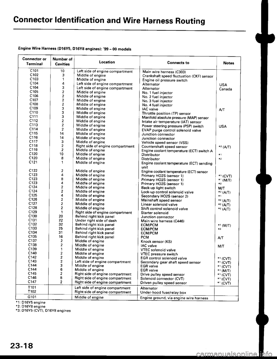
Gonnector ldentification and Wire Harness Routing
Engine Wire Harness (D16Y5, Dl6Yg engines): ,99 - 00 models
Connectot or
Terminal
Number ot
CavitiesLocationConn€cts toNotes
c'101cl02c103c104c 104c10s
c107c 108c'r09c110c111cl12c113cl14c l15c116cl17c118c119c120cl20c121
c122c123c123cl23cl24c124c125
c127c12Ac129c 130c131cl32c133c 134c135c137c138c 139c 140c142c143c144cl44c145c146c147
103,]
322223332221414322'10
8,l
2484224222120
32
2212223
282
No. 1 luel injector INo.2 fuel injectorNo.3 fuel injector ]No. 4 fuel injector iIAC valve I anThrottle position lTP) sensorManifold absolute pressure {MAP) sensor IIntake air temperature (lAT) sensor IPower steering pressure (PSP)switch USAEVAP purge control solenoid valve ]
Main wire harness 1C303)Crankshaft speed fluctuation (CKF) sensorEngine oil pressure switchAlternatorAlternator
Left side ot engine compartmentlvliddle of engineMiddle of engineLeft side ot engine compartmentLeft side of engine compartmentMiddle of engineMiddle ot engineMiddle of engineMiddle of engineMiddle oI engineMiddle of engineMiddle of engineMiddle of engineMiddle of engineNliddle of engineMiddle of engineMiddle of engineMiddle of engineRight side of engine compartmentMiddle of engineMiddle of engineN4iddle of engineMiddle of engine
Middle of engineMiddle ot engineMiddle ot engineMiddlo of engineMiddle of engineMiddle ot enginelrliddle of engineMiddle of engineMiddle oI engineMiddle ot engineRight side of engine compartmenlBehind right kick panelUnder right side of dashBehind right kick panelBehind right kick panelBehind righr kick panelBehind right kick panelMiddle ot engine[,liddle of engineN4iddle of engineMiddle of engineMiddle oI engineLeft side of engine compartmentMiddle of engineMiddle of engineRight side ol engine compartmentRight side of engine companmentRight side of engine compartment
USACanada
Junction connectorJUnct|On COnnectorVehicle speed sensor lVSS)Countershaft speed sensorEngine coolant temperature {ECT} switch ADistributorDistributorEngine coolant temperature (ECT) sendingunitEngine coolant temperature (ECT) sensorPrimary H02S (sensor 1)Primary HO2S (sensor 1)Primary HO2S lsensor 1)Back-up light switchLock'!p control solenoid valveSecondary HO2S (sensor 2)Mainshaft speed sensorLinear solenoid valveShift control solenoid valveStarter solenoidJunction connectorMain wire harness (C446)ECM/PCMECM/PCMECM/PCMPCtvtKnock sensor (KS)IAC valveVTEC solenoid valveVTEC pressure switchEGR control solenoid valveSecondary gear shaft speed sensorEGR valveEGR valveDrive pulley speed sensorSolenoid connector (CVT)Driven pulley speed sensor
*'� (A/TI
*1 (CVT)*, (M/T)
Mfia (A/Tl
" (A,/T)., (4,/r)-'� {AlrJ
*1 (M/T)
tvliT
*1 (CVT)*, (cvT)*' (cw)*1 (MiT)*1 {CVT)*1 {CVT)*, (cvr)
T101T102Left side of engine companmentRight side ot engine companmentAlternatorUnder'hood fuse/relay boxG 101Middle of englne IEngine ground, via engine wire harness*1: 016Y5*2: D16Y8*3: Dl6Y5
engineengine(CW), D16Y8 engines
23-14
Page 1490 of 2189
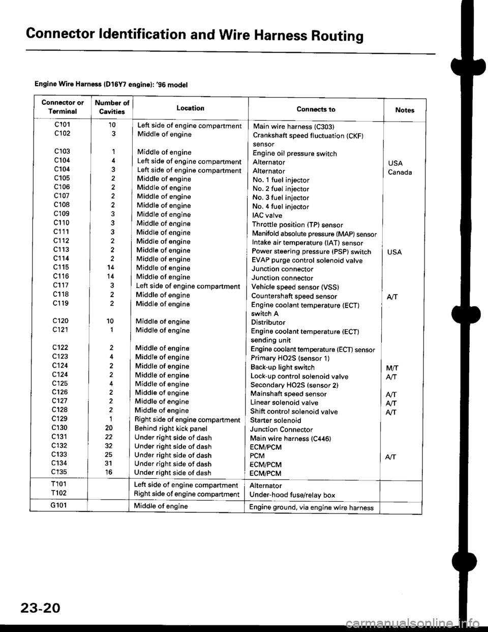
Gonnector ldentification and Wire Harness Routing
Engine Wire Harness {D16Y7 engine}: '96 model
Conneclor or
Terminal
Number ot
CavhiesLocationConnects toNotes
c101
c102
c 103
c104
c104
c105
c'r06
c107
c 108
c 109
c110
c111
c112
c l13
c't14
LttS
cl16
cl17
c118
cl19
c120
c121
c123
c124
c124
c125
c126
c't27
c12a
c129
c130
c131
c132
c133
c134
c135
10
1
4
5
'14
14
10
1
,,
2
2
1
22
31
16
No. 1 fuel injector INo. 2 fuel injector
No. 3 fuel injector INo,4 fuel injector
IAC valve l
Throttle position (TP)sensor IManifold absolute pressure (MAP) sensorIntake ai. temperature (lAT) sensor ]Power steering pressure (PSP) switch I USAEVAP purge control solenoid valve IJunction connector
Junction connector IVehicle speed sensor (VSS) |Countershaft speed sensor AlTEngine coolant temperature (ECT) I
Main wire harness (C303)
Crankshaft speed fluctuation (CKF)
sensor
Engine oil pressure switch
Alternator
Alternator
switch A
Distributor
Engine coolant temperature (ECT)
sending unit
Engine coolant temperature lECT) sensor
Primary H02S (sensor 1)
Back-up light switch
Lock-up control solenoid valve
Secondary HO2S (sensor 2)
Mainshaft speed sensor
Linear solenoid valve
Shift control solenoid valve
Staner solenoid
Junction Connector
Main wire harness {C446)ECM/PCM
PCM
ECM/PCM
ECM/PCM
Left side of engine compartment
Middle of engine
Middle of engine
Left side of engine compartment
Left side of engine compartment
Middle of engine
Middle of engine
Middle of engine
Middle of engine
Middle of engine
Middle of engine
Middle of engine
Middle of engine
Middle of engine
Middle of engine
Middle of engine
Middle of engine
Left side of engine compartment
Middle of engine
Middle of engine
Middle of engine
Middle of engine
Middle of engine
Middle of engine
Middle of engine
Middle of engine
Middle of engine
Middle of engine
Middle of engine
Middle of engine
Right side of engine compartment
Behind right kick panel
Under right side of dash
Under right side of dash
Under right side of dash
Under right side of dash
Under right side of dash
USA
Canada
M/T
AtJ
Afi
T101
T102
Left side of engine compartment
Right side of engine compartment
Alternator
Under-hood fuse/relay box
G101Middle of engineEngine ground, via engine wire harness
23-20