Page 1285 of 2189

L
L
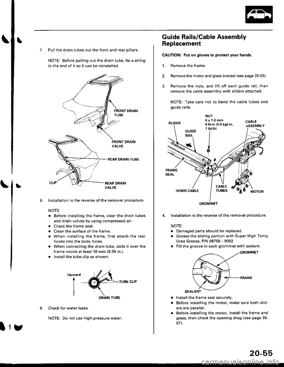
7. Pull the drain tubes out the front and rear pillars.
NOTE: Before pulling out the drain tube, tie a string
to the end of it so it can be reinstalled.
Installation is the reverse of the removal procedure.
NOTE:
. Before installjng the frame, clear the drain tubes
and drain valves by using compressed air.
. Check the frame seal.
. Clean the surface of the frame.
. When installing the frame, first attach the rear
hooks into the body holes.
. When connecting the drain tube, slide it over the
frame nozzle at least 10 mm (0.39 in.).
. Install the tube clip as shown.
UpwardI
I
I
TUBE CLIP
Check for water leaks.
NOTE: Do not use high-pressure water.
DRAIN TUBE
Ity
20-55
Guide Rails/Cable Assembly
Replacement
CAUTION: Put on gloves to protect your hands,
1. Remove the frame.
Remove the motor and glass bracket (see page 20-52).
Remove the nuts, and lift off each guide rail, then
remove the cable assembly with sliders attached.
NOTE: Take care not to bend the cable tubes and
guide rails.
Installation is the reverse of the removal procedure.
NOTE:
. Oamaged parts should be replaced.
. Grease the sliding portion with Super High Temp
Urea Grease, P/N 08758 - 9002.
. Fillthe groove in each grommet with sealant.
a
a
Install the frame seal securely.
Before installing the motor. make sure both slid-
ers are parallel.
Before installing the motor. install the frame and
glass, then check the opening drag (see page 20-
GROMMET
Page 1287 of 2189

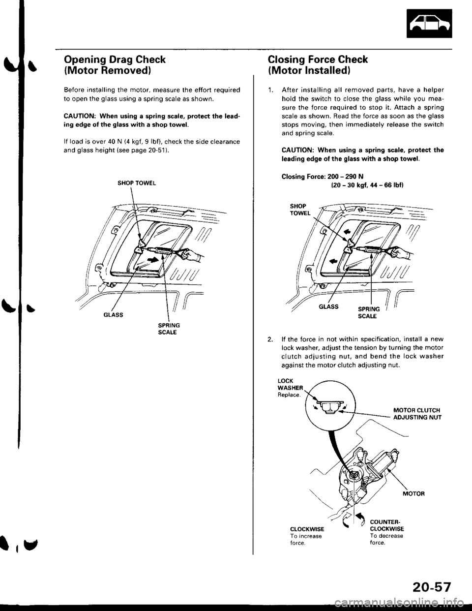
Opening Drag Check
{Motor Removed)
Before installing the motor, measure lhe effort required
to open the glass using a spring scale as shown.
CAUTION: When using a spring scale, pfotest the lead-
ing edge ol the glass with a shop towel.
lf load is over 40 N (4 kgf,9 lbf), check the side clearance
and glass height (see page 20-51).
SHOP TOWEL
l,e
20-57
Closing Force Check
(Motor Installedl
'1. After installing all removed parts, have a helper
hold the switch to close the glass while you mea-
sure the force required to stop it. Attach a spring
scale as shown. Read the force as soon as the glass
stops moving, then immediately release the switch
and spring scale.
CAUTION: When using a spring scale, protect the
lerding edge ol the glass with a shop towel.
Closing Force: 200 - 290 N(20 - 30 kst, 44 - 66 lbfl
lf the torce in not within specification, install a new
lock washer, adjust the tension by turnang the motor
clutch adjusting nut, and bend the lock washer
against the motor clutch adjusting nut.
LOCKWASHERReplace.
COUNTER.cLocKwrsETo decrease
SCALE
Page 1337 of 2189
Opener Cable/Opener and Latch/Wiper and Washer
Component Location Index
2Dt3DItD'
y"Tl,"nll,ib?*'r.* o*t"
Replacement, Page 20_1 13
Adiustment, Page 20'1 17
WINDSHIELDWASHER NOZZLESAdjustment, Page 20_1 17
HOOD LATCH
{see page 20-110)
REAR WINDOW WIPER
ARM and MOTORReplacement, Page 20-1 15
Adjustment, page 20 117
LOCK CYLINDER(see page 20 113)
LOCK CYLINDER
TRUNK LIO LATCH
{see page 20 112)
FUEL LID OPENERCABLE(see page 20-108i
LID OPENERCABLE(see page 20 108)
LID/FUELLID OPENER(see page 20 111)
RELEASE HANDLE(see page 20-110)
3D:
REAR WINDOWWASHER NOZZLEAdiustment, page 20-1 17
REAR WINDOWWASHER TUBE(see page 20-116)
HATCH OPENERCABLE(see page 20 110)
WASHER RESERVOIRReplacement, Page 20-1 15
HATCH/FUEL LID OPENER(see page 20 1'11)
FUEL LID OPENERCABLE(see page 20 110)
(see page 20 111)
20-107
Page 1344 of 2189
Windshield Wiper Arms and Linkage
Replacement (cont'dl
USA-produced:
3. Separate the windshield wiper linkage and wind-
shield wiper motor.
Japan/Canada-produced:
NOTE: Scribe a line across the link and windshield
wiper linkage to show the original adjustment.
>: Bolt locations, 3
O 6r1.0mm
EF 8 N.m {0.8 kstm,ig 5.8 tbf.ft) )
NUT10 x 1.25 mml8 N rn (1.8 kgtm,13 tbtftl
>r Bolt locations,3
WIPER LINKAG€
\
20-114
USA-produced:
NOTE: Scribe a line across the link and windshield
wiper motor to show the original adjustment.
>: Bolt locations, 2
R 6J( 1.0 mm
Y 8 N.m to.s kgtm, I
.E- 7Y.nt )
NUT10 x 1.25 mm'18 N.m {1.8 kgf.m.13 tbtft)
WINDSHIELDWIPER MOTOR
4. Installation is the reverse of the removal procedure.
NOTE:
. Make sure the connector is connected properly.
. lf necessary, replace any damaged clips.
. lnstall the windshield wiper arms as described
on page 20-1'17.
. Check the windshield wiper motor operation.. Grease the moving parts.
Page 1345 of 2189

Rear Window Wiper
Arm and MotorWasher Reservoir
Replacement
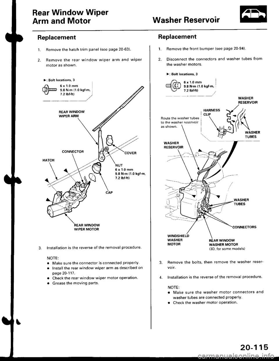
't.
2.
Remove the hatch trim panel (see page 20 63).
Remove the rear window wiper arm and wiper
motor as shown.
Installation is the reverse of the removal procedure
NOTE:
. Make sure the connector is connected properly
.Install the rear window wiper arm as described on
page 20-117.
. Check the rear window wiper motor operation.
. Grease the moving parts.
3.
NUT6x1.0mm9.8 N.m 11.0 kgf.m,7.2 tbf.ft)
WIPER MOTOR
L
2.
Replacement
Remove the front bumper (see page 20-94).
Disconnect the connectors and washer tubes from
the washer motors.
>: Bolt locations,3
/)^ 6xt.omm
Ql(S) s.e ru.- tt.o ret '".\./ 7 .2 tbf.ft) /
Route the washer tubes10 the washe. reservoir
wtNDowWASHER MOTOR(3D, for some models)
Remove the bolts, then remove the washer reser-
voir.
Installation is the reverse of the removal procedure.
NOTE:
a Make sure the washer motor connectors and
washer tubes are connected properly.
. Check the washer motor operation.
3.
4.
20-115
Page 1359 of 2189
Washer Tube
Replacement (cont'dl
NOTE: To remove the rear window washer tube (3D), remove the following parts from the left side of the vehicle.
- Inner fender (see page 20-'106)- Kick panel and side trim (see page 20-60)- Rear seat-back and rear seat cushion (see page 20-80)- Spare tire lid- Rear center shelf and rear side shelf (see page 20-60)- Rear trim panel and side trim panel (see page 20-60)- Ouarter trim panel (see page 20-60)- Rear roof trim (see page 20-65)- Hatch spoiler (see page 20-1011
>: Washer nozzle, clip and cushion locationsA >.9 B>,2 C>, 1
I sl -..._, 1
aj\
_ ____/ _>_t _ _/
(see page 20 101).
REAR WINDOWWASHER TUBE(for some models)
Installation is the reverse ofthe removal procedure.
NOTE:
. Take care not to pinch the washer tubes.
. lf necessary, replace any damaged clips.
. After installing, adjustthe aim ofthe washer nozzles (see page2O-1111.
motor.
20-130
Page 1375 of 2189

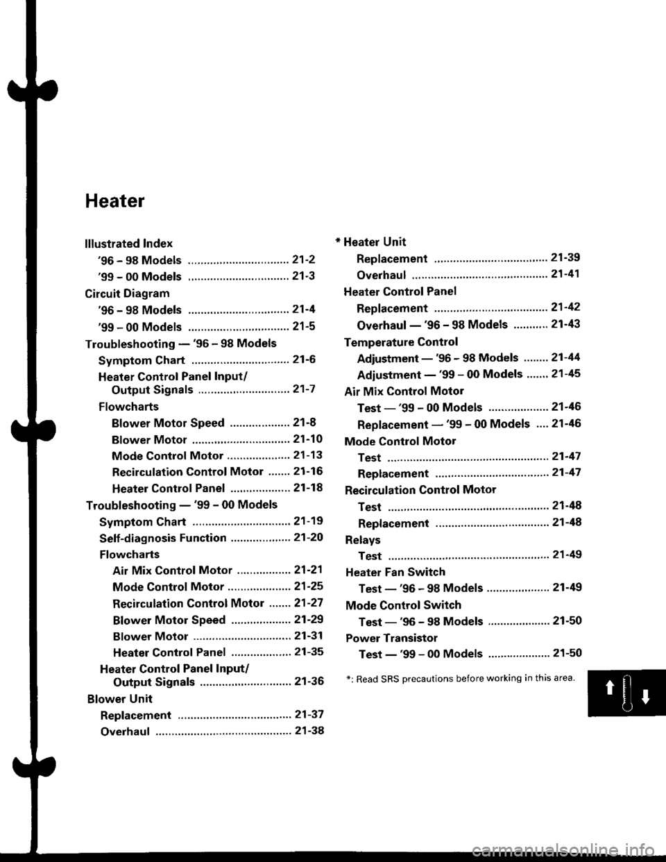
Heater
lllustrated Index
'96 - 98 Models ................................ 21'2
'99 - 00 Models ................................ 21'3
Circuit Diagram
'96 - 98 Models .....21-4
'99 - 00 Models ................................ 21-5
Troubleshooting - '96 - 98 Models
Symptom Chart ............................... 21-6
Heater Control Panel Input/
Output Signals ..............,.............. 21-7
Flowcharts
Blower Motor Speed ................... 21-8
Bf ower Motor ,...21'10
Mode Control Motor ............... ,.'.' 21-13
Recirculation control Motor ....... 21-16
Heater Control Panel ................ ... 21 -14
Troubleshooting - '99 - 00 Models
Symptom Chart ............................... 21-19
Seff-diagnosis Function ............,,,.... 21-20
Flowcharts
Air Mix Control Motor ......,.......... 21-21
Mode Control Motor ............... ..... 21 -25
Recirculation Control Motor ....... 21-27
Bf ower Motor Speed .............. .....21'29
Bf ower Motor ....21-31
Heater Control Panel ................,.. 21-35
Heater Control Panel Input/
Output Signals ............................. 21-36
Blower Unit
Repf acement .........21-37
Overhaul ................ 21-38
* Heater Unit
Replacement ....'....21-39
overhaul """" """' 21-4'l
Heater Control Panel
Repfacement .........21'42
Overhaul -'96 - 98 Models ........... 21-43
Temperature Control
Adjustment - '96 - 98 Models """" 21-44
Adiustment - '99 - 00 Models .......21-45
Air Mix Control Motor
Test - '99 - 00 Models ...........' .......21'46
Replacement - '99 - 00 Models ....21'46
Mode Control Motol
Test ................, .,...'.21'47
Replacement '.'."...21-47
Recirculation Control Motor
Test ................. .......21-48
Repf acement ......." 21-48
Relays
Test ................. .......2'l-49
Heater Fan Switch
Test - '96 - 98 Models ............. .......21-49
Mode Control Switch
Test -'96 - 98 Models ..........."....... 21-50
Power Transistor
Test - '99 - 00 Models ....'........ ....".21-50
*: Read SRS Drecautions before working in this area.
Page 1376 of 2189
lllustrated Index
'96 - 98 Models
SRS components are located in this area. Review the SRS component locations, precautions, and procedures in the SRS
section {24) before performing repairs or service.
BLOWER UNITReplacement, page 21-37Overhaul, page 21-38
HEATER UNITBeplacement, page 21-39Overhaul, page 21-41BLOWERRESISTOBTest,
CONTROL MOTORTest, page 21-48Replacement, page 21'48
a/c swtTcH{wirh A/c)
MOO€MOTORTest, page 21 47Replacement, page 21'47
AIR MIX CONTROL CABLEAdjustment, page 2'1-44Replacement, page 21'43
HEATER FANswtTcHTest, page 2l'49
MODEHEATER CONTBOLPANELswrTcHEsTest, page 21 50Rgplacement, page 2'l-42Overhaul, page 21-43
TEMPERATURE CONTROLLEVERAdiustment, page 21 44
Detroster-aqtivated A/C System
Turning the defroster on activates the A,/C and sets the air flow mode to FRESH. lt is possible to turn the A,/C off or to
change the air flow to RECIRCULATE by pressing the A/C bunon or the FRESH/RECIRCULATE button.
21-2