1998 HONDA CIVIC Tune up
[x] Cancel search: Tune upPage 361 of 2189

Troubleshooting
Engine/P_o,wertrain Control Module Terminal Arrangement('99 - 00 Models except Dl6Y5 engine with M/Tl
ECM/PCM CONNECTOR A (32P)Wire side ot temale terminalsNOTE:Standard battery voltage is l2 V
ECM/PCM CONNECTOR A I32PI
Sign!l
3BLU2WSS (EVAP 8YPAsS SOLENOIDDrives EVAP bypass solenoid vatve,With gn'tion swnch ON (lll banery votlage
LT GRN/I/VIITVSV {EVAP CONTNOL CANISTERVENTSHUTVALVE]Drives EVAP controt ca n isrer v€nt shutWilh ignilion switch ON {tl): b€ttery vottage
8LU/GNNC8S (CRUISE CONTSOL SIGOown shift signal inpot lrom c.uise conrrolWhen crurss control is used:purses
68ED/YELPCS {EVAP PURGE CONTROLSOTENOIOVALVE)Drives EVAP purge conrrol sotenoid vatve.With engine running, engine cootant, betow r54.F (6a,C):
With engine.unning, €ngine coolant, abov€ 154.F(68'C): duty conlrolled
YELATPD {AT GEAR POSITIONSWITCH)ootects A/T gear posnion swilch s,gnar.In otherthan @ posilion: Apprcx. 5 V
8BLK,IflHTSO2SHTC (SECONDARY HEATED OXYGEN SENSOS HEATEFCONTFOL)
Drives sscondary h€ared oxygen senso.Wilh isn,rion swirch ON (ll):banery votraseWith lully warm6d dp€ngire runn'ng:dury controled
LT GRNATPNP (AT GEAF POSITIONSWITCH)oereds A/T 9€a r position switch signat.In Parr or neulrsl:0 VIn anyother position approx.5 v
t088NSCS (SERVICE CHECK SIGNAL)Oetects ssruice check connecror signal(the signalcausing a OTC indication)with rh€ t6rminal connected: 0 vWith the rerm ina I disconneded: abour 5 V of ban€ry
GNN/BIKD4IND (D4INDICATON]Drives Oa indicaio. lighr.With D4 indicator lightturned ON: O VWith D4 indicator lightturned OFF: battery vo ttageG8N/YETFTF (FUEL PUI\,4P SELAY)Orivos tuel pump relay,0V for two s€conds lfrer turnrng rgnilior swtcn ON(ll), then batt€ry voltage11BTI(REDACC (Al/C CTUTCH SELAY)Drives A./C clutch reray.With compressor ON:O VWilh comp.ssor OFF; battery vottage18GFN/OFNMI! (A,IAIFUNCTION INDICA.TOF LIGHT)With MlLturned ON:0 VWith l\,llL tornod OFF|batrery votrsge198tuNEP (ENGINE SPEED PUTSEIOulputs6ngine speed pulse,Wilh engin6.unning: putses
20GFNFANC {SADIATOR FAN CONTnoL)Orives radiarortan relay.Wirh r.distor t6n running:OVWith radiatortan stopped: banery vottage21ELUA/ELK LINESends and r€ceives s.an lool signal.With ignition switch ON (ll):p!ts€s
22'lBLUATP L {AT GEAS POSITIONswtTcH)Oelocis A"/T gear posirion switch siSnat.In othfflhan E position: Apprcx. 5 V
23SHO25 (SECONOARY HEATEDOXYCEN SENSOR, SENSOF 2)Detects secondsry hoar€d oxygen sensorWith lhronle f! lly or'6ned from idte with fu ywarmod up engine: above 0.6 vWiih th.onl6 quickb, closd:below 0,4 V24STS ISTAFTEN SWITCH SIGDebcrs staner switch signat.Wirh srarterswitch ON (tttJ: batteryvottogeWith sraftsr cwirch OFF:0 V26GFNPSPSW iPlS PNESSURESWITCII SIGNAL)Derecrs PSP switch signat.Atidle with steoring wheolin srraightahead position: O VAt idl6with steering wheetal fult lock: barery vo ttags27BLU/REOACS (AJC SWITCH SIGNALJOer*ts ,ay'C swirch signat.Wiih ty'C switch ON;0VWilh Ay'C switch OFF|aboor 5VWHT/REDSLU iINTERLOCK CONTROIUNIT)Drivos interloct control unit.With ignltion switch ON (ll)and brake pedaldepresed: batlory volrage29LT GRNPTANK (FUEL TANK PFESSUEESENSOR)Oer6ds lu€l tank pr€ssura sonsor signat.Wilh ig.rrrd swirch ON rttr and fuetti
cap ooen6d.
30GRN/FEOEr (ELOIWith parking lighlsrurned on ar idteiaboui 2.5- 3.S VWirh low beam he€dlig hts turnqd on ai idts: aboul 1.52.5 V32GRN/'WHTAKSW (BFAKE SWITCH)Detets brak€ swrtch signEt,With brake pedal r6l€ased:0 VWhh brake pedaldepres*d: battery voltEse'1:A./T (D16Y7, D16Y8 engine)*2: rvt/T13: CVT (D16Y5 engine)
11-92
Page 979 of 2189

Lower Valve Body Assembly
Replacement
@ Make sure lifts, iacks, and saf€ty stands
are placsd prop€rly {sea section 1).
CAUTION: While removing and installing th6 lower
valve body asssmbly, b€ sule not to allow dust and
other for€ign particles to entsr inio the transmksion.
1. Raise the front of the vehicle, and support it with
safetv stands (see section 1).
2. Set the parking brake, and block both rear wheels
securetv.
4.
6.
Remove the drain plug, and drain the CVT fluid.
Reinstall the drain plug with a new sealing washer(see page 1+299).
CAUTION: Keop all of other toreign parliclos out of
the transmission.
Disconnect the 8P connector from the solenoid har-
ness connector.
Remove the ATF cooler hoses at the ATF cooler
lines. Turn the ends of the ATF cooler hoses up to
prevent ATF from flowing out, then plug the ATF
cooler noses.
CAUTION: Keep all of other foroign particlo3 out of
tho transmission.
Remove the right front mounvbracket.
10 x 1.25 mmila N.m (,1.5 kgf.m, 33 lbtft)
RIGHT FRONTMOUNT/BRACKET
ATF COOLER LINE
10 x 1.25 mmsil N.m 15.5 kgf.m,40 rbr.ft)
ATF COOLER HOSE
14-302
14.
7. Remove the ATF cooler outlet line.
8. Remove the ATF cooler line bracket bolt.
9. Remove the ATF pan (fourteen bolts).
10. Remove the ATF strainer (two bolts).
1 l. Remove the one bolt securing the solenoid harness
connector,
12. Remove the
bolts).
lower valve body assembly (eight
LINE BOLT28 N.m (2.9 kgtm,21 lbtft)SEALINGReplace.
ATF COOI.-EROUTLET
OOWEL PIN
O.RINGFeplace.
SOLENOIO HARNESSCONNECTOR
5x1.0mm12 N.m 11.2 kgt.m,8.7 tbt.ftlO.RINGReplace.ATFSTNAINER
6x1.0mm12 N.m 11.2 kgt m,E.7 tbt'ft)
OOWEL NN
BODY ASSEMBLY
6x1.0mm12 N.m 11.2 kgf.m,8.7 rbf.ft)
ATF PAN GASKETReplace.
VALVE
ATF COOLER INLETUNE BRACKET BOLT8 x 1,25 mm26 N.m {2.7 kgf.m,20 tbf.frl
13.
ATF PANx 1.0 mm12 N.m 11.2 kgf.m, E.7 lbf.ftl
Install the new lower valve bodv in the reverse
ordgr of the removal orocedure.
CAUTION: Koep all ot other fo.oign particles out of
ths transmission.
NOTE:
. Replace the following parts:
- O-rings on the solenoid harness connector
and the ATF strainer- ATF pan gasket- Sealing washers
. lf the ATF cooler inlet line bracket is bent or
warped, put it back to the original position.
Perform the start clutch calibration orocedure on
page 14-293.
Page 1657 of 2189
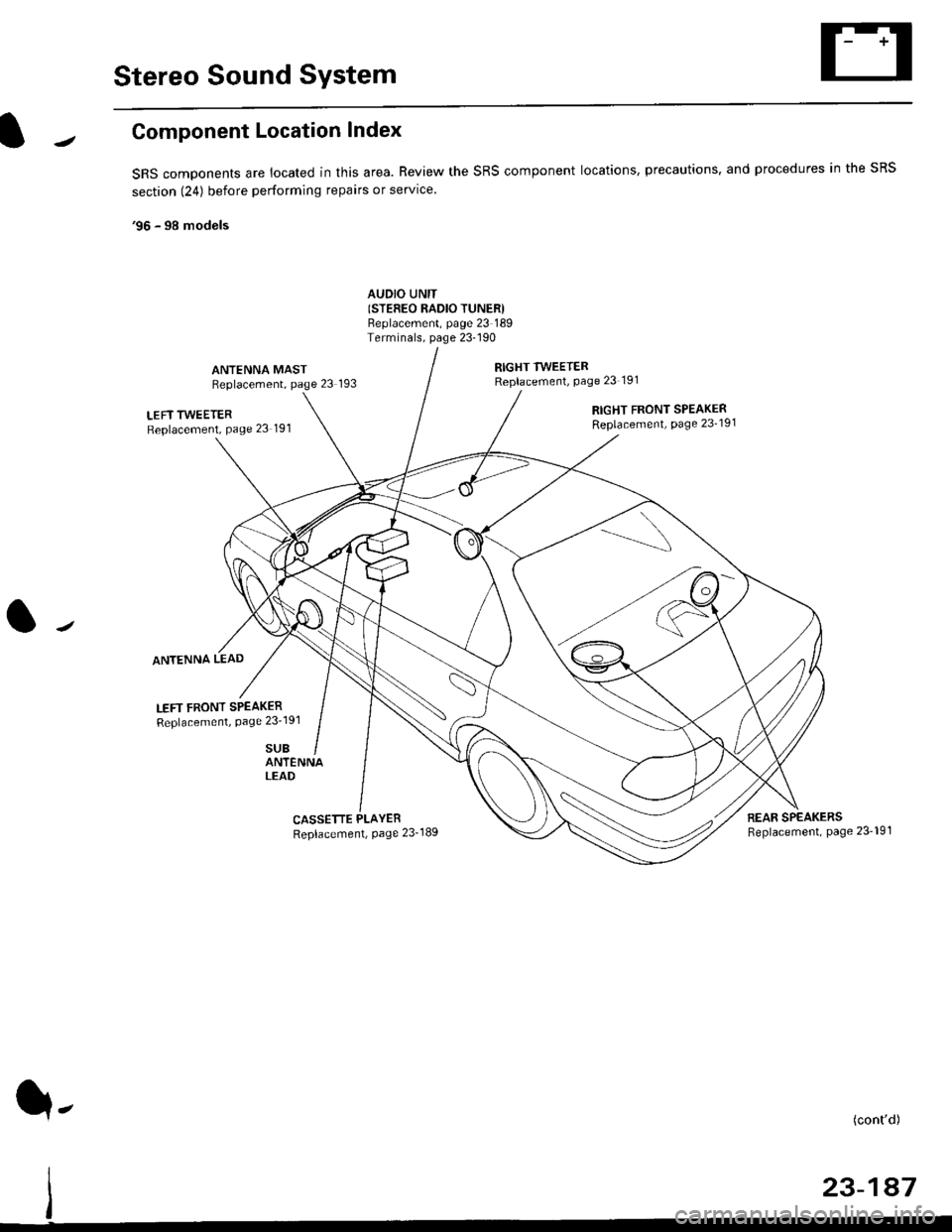
Stereo Sound System
Component Location Index
SRS components are located in this area. Review the SRS component locations, precautions. and procedures in the SRS
section (24) before performing repairs or service.
'96 - 98 models
AUDIO UNIT(STEFEO RADIO TUNERIBeplacement, page 23 189Terminals, page 23-190
ANTENNA MASTReplacement, page 23 193
RIGHT TWEETERReplacement, Page 23 191
LEFT TWEETERReplacement, Page 23 191
ANTENNA LEAD
LEFT FRONT SPEAKER
Replacement, Page 23'191
SUB
RIGHT FRONT SPEAKERReplacement, page 23'191
ANTENNALEAD
CASSETTE PLAYER
Replacement, Page 23-189REAR SPEAKERSReplacement, page 23- 19'l
(cont'd)
23-147
q-
Page 1659 of 2189
![HONDA CIVIC 1998 6.G Workshop Manual UNDER DASHFUSE/RELAY 80X
r*.i,,";l
I
I
I
I
I
I
IYEUFEDWHTiELU
Circuit Diagram (96 - 98 modelsl
A15A16
NoJ0 (7 sA)
v
IRED]BLK
RED
I
I
I
J
DASH LIGHTSBRIGHTNESSCONTROLLER
ANTENNALEAD
BRN/WHTBLK
G501
LE HONDA CIVIC 1998 6.G Workshop Manual UNDER DASHFUSE/RELAY 80X
r*.i,,";l
I
I
I
I
I
I
IYEUFEDWHTiELU
Circuit Diagram (96 - 98 modelsl
A15A16
NoJ0 (7 sA)
v
IRED]BLK
RED
I
I
I
J
DASH LIGHTSBRIGHTNESSCONTROLLER
ANTENNALEAD
BRN/WHTBLK
G501
LE](/manual-img/13/6068/w960_6068-1658.png)
UNDER DASHFUSE/RELAY 80X
r*.i,,";l
I
I
I
I
I
I
IYEUFEDWHTiELU
Circuit Diagram ('96 - 98 modelsl
A15A16
NoJ0 (7 sA)
v
IRED]BLK
RED
I
I
I
J
DASH LIGHTSBRIGHTNESSCONTROLLER
ANTENNALEAD
BRN/WHTBLK
G501
LEFT FHONTDOOF SPEAKER
I RED,^/Er
ILI�l
RIGHT REARSPEAKER
I BLU/YEL
III�t
SPEAKER
q-
IGN TION SWITCHUNDER.HOOD FUSE/FELAY BOX
AUDIO UN T(STEREO RAOLO TUNER)
@
LEFTRIGHTTWEETER
GRY]BLK
23-189
Page 1661 of 2189
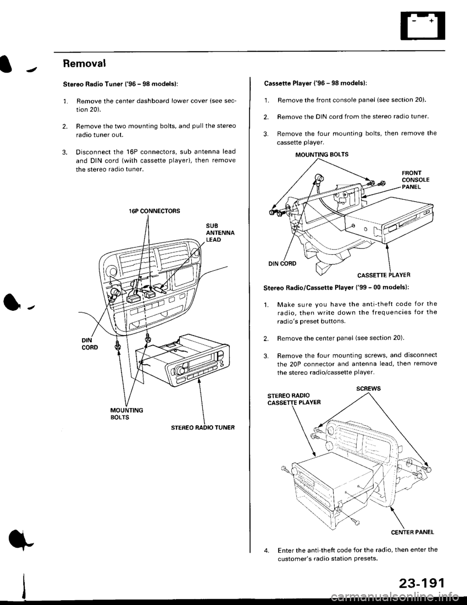
Removal
Stereo Radio Tuner ('96 - 98 modelsl:
3.
1.
2.
Remove the center dashboard lower cover (see sec-
tion 20).
Remove the two mounting bolts, and pullthe stereo
radao tuner out.
Disconnect the 16P connectors, sub antenna lead
and DIN cord (with cassette playerl, then remove
the stereo radio tuner.
16P CONNECTORS
1.
2.
Cassette Player ('96 - 98 modelsl:
Remove the front console panel (see section 20).
Remove the DIN cord from the stereo radio tuner.
Remove the four mounting bolts, then remove the
cassette player.
Stereo Radio/Cassette Player ('99 - 00 modelsl:
1. Make sure you have the anti-theft code for the
radio, then write down the frequencies for the
radio's oreset buttons.
Remove the center panel (see section 20).
Remove the four mounting screws, and disconnect
the 20P connector and antenna lead, then remove
the stereo radio/cassette player.
2.
3.
MOUNTING BOLTS
scREws
Enter the anti-theft code for the radio, then enter the
customer's radio station Presets.
23-191
Page 1662 of 2189
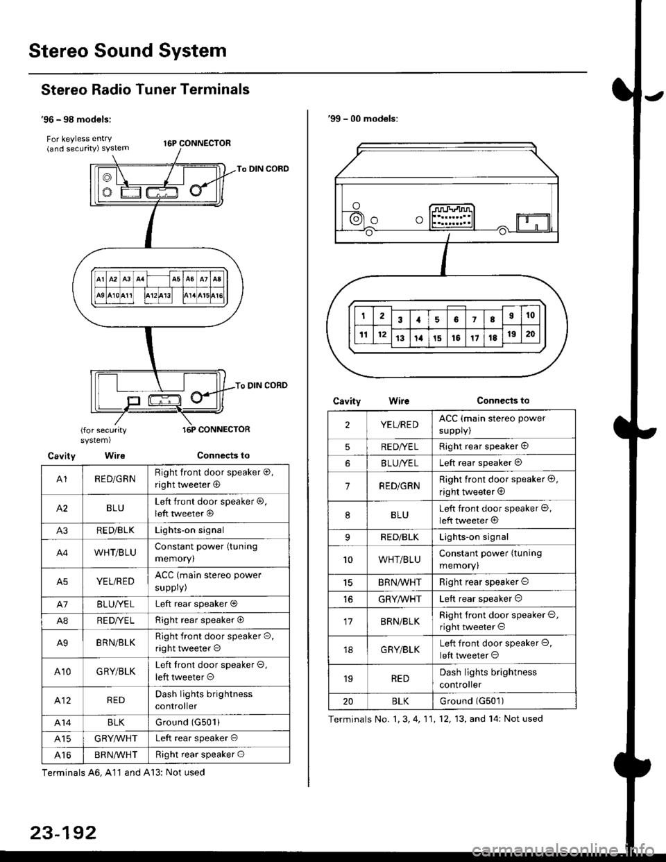
Stereo Sound System
Stereo Radio Tuner Terminals
'96 - 98 models:
For keyless entry . t6p coNNEcroR(and securrty) syslem
To DIN CORD
To DIN CORD
(for securitysystem)
Cavity Wire
A1RED/GRNRight front door speaker o,
right tweeter @
BLULeft front door speaker @,
left tweeter @
A3RE D/B LKLights-on signal
A4WHT/BLUConstant power (tuning
memoryl
A5YEL/REDACC (main stereo power
suppry)
A7BLUI/ELLeft rear speaker O
A8RE DI/E LRight rear speaker O
A9BRN/BLKRight front door speaker O,
right tweeter o
A10GRY/BLKLeft tront door speaker O,
left tweeter O
412REDDash lights brightness
controller
A14BLKGround (G501)
415GRYMHTLeft rear speaker O
Al6BR N/VVHTRight rear speaker O
Terminals A6, A11 and A13: Not used
23-192
'99 - 00 models:
CsvityConnccts toWire
2YEL/REDACC (main stereo power
suppry)
5RE DI/E LRight rear speaker @
BLUI/ELLeft rear speaker @
7RED/GRNRight front door speaker @,
right tweeter @
8BLULeft front door speaker @,
left tweeter @
9RED/BLKLights-on signal
10WHT/BLUConstant power (tuning
memory)
15BRN,ryVHTRight rear speaker O
GRYMHTLeft rear speaker O
17BRN/BLKRight front door speaker O,
right tweeter O
18G RY/BLKLeft front door speaker O,
left tweeter O
'19REDDash lights brightness
controller
20BLKurouno t(l5u t,
Terminals No. 1, 3, 4, 11,12, 13, and 14: Not used
Page 1721 of 2189
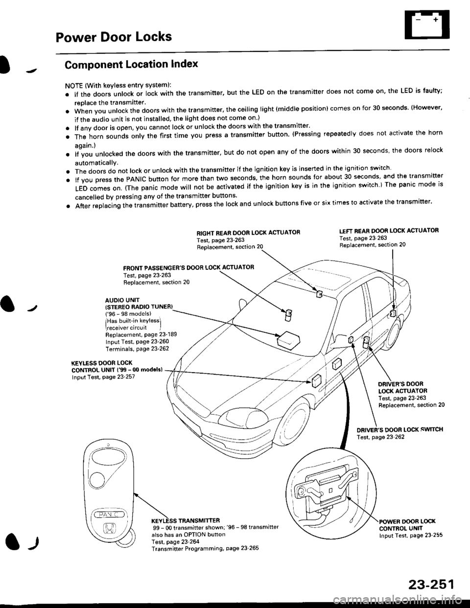
Power Door Locks
Component Location Index
NOTE (With keyless entry systeml:
. It the doors unlock or lock with the transmitter, but the LED on the transmitter does not come on, the LED is faulty;
replace the transmitter'
. when vou unlock the doors with the transmitter, the ceiling light (middle position) comes on for 30 seconds. (However,
if the audio unit is not installed, the light does not come on )
. lf any door is open, you cannot lock or unlockthe doors with the transmitter'
. The horn sounds only the first time you press a transmitter button. (Pressing repeatedly does not activate the horn
again.)
o lf vou unlocked the doors with the transmitter, but do not open any of the doors within 30 seconds, the doors relock
automatically.
. The doors do not lock or unlock with the transmitter if the ignition key is inserted in the ignition switch
. lf you press the PANIC button for more than two seconds, the horn sounds for about 30 seconds, and the transm'fer
LED comes on. (The panic mode will not be activated iJ the ignition key is in the ignition switch ) The panic mode is
cancelled by pressing any of the transmitter buttons'
o After replacing the transmitter battery, press the lock and unlock buttons five or six times to activate the transmitter'
Replacement, section 20
FRONT PASSENGER'S DOOR LOCK ACTUATOR
RIGHT REAR DOOR LOCK ACTUATOR
Test, page 23-263
I.IFT REAR DOOR LOCK ACTUATOR
Test, page 23 263Replacement, section 20
LOCK ACTUATORTest, page 23-263Replacement, section 20
ORIVER'S DOOR LOCK SWITCH
Test, page 23'262
DOOR L@XCONTROL UN]TInput Test, page 23 255
23-251
Test, page 23-263Replacement, section 20
AUDIO UNIT(STER€O RADIO TUNER)
{'96 - 98 models)
lHas built-in keylessl
eceiver circuit IReplacement, page 23-189
Input Test, page 23-260
Terminals, page 23-262
KEYLESS DOOR LOCKCONTROL UNIT l'99 - 00 modelsl
Input Test, Page 23-257
l-l
TRANSMITTER99 - 0O transmitter shown;'96 -98 transmifter
also has an OPTION buttonTest, page 23-264Transmitter Programming, page 23_265
Qi,,a/
/----
L(ru
i'.-8,-'l
/'-'6
Page 1737 of 2189
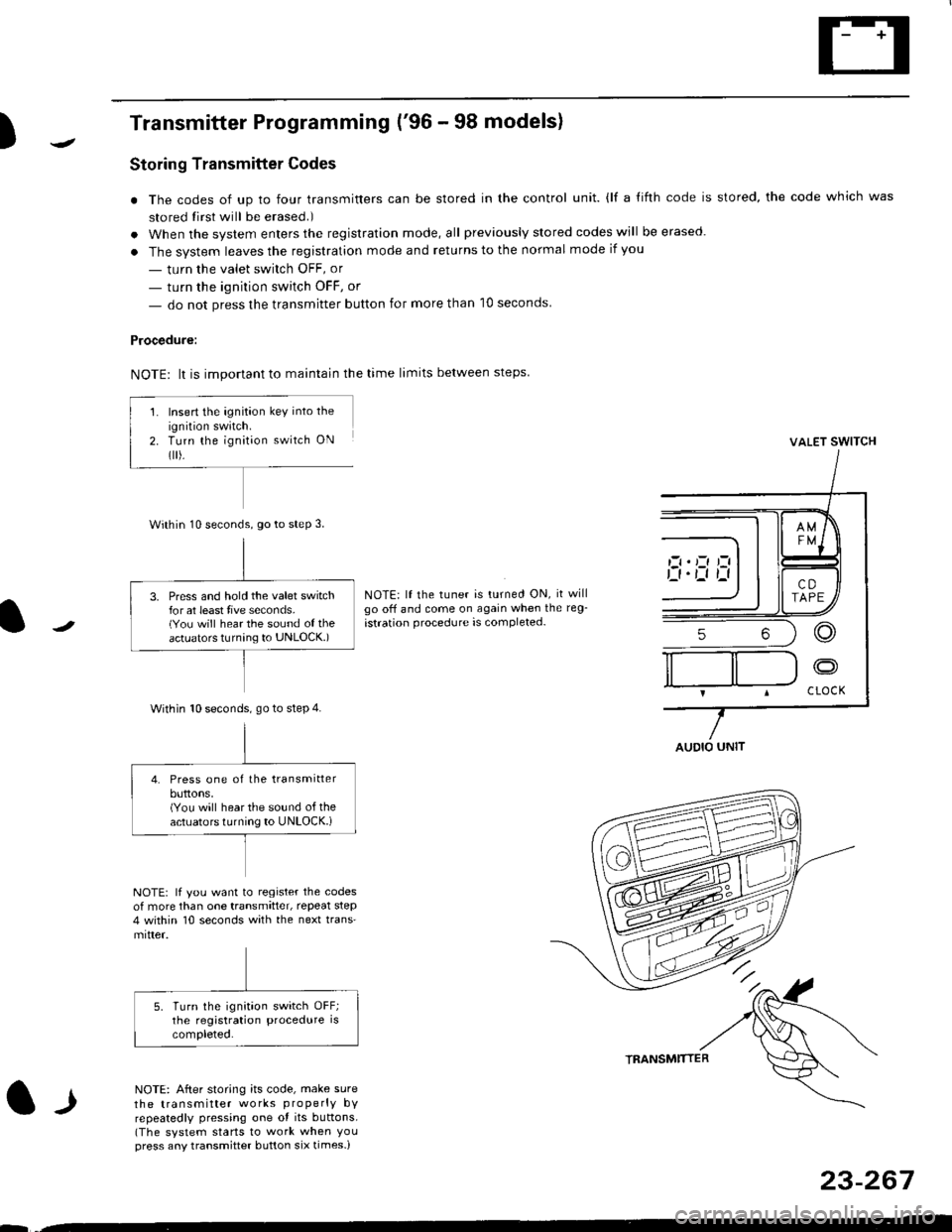
)
Transmitter Programming ('96 - 98 models)
Storing Transmitter Codes
. The codes of up to four transmitters can be stored in the control unit. {lf a {ifth code is stored, the code which was
stored tirst will be erased.)
. When the system enters the registration mode, all previously slored codes will be erased.
. The system leaves the registration mode and returns to the normal mode if you
- turn the valet swirch OFF, or
- turn the ignition switch OFF, or
- do not press the transmitter button for more than 10 seconds
Procedure:
NOTE: lt is important to maintain the time limits between steps
VALET SWITCH
NOTE: lf the tuner is turned ON, it willgo off and come on again when the reg-
istration procedure is completed-
l-l
NOTE: lf you want to register the codesof more than one transmitter, repeat step4 within 10 seconds with the next trans'mitter.
NOTE: After storing its code, make sure
the transmitter works properly bYrepeatedly pressing one ot its buttons.(The system starts to work when Youpress any transmitter button six times-)
TRANSMTITTER
23-267
--
Insert the ignition key into the
ignition swatch.Turn the ignit;on switch ON
flr).
Within 10 seconds, go to steP 3.
3. Press and hold the valet switchfor at least tive seconds.(You will hear the sound of theactuators turnang to UNLOCK.)
Within 10 seconds. go to step 4.
4. Press one of the transmitterbuttons,(You will hear the sound of theactuators turning to UNLOCK.i
AUDIO UNIT