1998 DODGE RAM 1500 ESP
[x] Cancel search: ESPPage 1451 of 2627

TIMING/CHAIN AND
SPROCKETS
REMOVAL
(1) Disconnect battery negative cable.
(2) Drain cooling system.
(3) Remove Timing Chain Cover.
CAUTION: The camshaft pin and the slot in the cam
sprocket must be clocked at 12:00. The crankshaft
keyway must be clocked at 2:00. The crankshaft
sprocket must be installed so that the dots and or
paint marking is at 6:00.
(4) Re-install the vibration damper bolt finger
tight. Using a suitable socket and breaker bar, rotate
the crankshaft to align timing chain sprockets and
keyways as shown (Fig. 33).
(5) Retract tensioner shoe until hole in shoe lines
up with hole in bracket. Slide a suitable pin into the
holes.
(6) Remove camshaft sprocket attaching bolt and
remove timing chain with crankshaft and camshaft
sprockets.
(7) If tensioner assembly is to be replaced, remove
the tensioner to block bolts and remove tensioner
assembly.
INSTALLATION
(1) If tensioner assembly is being replaced, install
tensioner and mounting bolts. Torque bolts to 28 N´m
(250 in. lbs.).
(2) Retract tensioner if required.
CAUTION: The camshaft pin and the slot in the cam
sprocket must be clocked at 12:00. The crankshaft
keyway must be clocked at 2:00. The crankshaft
sprocket must be installed so that the dots and or
paint marking is at 6:00.
(3) Place both camshaft sprocket and crankshaft
sprocket on the bench with timing marks on exact
imaginary center line through both camshaft and
crankshaft bores (Fig. 34).
CAUTION: The timing chain must be installed with
the single plated link aligned with the dot and or
paint marking on the camshaft sprocket. The crank-
shaft sprocket is aligned with the dot and or paint
marking on the sprocket between two plated timing
chain links.
(4) Place timing chain around both sprockets (Fig.
34).
(5) Lift sprockets and chain (keep sprockets tight
against the chain in position as shown).
(6) Slide both sprockets evenly over their respec-
tive shafts and check alignment of timing marks.
Fig. 33 5.7L TIMING MARK ALIGNMENT
1 - Chain Tensioner
2 - Camshaft Sprocket
3 - Crankshaft Sprocket
Fig. 34 5.7L TIMING MARK ALIGNMENT
1 - Chain Tensioner
2 - Camshaft Sprocket
3 - Crankshaft Sprocket
9 - 228 ENGINE - 5.7LDR
Page 1505 of 2627

NOTE: If cylinders have ridges, the cylinders are
oversize and will more than likely need boring.
(8) Using a hammer and steel stamp, stamp the
cylinder number in the top of each piston. The front
of the piston is identified by a stamping on the top of
the piston. DO NOT stamp in the outside 5 mm (.197
in.) of the piston diameter. DO NOT stamp over the
piston pin.
(9) Mark the connecting rod and cap with the cor-
responding cylinder numbers.
(10) Remove the connecting rod bolts and rod caps.
Use care so the cylinder bores and connecting rods
are not damaged.
(11) Use a hammer handle or similar object to
push the piston and connecting rod through the cyl-
inder bore.
(12) Store the piston/rod assemblies in a rack.
CLEANINGÐPISTON AND CONNECTING ROD
CAUTION: DO NOT use bead blast to clean the pis-
tons. DO NOT clean the pistons and rods in an acid
tank.
PISTON
Clean the pistons and pins in a suitable solvent,
rinse in hot water and blow dry with compressed air.
Soaking the pistons over night will loosen most of the
carbon build up. De-carbon the ring grooves with a
broken piston ring and again clean the pistons in sol-
vent. Rinse in hot water and blow dry with com-
pressed air.
CONNECTING ROD
Clean the connecting rods in a suitable solvent,
rinse in hot water and blow dry with compressed air.
INSPECTION
INSPECTION - PISTONS
Inspect the pistons for damage and excessive wear.
Check top of the piston, ring grooves, skirt and pin
bore. Measure the piston skirt diameter. If the piston
is out of limits, replace the piston.
PISTON SKIRT DIAMETER (MIN.)
101.775 mm (4.006 in. )The upper groove only needs to be inspected for
damage. Use a new piston ring to measure the clear-
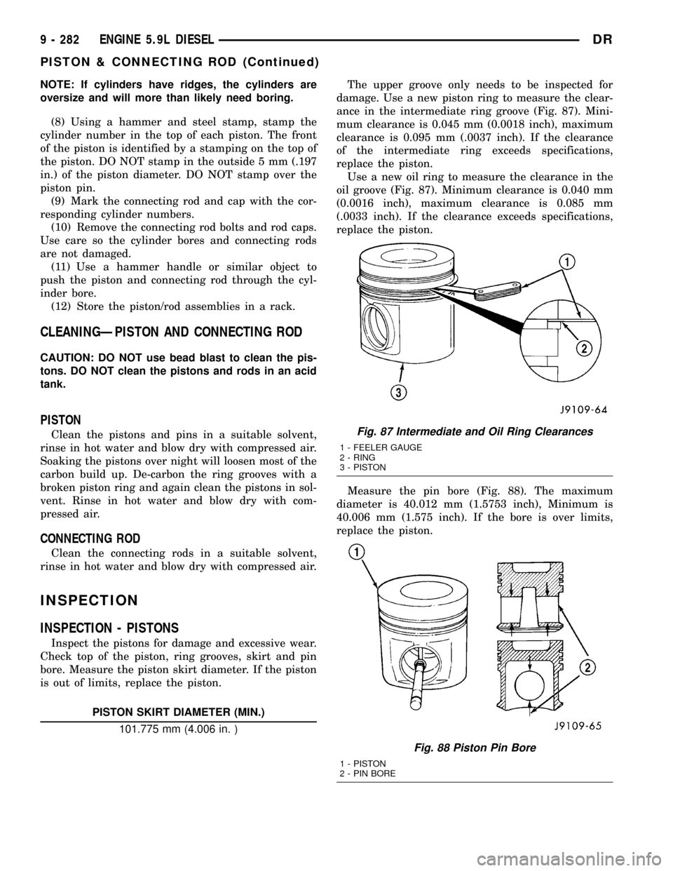
ance in the intermediate ring groove (Fig. 87). Mini-
mum clearance is 0.045 mm (0.0018 inch), maximum
clearance is 0.095 mm (.0037 inch). If the clearance
of the intermediate ring exceeds specifications,
replace the piston.
Use a new oil ring to measure the clearance in the
oil groove (Fig. 87). Minimum clearance is 0.040 mm
(0.0016 inch), maximum clearance is 0.085 mm
(.0033 inch). If the clearance exceeds specifications,
replace the piston.
Measure the pin bore (Fig. 88). The maximum
diameter is 40.012 mm (1.5753 inch), Minimum is
40.006 mm (1.575 inch). If the bore is over limits,
replace the piston.
Fig. 87 Intermediate and Oil Ring Clearances
1 - FEELER GAUGE
2 - RING
3 - PISTON
Fig. 88 Piston Pin Bore
1 - PISTON
2 - PIN BORE
9 - 282 ENGINE 5.9L DIESELDR
PISTON & CONNECTING ROD (Continued)
Page 1596 of 2627

stream. The spraying action atomizes the fuel, add-
ing it to the air entering the combustion chamber.
The nozzle (outlet) ends of the injectors are posi-
tioned into openings in the intake manifold just
above the intake valve ports of the cylinder head.
The engine wiring harness connector for each fuel
injector is equipped with an attached numerical tag
(INJ 1, INJ 2 etc.). This is used to identify each fuel
injector.
The injectors are energized individually in a
sequential order by the Powertrain Control Module
(PCM). The PCM will adjust injector pulse width by
switching the ground path to each individual injector
on and off. Injector pulse width is the period of time
that the injector is energized. The PCM will adjust
injector pulse width based on various inputs it
receives.
Battery voltage is supplied to the injectors through
the ASD relay.
The PCM determines injector pulse width based on
various inputs.
OPERATION - PCM OUTPUT
The nozzle ends of the injectors are positioned into
openings in the intake manifold just above the intake
valve ports of the cylinder head. The engine wiring
harness connector for each fuel injector is equipped
with an attached numerical tag (INJ 1, INJ 2 etc.).
This is used to identify each fuel injector with its
respective cylinder number.
The injectors are energized individually in a
sequential order by the Powertrain Control Module
(PCM). The PCM will adjust injector pulse width by
switching the ground path to each individual injector
on and off. Injector pulse width is the period of time
that the injector is energized. The PCM will adjust
injector pulse width based on various inputs it
receives.
Battery voltage (12 volts +) is supplied to the injec-
tors through the ASD relay. The ASD relay will shut-
down the 12 volt power source to the fuel injectors if
the PCM senses the ignition is on, but the engine is
not running. This occurs after the engine has not
been running for approximately 1.8 seconds.
The PCM determines injector on-time (pulse width)
based on various inputs.
REMOVAL
(1) Remove fuel rail. Refer to Fuel Injector Rail
Removal.
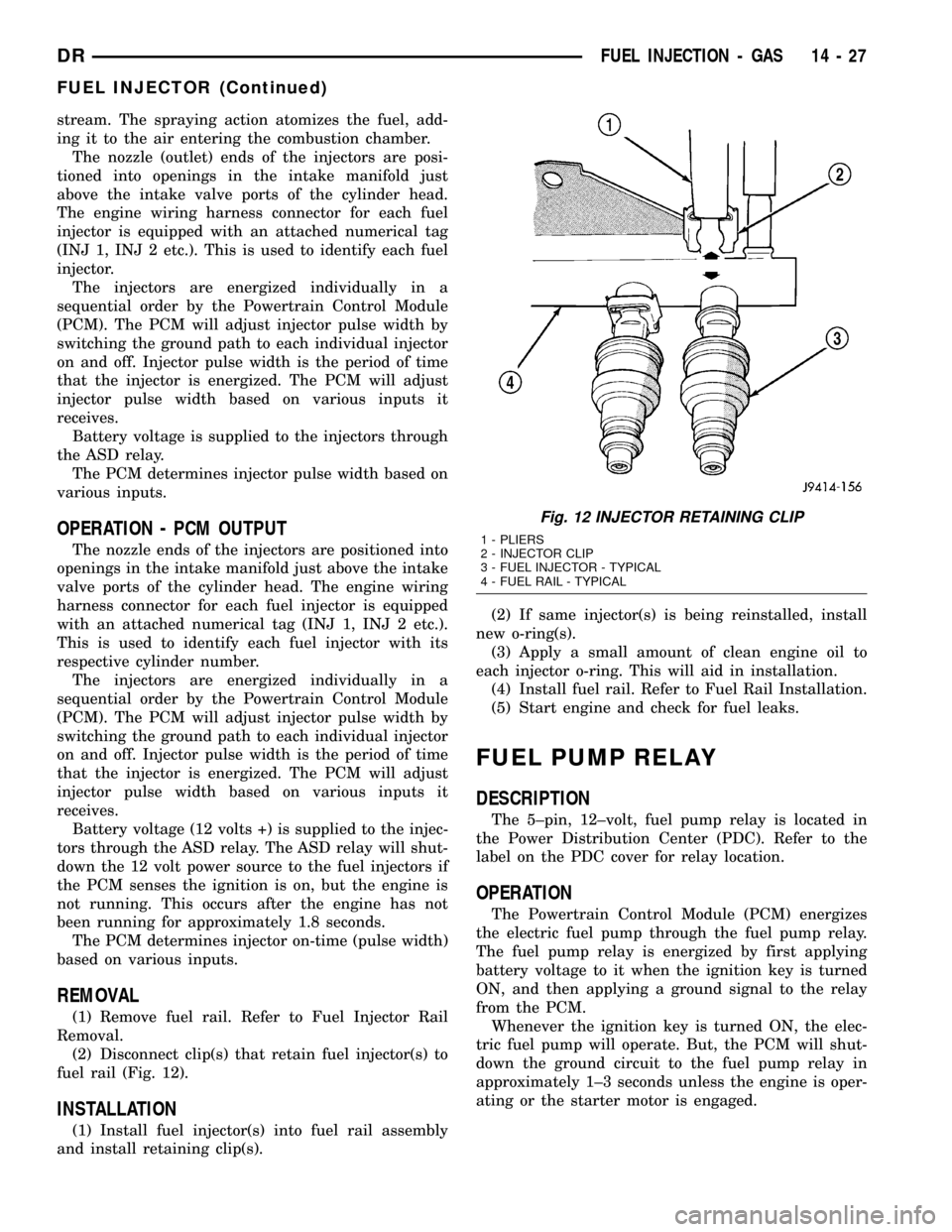
(2) Disconnect clip(s) that retain fuel injector(s) to
fuel rail (Fig. 12).
INSTALLATION
(1) Install fuel injector(s) into fuel rail assembly
and install retaining clip(s).(2) If same injector(s) is being reinstalled, install
new o-ring(s).
(3) Apply a small amount of clean engine oil to
each injector o-ring. This will aid in installation.
(4) Install fuel rail. Refer to Fuel Rail Installation.
(5) Start engine and check for fuel leaks.
FUEL PUMP RELAY
DESCRIPTION
The 5±pin, 12±volt, fuel pump relay is located in
the Power Distribution Center (PDC). Refer to the
label on the PDC cover for relay location.
OPERATION
The Powertrain Control Module (PCM) energizes
the electric fuel pump through the fuel pump relay.
The fuel pump relay is energized by first applying
battery voltage to it when the ignition key is turned
ON, and then applying a ground signal to the relay
from the PCM.
Whenever the ignition key is turned ON, the elec-
tric fuel pump will operate. But, the PCM will shut-
down the ground circuit to the fuel pump relay in
approximately 1±3 seconds unless the engine is oper-
ating or the starter motor is engaged.
Fig. 12 INJECTOR RETAINING CLIP
1 - PLIERS
2 - INJECTOR CLIP
3 - FUEL INJECTOR - TYPICAL
4 - FUEL RAIL - TYPICAL
DRFUEL INJECTION - GAS 14 - 27
FUEL INJECTOR (Continued)
Page 1602 of 2627

²Engine load
²Injector pulse-width
²Spark-advance programs
²Shift-point strategies (certain automatic trans-
missions only)
²Idle speed
²Decel fuel shutoff
The MAP sensor signal is provided from a single
piezoresistive element located in the center of a dia-
phragm. The element and diaphragm are both made
of silicone. As manifold pressure changes, the dia-
phragm moves causing the element to deflect, which
stresses the silicone. When silicone is exposed to
stress, its resistance changes. As manifold vacuum
increases, the MAP sensor input voltage decreases
proportionally. The sensor also contains electronics
that condition the signal and provide temperature
compensation.
The PCM recognizes a decrease in manifold pres-
sure by monitoring a decrease in voltage from the
reading stored in the barometric pressure memory
cell. The MAP sensor is a linear sensor; meaning as
pressure changes, voltage changes proportionately.
The range of voltage output from the sensor is usu-
ally between 4.6 volts at sea level to as low as 0.3
volts at 26 in. of Hg. Barometric pressure is the pres-
sure exerted by the atmosphere upon an object. At
sea level on a standard day, no storm, barometric
pressure is approximately 29.92 in Hg. For every 100
feet of altitude, barometric pressure drops 0.10 in.
Hg. If a storm goes through, it can change baromet-
ric pressure from what should be present for that
altitude. You should know what the average pressure
and corresponding barometric pressure is for your
area.
REMOVAL
3.7L V-6
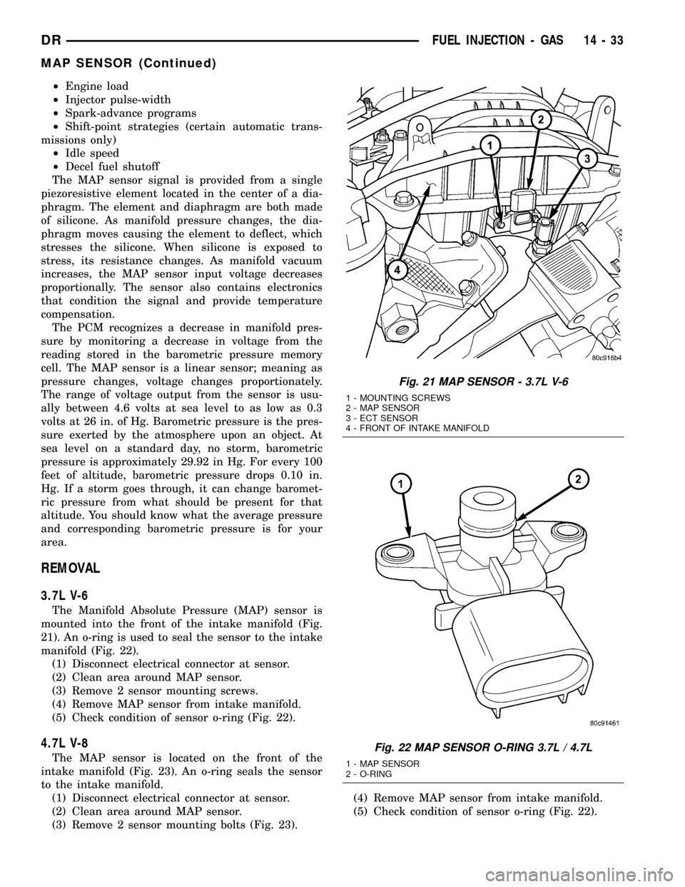
The Manifold Absolute Pressure (MAP) sensor is
mounted into the front of the intake manifold (Fig.
21). An o-ring is used to seal the sensor to the intake
manifold (Fig. 22).
(1) Disconnect electrical connector at sensor.
(2) Clean area around MAP sensor.
(3) Remove 2 sensor mounting screws.
(4) Remove MAP sensor from intake manifold.
(5) Check condition of sensor o-ring (Fig. 22).
4.7L V-8
The MAP sensor is located on the front of the
intake manifold (Fig. 23). An o-ring seals the sensor
to the intake manifold.
(1) Disconnect electrical connector at sensor.
(2) Clean area around MAP sensor.
(3) Remove 2 sensor mounting bolts (Fig. 23).(4) Remove MAP sensor from intake manifold.
(5) Check condition of sensor o-ring (Fig. 22).
Fig. 21 MAP SENSOR - 3.7L V-6
1 - MOUNTING SCREWS
2 - MAP SENSOR
3 - ECT SENSOR
4 - FRONT OF INTAKE MANIFOLD
Fig. 22 MAP SENSOR O-RING 3.7L / 4.7L
1 - MAP SENSOR
2 - O-RING
DRFUEL INJECTION - GAS 14 - 33
MAP SENSOR (Continued)
Page 1610 of 2627

(11) Install air resonator tube to throttle body.
(12) Before starting engine, operate accelerator
pedal to check for any binding.
5.7L V-8
(1) Attach cable to Accelerator Pedal Position Sen-
sor (APPS). Refer to APPS Removal / Installation.
(2) Push cable housing into rubber grommet and
through opening in dash panel.
(3) From inside vehicle, install clip holding cable
to dashpanel (Fig. 1).
(4) From inside vehicle, slide throttle cable core
wire into opening in top of pedal arm.
(5) Push cable retainer (clip) into pedal arm open-
ing until it snaps in place.
(6) Before starting engine, operate accelerator
pedal to check for any binding.
(7) If necessary, use DRB IIItScan Tool to erase
any APPS Diagnostic Trouble Codes (DTC's) from
PCM.
THROTTLE POSITION SENSOR
DESCRIPTION
The 3-wire Throttle Position Sensor (TPS) is
mounted on the throttle body and is connected to the
throttle blade shaft.
The 5.7L V-8 engine does not use a separate TPS
on the throttle body.
OPERATION
The 5.7L V-8 engine does not use a separate Throt-
tle Position Sensor (TPS) on the throttle body.
The 3±wire TPS provides the Powertrain Control
Module (PCM) with an input signal (voltage) that
represents the throttle blade position of the throttle
body. The sensor is connected to the throttle blade
shaft. As the position of the throttle blade changes,
the output voltage of the TPS changes.
The PCM supplies approximately 5 volts to the
TPS. The TPS output voltage (input signal to the
PCM) represents the throttle blade position. The
PCM receives an input signal voltage from the TPS.
This will vary in an approximate range of from .26
volts at minimum throttle opening (idle), to 4.49 volts
at wide open throttle. Along with inputs from other
sensors, the PCM uses the TPS input to determine
current engine operating conditions. In response to
engine operating conditions, the PCM will adjust fuel
injector pulse width and ignition timing.The PCM needs to identify the actions and position
of the throttle blade at all times. This information is
needed to assist in performing the following calcula-
tions:
²Ignition timing advance
²Fuel injection pulse-width
²Idle (learned value or minimum TPS)
²Off-idle (0.06 volt)
²Wide Open Throttle (WOT) open loop (2.608
volts above learned idle voltage)
²Deceleration fuel lean out
²Fuel cutoff during cranking at WOT (2.608 volts
above learned idle voltage)
²A/C WOT cutoff (certain automatic transmis-
sions only)
REMOVAL
3.7L V6
The Throttle Position Sensor (TPS) is mounted to
the throttle body (Fig. 37), or (Fig. 38).
(1) Remove air resonator tube at throttle body.
(2) Disconnect TPS electrical connector.
(3) Remove 2 TPS mounting screws.
(4) Remove TPS.
Fig. 37 TPS LOCATION - 3.7L V-6
1 - THROTTLE POSITION SENSOR (TPS)
2 - MOUNTING SCREWS
3 - IDLE AIR CONTROL MOTOR (IAC)
4 - MOUNTING SCREWS
DRFUEL INJECTION - GAS 14 - 41
THROTTLE CONTROL CABLE (Continued)
Page 1616 of 2627

STANDARD PROCEDURE
STANDARD PROCEDURES - WATER DRAINING
AT FUEL FILTER
Refer to Fuel Filter/Water Separator removal/in-
stallation for procedures.
STANDARD PROCEDURES - CLEANING FUEL
SYSTEM PARTS
CAUTION: Cleanliness cannot be overemphasized
when handling or replacing diesel fuel system com-
ponents. This especially includes the fuel injectors,
high-pressure fuel lines and fuel injection pump.
Very tight tolerances are used with these parts. Dirt
contamination could cause rapid part wear and pos-
sible plugging of fuel injector nozzle tip holes. This
in turn could lead to possible engine misfire.
Always wash/clean any fuel system component
thoroughly before disassembly and then air dry.
Cap or cover any open part after disassembly.
Before assembly, examine each part for dirt, grease
or other contaminants and clean if necessary. When
installing new parts, lubricate them with clean
engine oil or clean diesel fuel only.
STANDARD PROCEDURE - FUEL SYSTEM
PRIMING
A certain amount of air becomes trapped in the
fuel system when fuel system components on the
supply and/or high-pressure side are serviced or
replaced. Fuel system priming is accomplished using
the electric fuel transfer (lift) pump.
Servicing or replacing fuel system components will
not require fuel system priming.
The fuel transfer (lift) pump is self-priming: When
the key is first turned on (without cranking engine),
the pump operates for approximately 1 to 2 second
and then shuts off. The pump will also operate for up
to 25 seconds after the starter is quickly engaged,
and then disengaged without allowing the engine to
start. The pump shuts off immediately if the key is
on and the engine stops running.
(1) Turn key to CRANK position and quickly
release key to ON position before engine starts. This
will operate fuel transfer pump for approximately 25
seconds.
(2) Crank engine. If the engine does not start after
25 seconds, turn key OFF. Repeat previous step until
engine starts.
(3) Fuel system priming is now completed.
(4) Attempt to start engine. If engine will not
start, proceed to following steps.When engine does
start, it may run erratically and be noisy for a
few minutes. This is a normal condition.
CAUTION: Do not engage the starter motor for more
than 30 seconds at a time. Allow two minutes
between cranking intervals.
(5) Perform previous fuel priming procedure steps
using fuel transfer pump. Be sure fuel is present at
fuel tank.
(6) Crank the engine for 30 seconds at a time to
allow fuel system to prime.
WARNING: THE FUEL INJECTION PUMP SUPPLIES
EXTREMELY HIGH FUEL PRESSURE TO EACH INDI-
VIDUAL INJECTOR THROUGH THE HIGH-PRES-
SURE LINES. FUEL UNDER THIS AMOUNT OF
PRESSURE CAN PENETRATE THE SKIN AND
CAUSE PERSONAL INJURY. WEAR SAFETY GOG-
GLES AND ADEQUATE PROTECTIVE CLOTHING.
DO NOT LOOSEN FUEL FITTINGS WHILE ENGINE
IS RUNNING.
WARNING: ENGINE MAY START WHILE CRANKING
STARTER MOTOR.
Fig. 2 FUEL INJECTORS
1 - SOLENOID CONNECTIONS
2 - ROCKER HOUSING
3 - FUEL INJECTOR
4 - PASSTHROUGH CONNECTOR
DRFUEL DELIVERY - DIESEL 14 - 47
FUEL DELIVERY - DIESEL (Continued)
Page 1623 of 2627

REMOVAL
CAUTION: Cleanliness cannot be overemphasized
when handling or replacing diesel fuel system com-
ponents. This especially includes the fuel injectors,
high-pressure fuel lines and fuel injection pump.
Very tight tolerances are used with these parts. Dirt
contamination could cause rapid part wear and pos-
sible plugging of fuel injector nozzle tip holes. This
in turn could lead to possible engine misfire.
Always wash/clean any fuel system component
thoroughly before disassembly and then air dry.
Cap or cover any open part after disassembly.
Before assembly, examine each part for dirt, grease
or other contaminants and clean if necessary. When
installing new parts, lubricate them with clean
engine oil or clean diesel fuel only.
(1) Disconnect both negative battery cables at both
batteries. Cover and isolate ends of both cables.
(2) Remove intake manifold air intake tube (above
injection pump) and its rubber connector hose (Fig.
7).
(3) Remove accessory drive belt.
(4) Thoroughly clean the rear of injection pump,
and attachment points for its 3 fuel lines (Fig. 8).
Also clean the opposite ends of these same 3 lines at
their attachment points.
(5) Disconnect Fuel Control Actuator (FCA) electri-
cal connector at rear of injection pump (Fig. 9).
CAUTION: Whenever a fuel line fitting is connected
to a secondary fitting, always use a back-up wrench
on the secondary fitting. Do not allow the second-
ary fitting to rotate.
(6) Remove fuel line (injection pump-to-fuel pres-
sure limiting valve).
(7) Remove fuel line (injection pump-to-fuel rail).
Use back-up wrench on fitting at fuel pump.
(8) Remove fuel line (injection pump-to-fuel filter
housing).
(9) Remove fuel pump drive gear access cover
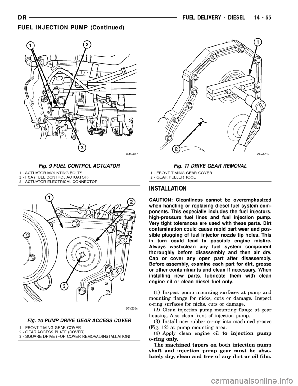
(plate) with a 3/8º drive ratchet. Plate is threaded to
timing gear cover (Fig. 10).
(10) Remove fuel pump drive gear mounting nut
and washer.
(11) Attach C3428B, or L4407A (or equivalent)
gear puller (Fig. 11) to pump drive gear with 2 bolts,
and separate gear from pump (a keyway is not used
on this particular injection pump). Leave drive gear
hanging loose within timing gear cover.
(12) Remove 3 injection pump mounting nuts (Fig.
12), and remove pump from engine.
Fig. 7 INTAKE TUBE AND CONNECTING HOSE
1 - MANIFOLD ABOVE HEATERS
2 - RUBBER CONNECTING HOSE
3 - METAL INTAKE TUBE
4 - CLAMPS (2)
Fig. 8 OVERFLOW VALVE
1 - BANJO BOLTS
2 - PUMP MOUNTING NUTS (3)
3 - FUEL INJECTION PUMP
4 - CASCADE OVERFLOW VALVE
14 - 54 FUEL DELIVERY - DIESELDR
FUEL INJECTION PUMP (Continued)
Page 1624 of 2627

INSTALLATION
CAUTION: Cleanliness cannot be overemphasized
when handling or replacing diesel fuel system com-
ponents. This especially includes the fuel injectors,
high-pressure fuel lines and fuel injection pump.
Very tight tolerances are used with these parts. Dirt
contamination could cause rapid part wear and pos-
sible plugging of fuel injector nozzle tip holes. This
in turn could lead to possible engine misfire.
Always wash/clean any fuel system component
thoroughly before disassembly and then air dry.
Cap or cover any open part after disassembly.
Before assembly, examine each part for dirt, grease
or other contaminants and clean if necessary. When
installing new parts, lubricate them with clean
engine oil or clean diesel fuel only.
(1) Inspect pump mounting surfaces at pump and
mounting flange for nicks, cuts or damage. Inspect
o-ring surfaces for nicks, cuts or damage.
(2) Clean injection pump mounting flange at gear
housing. Also clean front of injection pump.
(3) Install new rubber o-ring into machined groove
(Fig. 12) at pump mounting area.
(4) Apply clean engine oilto injection pump
o-ring only.
The machined tapers on both injection pump
shaft and injection pump gear must be abso-
lutely dry, clean and free of any dirt or oil film.
Fig. 9 FUEL CONTROL ACTUATOR
1 - ACTUATOR MOUNTING BOLTS
2 - FCA (FUEL CONTROL ACTUATOR)
3 - ACTUATOR ELECTRICAL CONNECTOR
Fig. 10 PUMP DRIVE GEAR ACCESS COVER
1 - FRONT TIMING GEAR COVER
2 - GEAR ACCESS PLATE (COVER)
3 - SQUARE DRIVE (FOR COVER REMOVAL/INSTALLATION)
Fig. 11 DRIVE GEAR REMOVAL
1 - FRONT TIMING GEAR COVER
2 - GEAR PULLER TOOL
DRFUEL DELIVERY - DIESEL 14 - 55
FUEL INJECTION PUMP (Continued)