1998 DODGE RAM 1500 timing belt
[x] Cancel search: timing beltPage 1435 of 2627
(5) Piston installation into the cylinder bore
requires slightly more pressure than that required
for non-coated pistons. The bonded coating on the
piston will give the appearance of a line-to-line fit
with the cylinder bore.
REMOVAL
(1) Disconnect negative cable from battery.
(2) Remove the following components:
²Oil pan and gasket/windage tray (Refer to 9 -
ENGINE/LUBRICATION/OIL PAN - REMOVAL).
²Cylinder head covers (Refer to 9 - ENGINE/
CYLINDER HEAD/CYLINDER HEAD COVER(S) -
REMOVAL) and (Refer to 9 - ENGINE/CYLINDER
HEAD/CYLINDER HEAD COVER(S) - REMOVAL).
²Timing chain cover (Refer to 9 - ENGINE/
VALVE TIMING/TIMING BELT / CHAIN COVER(S)
- REMOVAL).
²Cylinder head(s) (Refer to 9 - ENGINE/CYLIN-
DER HEAD - REMOVAL) and (Refer to 9 - ENGINE/
CYLINDER HEAD - REMOVAL).
(3) If necessary, remove top ridge of cylinder bores
with a reliable ridge reamer before removing pistons
from cylinder block.Be sure to keep tops of pis-
tons covered during this operation.Pistons and
connecting rods must be removed from top of cylinder
block. When removing piston and connecting rod
assemblies from the engine, rotate crankshaft so the
each connecting rod is centered in cylinder bore.CAUTION: DO NOT use a number stamp or a punch
to mark connecting rods or caps, as damage to
connecting rods could occur
NOTE: Connecting rods and bearing caps are not
interchangeable and should be marked before
removing to ensure correct reassembly.
(4)
Mark connecting rod and bearing cap positions
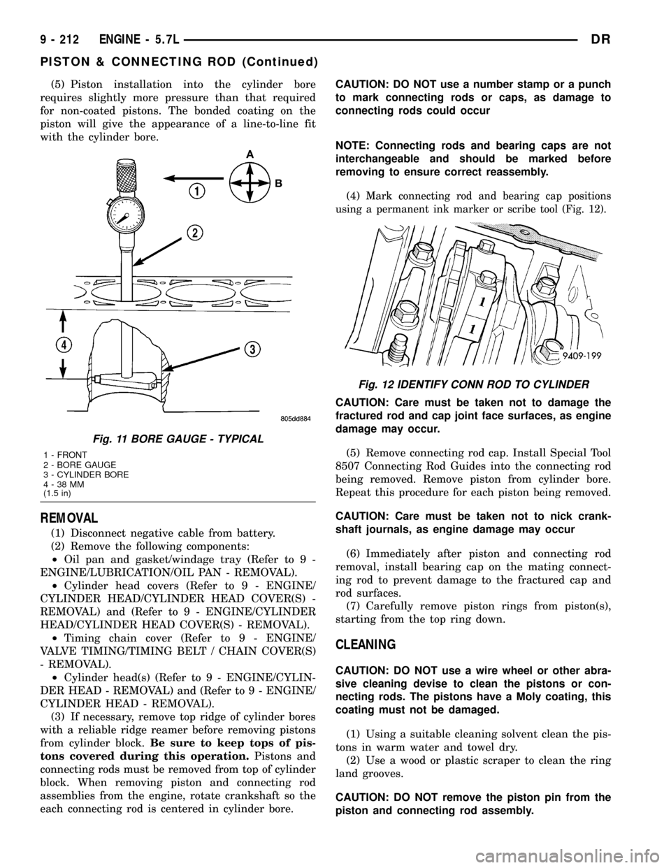
using a permanent ink marker or scribe tool (Fig. 12).
CAUTION: Care must be taken not to damage the
fractured rod and cap joint face surfaces, as engine
damage may occur.
(5) Remove connecting rod cap. Install Special Tool
8507 Connecting Rod Guides into the connecting rod
being removed. Remove piston from cylinder bore.
Repeat this procedure for each piston being removed.
CAUTION: Care must be taken not to nick crank-
shaft journals, as engine damage may occur
(6) Immediately after piston and connecting rod
removal, install bearing cap on the mating connect-
ing rod to prevent damage to the fractured cap and
rod surfaces.
(7) Carefully remove piston rings from piston(s),
starting from the top ring down.
CLEANING
CAUTION: DO NOT use a wire wheel or other abra-
sive cleaning devise to clean the pistons or con-
necting rods. The pistons have a Moly coating, this
coating must not be damaged.
(1) Using a suitable cleaning solvent clean the pis-
tons in warm water and towel dry.
(2) Use a wood or plastic scraper to clean the ring
land grooves.
CAUTION: DO NOT remove the piston pin from the
piston and connecting rod assembly.
Fig. 11 BORE GAUGE - TYPICAL
1 - FRONT
2 - BORE GAUGE
3 - CYLINDER BORE
4-38MM
(1.5 in)
Fig. 12 IDENTIFY CONN ROD TO CYLINDER
9 - 212 ENGINE - 5.7LDR
PISTON & CONNECTING ROD (Continued)
Page 1447 of 2627
OIL PAN
REMOVAL
(1) Disconnect the negative battery cable.
(2) Install engine support fixture special tool #
8534.Do not raise engine at this time.
(3) Loosen both left and right side engine mount
through bolts. Do not remove bolts.
(4) Remove the structural dust cover, if equipped.
(5) Drain engine oil.
(6) Remove the front crossmember(Refer to 13 -
FRAME & BUMPERS/FRAME/FRONT CROSS-
MEMBER - REMOVAL).
CAUTION: Only raise the engine enough to provide
clearance for oil pan removal. Check for proper
clearance at fan shroud to fan and cowl to intake
manifold.
(7) Raise engine using special tool # 8534 to pro-
vide clearance to remove oil pan.
NOTE: Do not pry on oil pan or oil pan gasket. Gas-
ket is integral to engine windage tray and does not
come out with oil pan.
(8) Remove the oil pan mounting bolts and oil pan.
NOTE: The double ended oil pan studs must be
installed in the same location that they were
removed from.
(9) Unbolt oil pump pickup tube and remove tube.
(10) Inspect the integral windage tray and gasket
and replace as needed.
INSTALLATION
(1) Clean the oil pan gasket mating surface of the
block and oil pan.
(2) Inspect the integral windage tray and gasket
and replace as needed.
(3) Reinstall the oil pump pickup tube with new
o-ring. Tighten tube to pump fasteners to 28 N´m
(250 in. lbs.).
NOTE: The double ended oil pan studs must be
installed in the same location that they were
removed from.
(4) Position the oil pan and install the mounting
bolts and studs.. Tighten the mounting bolts to 12
N´m (105 in.lbs.).
(5) Lower the engine into mounts using special
tool # 8534.
(6) Install both the left and right side engine
mount through bolts. Tighten the nuts to 68 N´m (50
ft. lbs.).(7) Remove special tool # 8534.
(8) Install structural dust cover, if equipped.
(9) Install the front crossmember(Refer to 13 -
FRAME & BUMPERS/FRAME/FRONT CROSS-
MEMBER - INSTALLATION).
(10) Fill engine oil.
(11) Reconnect the negative battery cable.
(12) Start engine and check for leaks.
OIL PUMP
REMOVAL
(1) Remove the oil pan and pick-up tube(Refer to 9
- ENGINE/LUBRICATION/OIL PAN - REMOVAL).
(2) Remove the timing chain cover(Refer to 9 -
ENGINE/VALVE TIMING/TIMING BELT / CHAIN
COVER(S) - REMOVAL).
(3) Remove the four bolts, and the oil pump.
CLEANING
(1) Wash all parts in a suitable solvent.
INSPECTION
CAUTION: Oil pump pressure relief valve and
spring should not be removed from the oil pump. If
these components are disassembled and or
removed from the pump the entire oil pump assem-
bly must be replaced.
(1) Remove the pump cover.
(2) Clean all parts thoroughly. Mating surface of
the oil pump housing should be smooth. If the pump
cover is scratched or grooved the oil pump assembly
should be replaced.
(3) Slide outer rotor into the body of the oil pump.
Press the outer rotor to one side of the oil pump body
and measure clearance between the outer rotor and
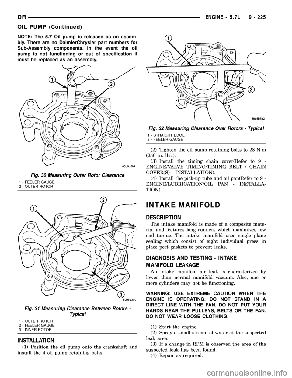
the body (Fig. 30). If the measurement is 0.235mm
(0.009 in.) or more the oil pump assembly must be
replaced.
(4) Install the inner rotor in the into the oil pump
body. Measure the clearance between the inner and
outer rotors (Fig. 31). If the clearance between the
rotors is .150 mm (0.006 in.) or more the oil pump
assembly must be replaced.
(5) Place a straight edge across the body of the oil
pump (between the bolt holes), if a feeler gauge of
.095 mm (0.0038 in.) or greater can be inserted
between the straightedge and the rotors, the pump
must be replaced (Fig. 32).
(6) Reinstall the pump cover. Torque fasteners to
15 N´m (132 in. lbs.).
9 - 224 ENGINE - 5.7LDR
Page 1448 of 2627
NOTE: The 5.7 Oil pump is released as an assem-
bly. There are no DaimlerChrysler part numbers for
Sub-Assembly components. In the event the oil
pump is not functioning or out of specification it
must be replaced as an assembly.
INSTALLATION
(1) Position the oil pump onto the crankshaft and
install the 4 oil pump retaining bolts.(2) Tighten the oil pump retaining bolts to 28 N´m
(250 in. lbs.).
(3) Install the timing chain cover(Refer to 9 -
ENGINE/VALVE TIMING/TIMING BELT / CHAIN
COVER(S) - INSTALLATION).
(4) Install the pick-up tube and oil pan(Refer to 9 -
ENGINE/LUBRICATION/OIL PAN - INSTALLA-
TION).
INTAKE MANIFOLD
DESCRIPTION
The intake manifold is made of a composite mate-
rial and features long runners which maximizes low
end torque. The intake manifold uses single plane
sealing which consist of eight individual press in
place port gaskets to prevent leaks.
DIAGNOSIS AND TESTING - INTAKE
MANIFOLD LEAKAGE
An intake manifold air leak is characterized by
lower than normal manifold vacuum. Also, one or
more cylinders may not be functioning.
WARNING: USE EXTREME CAUTION WHEN THE
ENGINE IS OPERATING. DO NOT STAND IN A
DIRECT LINE WITH THE FAN. DO NOT PUT YOUR
HANDS NEAR THE PULLEYS, BELTS OR THE FAN.
DO NOT WEAR LOOSE CLOTHING.
(1) Start the engine.
(2) Spray a small stream of water at the suspected
leak area.
(3) If a change in RPM is observed the area of the
suspected leak has been found.
(4) Repair as required.
Fig. 30 Measuring Outer Rotor Clearance
1 - FEELER GAUGE
2 - OUTER ROTOR
Fig. 31 Measuring Clearance Between Rotors -
Typical
1 - OUTER ROTOR
2 - FEELER GAUGE
3 - INNER ROTOR
Fig. 32 Measuring Clearance Over Rotors - Typical
1 - STRAIGHT EDGE
2 - FEELER GAUGE
DRENGINE - 5.7L 9 - 225
OIL PUMP (Continued)
Page 1450 of 2627
INSPECTION
Inspect manifold for cracks.
Inspect mating surfaces of manifold for flatness
with a straight edge. Gasket surfaces must be flat
within 0.2 mm per 300 mm (0.008 inch per foot).
INSTALLATION
EXHAUST MANIFOLD
(1) Install manifold gasket and manifold.
(2) Install manifold bolts and tighten to 25 N´m
(18 ft. lbs.).
(3) Install heat shield and tighten nuts to 15 N´m
(11 ft. lbs.).
(4) Lower engine.
CAUTION: Do not damage engine harness while
lowering the engine.
(5) Remove engine support fixture from engine.
(6) Raise vehicle.
(7) Tighten right and left side engine mount
through bolts.
(8) Install exhaust flange to pipe bolts.
(9) Lower vehicle.
(10) Connect negative battery cable.
TIMING/CHAIN COVER
REMOVAL
(1) Disconnect the battery negative cable.
(2) Remove air cleaner assembly.
(3) Drain cooling system.
(4) Remove accessory drive belt.
(5) Remove fan and fan drive assembly (Refer to 7
- COOLING/ENGINE/FAN DRIVE VISCOUS
CLUTCH - REMOVAL).
(6) Remove coolant bottle and washer bottle.
(7) Remove fan shroud.
NOTE: It is not necessary to disconnect A/C lines or
discharge freon.
(8) Remove A/C compressor and set aside.
(9) Remove the generator.
(10) Remove upper radiator hose.
(11) Disconnect both heater hoses at timing cover.
(12) Disconnect lower radiator hose at engine.
(13) Remove accessory drive belt tensioner and
both idler pulleys.
(14) Remove crankshaft damper(Refer to 9 -
ENGINE/ENGINE BLOCK/VIBRATION DAMPER -
REMOVAL).NOTE: Do not remove the hoses from the power
steering pump.
(15) Remove power steering pump and set aside.
(16) Remove the dipstick support bolt.
(17) Drain the engine oil.
(18) Remove the oil pan and pick up tube(Refer to
9 - ENGINE/LUBRICATION/OIL PAN - REMOVAL).
NOTE: It is not necessary to remove water pump for
timing cover removal.
(19) Remove timing cover bolts and remove cover.
INSTALLATION
(1) Clean timing chain cover and block surface.
NOTE: Always install a new gasket on timing cover.
(2) Install cover and new gasket. Tighten fasteners
to 28 N´m (250 in. lbs.).
NOTE: The large lifting stud is torqued to 55 N´m
(40 ft. lbs.).
(3) Install the oil pan and pick up tube(Refer to 9 -
ENGINE/LUBRICATION/OIL PAN - INSTALLA-
TION).
(4) Install the A/C compressor.
(5) Install the generator.
(6) Install power steering pump.
(7) Install the dipstick support bolt.
(8) Install the thermostat housing.
(9) Install crankshaft damper(Refer to 9 -
ENGINE/ENGINE BLOCK/VIBRATION DAMPER -
INSTALLATION).
(10) Install accessory drive belt tensioner assembly
and both idler pulleys.
(11) Install radiator lower hose.
(12) Install both heater hoses.
(13) Install radiator fan shroud.
(14) Install the fan and fan drive assembly
(15) Install the accessory drive belt.
(16) Install the coolant bottle and washer bottle.
(17) Install the upper radiator hose.
(18) Install the air cleaner assembly.
(19) Fill cooling system.
(20) Refill engine oil.
(21) Connect the battery negative cable.
DRENGINE - 5.7L 9 - 227
EXHAUST MANIFOLD (Continued)
Page 1452 of 2627
(7) Install the camshaft bolt. Tighten the bolt to
122 N´m (90 ft. lbs.) torque.
(8)Remove tensioner pin.Again, verify align-
ment of timing marks.
(9) Install the oil pump(Refer to 9 - ENGINE/LU-
BRICATION/OIL PUMP - INSTALLATION).
(10) Install the oil pan and pick up(Refer to 9 -
ENGINE/LUBRICATION/OIL PAN - INSTALLA-
TION).
(11) Install the timing chain cover(Refer to 9 -
ENGINE/VALVE TIMING/TIMING BELT / CHAIN
COVER(S) - INSTALLATION).
(12) Fill cooling system(Refer to 7 - COOLING -
STANDARD PROCEDURE).
(13) Connect battery negative cable.
(14) Start engine and check for oil and coolant
leaks.TIMING CHAIN/TENSIONER
DESCRIPTION
The timing chain tensioner is a stamped steel con-
stant tension mechanical design. It is mounted to the
front of the engine, behind the timing chain drive.
OPERATION
The timing chain tension is maintained by routing
the timing chain through the tensioner assembly. A
nylon covered spring steel arm presses on the timing
chain maintaining the correct chain tension.
DRENGINE - 5.7L 9 - 229
TIMING/CHAIN AND SPROCKETS (Continued)
Page 1492 of 2627
(15) Remove the two charge air cooler mounting
bolts.
(16) Remove charge air cooler (and A/C condenser
if equipped) from vehicle.
(17) Remove accessory drive belt (Refer to 7 -
COOLING/ACCESSORY DRIVE/DRIVE BELTS -
REMOVAL).
(18) Remove accessory drive belt tensioner.
(19) Remove the fan support/hub assembly.
(20) Remove crankshaft damper and speed indica-
tor ring (Refer to 9 - ENGINE/ENGINE BLOCK/VI-
BRATION DAMPER - REMOVAL).
(21) Remove the gear cover-to-housing bolts and
gently pry the cover away from the housing, taking
care not to mar the sealing surfaces. Remove dust
seal with cover.
(22) Using Special Tool 7471±B Crankshaft Bar-
ring Tool, rotate the crankshaft to align the timing
marks on the crankshaft and the camshaft gears.
(23) Remove the cylinder head cover (Refer to 9 -
ENGINE/CYLINDER HEAD/CYLINDER HEAD
COVER(S) - REMOVAL).
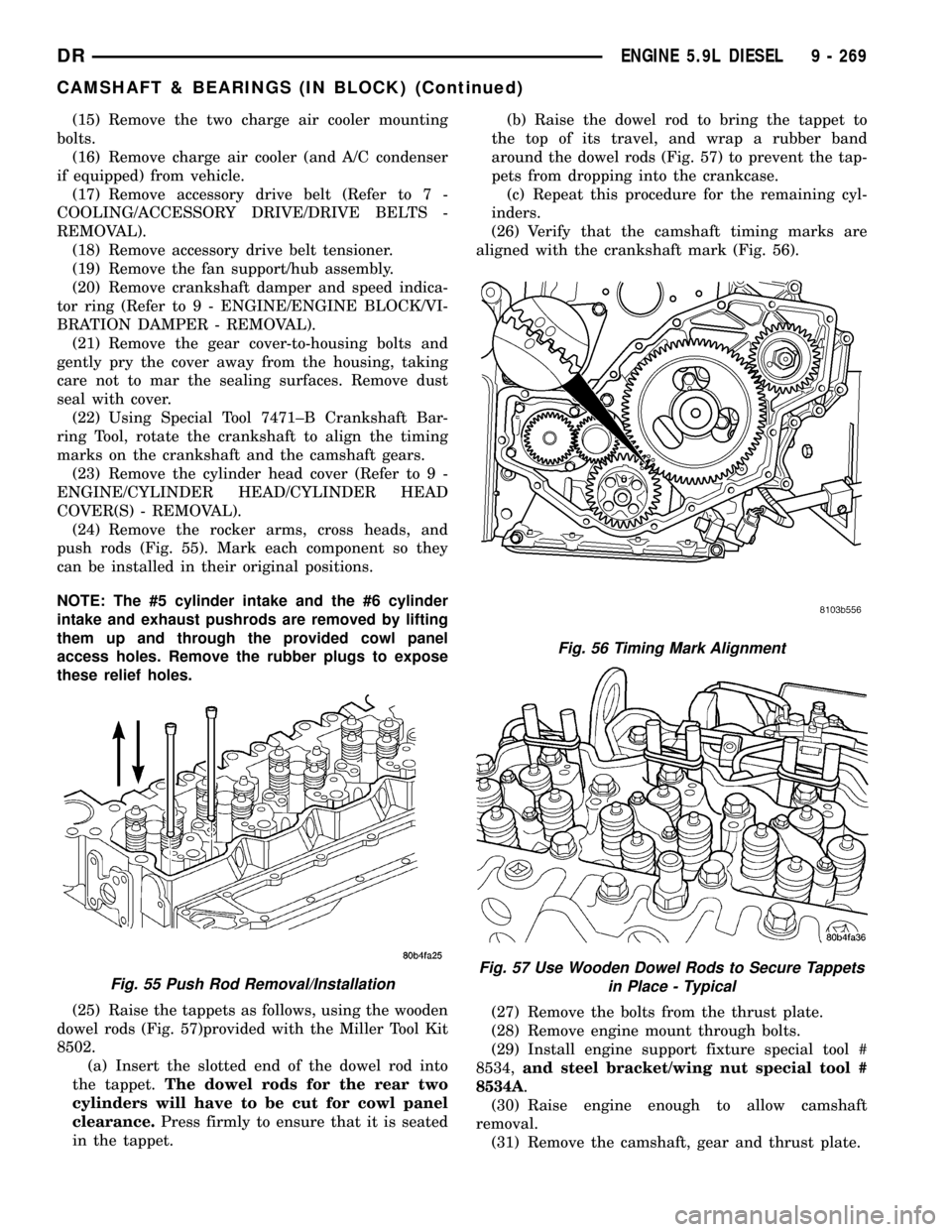
(24) Remove the rocker arms, cross heads, and
push rods (Fig. 55). Mark each component so they
can be installed in their original positions.
NOTE: The #5 cylinder intake and the #6 cylinder
intake and exhaust pushrods are removed by lifting
them up and through the provided cowl panel
access holes. Remove the rubber plugs to expose
these relief holes.
(25) Raise the tappets as follows, using the wooden
dowel rods (Fig. 57)provided with the Miller Tool Kit
8502.
(a) Insert the slotted end of the dowel rod into
the tappet.The dowel rods for the rear two
cylinders will have to be cut for cowl panel
clearance.Press firmly to ensure that it is seated
in the tappet.(b) Raise the dowel rod to bring the tappet to
the top of its travel, and wrap a rubber band
around the dowel rods (Fig. 57) to prevent the tap-
pets from dropping into the crankcase.
(c) Repeat this procedure for the remaining cyl-
inders.
(26) Verify that the camshaft timing marks are
aligned with the crankshaft mark (Fig. 56).
(27) Remove the bolts from the thrust plate.
(28) Remove engine mount through bolts.
(29) Install engine support fixture special tool #
8534,and steel bracket/wing nut special tool #
8534A.
(30) Raise engine enough to allow camshaft
removal.
(31) Remove the camshaft, gear and thrust plate.
Fig. 55 Push Rod Removal/Installation
Fig. 56 Timing Mark Alignment
Fig. 57 Use Wooden Dowel Rods to Secure Tappets
in Place - Typical
DRENGINE 5.9L DIESEL 9 - 269
CAMSHAFT & BEARINGS (IN BLOCK) (Continued)
Page 1495 of 2627
(6) Remove the wooden dowel rods and rubber
bands from the tappets.
(7) Lubricate the push rods with engine oil and
install in their original location.Verify that they
are seated in the tappets.
(8) Lubricate the valve tips with engine oil and
install the crossheads in their original locations.
(9) Lubricate the crossheads and push rod sockets
with engine oil and install the rocker arms and ped-
estals in their original locations. Tighten bolts to 36
N´m (27 ft. lbs.) torque.
(10)Verify valve lash adjustment (Refer to 9 -
ENGINE/CYLINDER HEAD/INTAKE/EXHAUST
VALVES & SEATS - STANDARD PROCEDURE).
(11) Install the cylinder head cover and reusable
gasket (Refer to 9 - ENGINE/CYLINDER HEAD/
CYLINDER HEAD COVER(S) - INSTALLATION).
(12) Install gear housing cover (Refer to 9 -
ENGINE/VALVE TIMING/GEAR HOUSING COVER
- INSTALLATION). Install front crankshaft dust
seal.
(13) Install the crankshaft damper with the speed
indicator ring (Refer to 9 - ENGINE/ENGINE
BLOCK/VIBRATION DAMPER - INSTALLATION).
(14) Install the fan support/hub assembly Refer to
(Refer to 7 - COOLING/ENGINE/RADIATOR FAN -
INSTALLATION).
(15) Install the power steering pump.
(16) Install accessory drive belt tensioner. Torque
bolt to 43 Nm (32 ft. lbs.).
(17) Install the accessory drive belt (Refer to 7 -
COOLING/ACCESSORY DRIVE/DRIVE BELTS -
INSTALLATION).
(18) Install the charge air cooler (with a/c con-
denser and auxiliary transmission oil cooler, if
equipped) and tighten the mounting bolts to 2 N´m
(17 in. lbs.) torque.
(19) Connect charge air cooler inlet and outlet
pipes. Tighten clamps to 11 N´m (95 in. lbs.) torque.
(20) Install the radiator upper support panel.
(21) Close radiator petcock and lower the radiator
into the engine compartment. Tighten the mounting
bolts to 11 N´m (95 in. lbs.) torque.
(22) Raise vehicle on hoist.
(23) Connect radiator lower hose and install
clamp.
(24) Connect transmission auxiliary oil cooler lines
(if equipped).
(25) Lower vehicle.
(26) Install the fan shroud and tighten the mount-
ing screws to 6 N´m (50 in. lbs.) torque.
(27) Install the electronically controlled viscous
fan/drive assembly. Connect harness connector.(Refer
to 7 - COOLING/ENGINE/RADIATOR FAN -
INSTALLATION).(28) Install the coolant recovery and windshield
washer fluid reservoirs to the fan shroud.
(29) Connect the coolant recovery hose to the radi-
ator filler neck.
(30) Add engine coolant (Refer to 7 - COOLING -
STANDARD PROCEDURE).
(31) Charge A/C system with refrigerant (if A/C
equipped) (Refer to 24 - HEATING & AIR CONDI-
TIONING/PLUMBING - STANDARD PROCEDURE).
(32) Connect the battery negative cables.
(33) Start engine and check for engine oil and cool-
ant leaks.
CONNECTING ROD BEARINGS
STANDARD PROCEDURE - CONNECTING ROD
BEARING AND CRANKSHAFT JOURNAL
CLEARANCE
(1) Measure the connecting rod bore with bearings
removedand the bolts tightened to 100 N´m (73 ft.
lbs.) torque..
(2) Measure the connecting rod bore with the bear-
ingsinstalledand the bolts tightened to 100 N´m
(73 ft. lbs.) torque.
Measure within 20É arc from each side of the part-
ing line. Also measure 90É from parting line.
Record the smallest and largest diameter.
Measure the diameter of the rod journal at the
location shown (Fig. 63). Calculate the average diam-
eter for each side of the journal.
Determine minimum bearing clearance by calculat-
ing the differance between the smallest connecting
rod bore diameter with the bearing installed and the
average diameter for each side of the crankshaft jour-
nal.
Determine the maximum bearing clearance by cal-
culating the difference between the largest connect-
ing rod bore diameter and the average diameter with
the bearing installed for each side of the crankshaft
journal.
DESCRIPTION MEASUREMENT
CONNECTING ROD
BORE, BEARINGS
REMOVEDMIN. 72.99 mm (2.874
in.)
MAX. 73.01 mm (2.875
in.)
CONNECTING ROD
BORE, BEARINGS
INSTALLEDMIN. 69.05 mm (2.719
in.)
MAX. 69.10 mm (2.720
in.)
9 - 272 ENGINE 5.9L DIESELDR
CAMSHAFT & BEARINGS (IN BLOCK) (Continued)
Page 1517 of 2627
OIL PRESSURE RELIEF VALVE
REMOVAL
(1) Disconnect the battery negative cables.
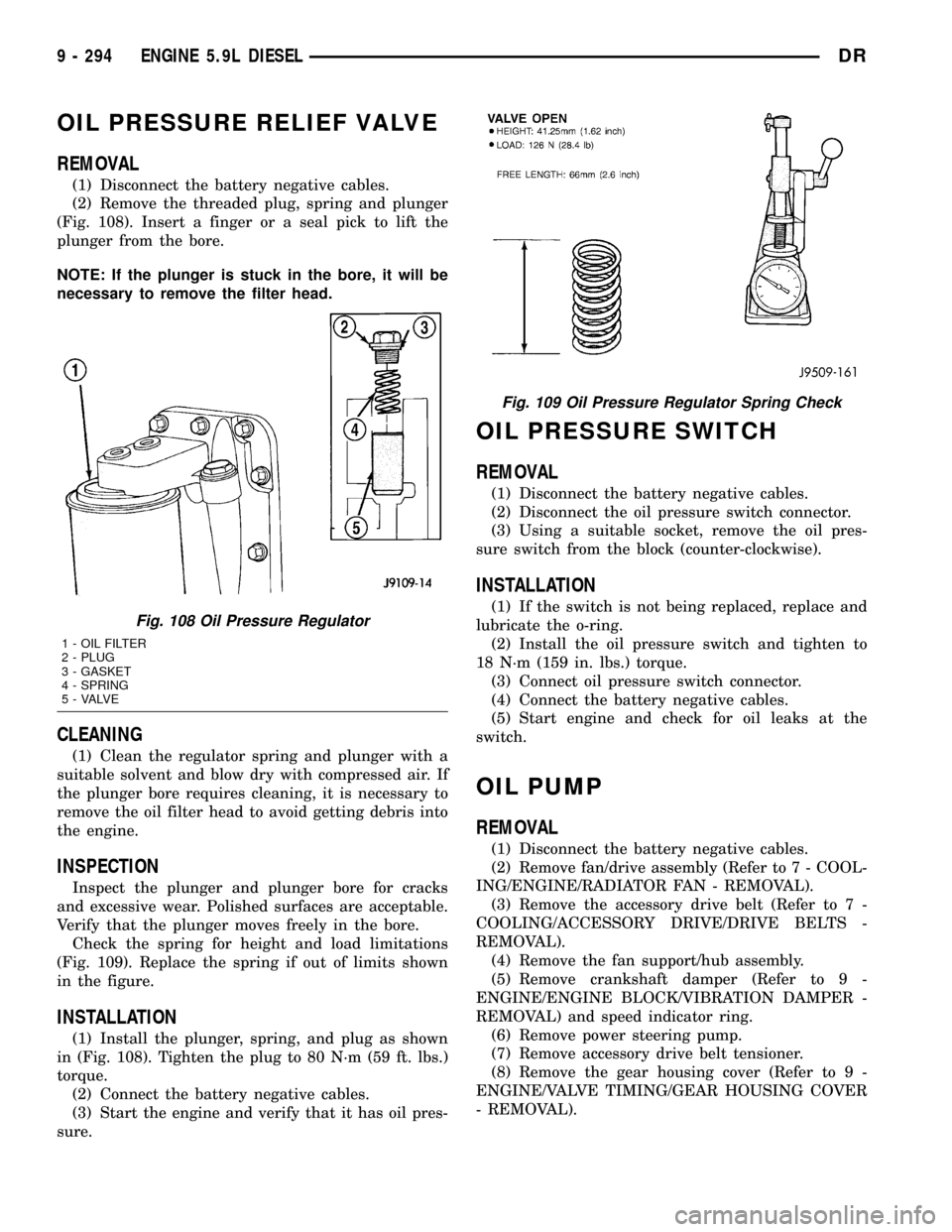
(2) Remove the threaded plug, spring and plunger
(Fig. 108). Insert a finger or a seal pick to lift the
plunger from the bore.
NOTE: If the plunger is stuck in the bore, it will be
necessary to remove the filter head.
CLEANING
(1) Clean the regulator spring and plunger with a
suitable solvent and blow dry with compressed air. If
the plunger bore requires cleaning, it is necessary to
remove the oil filter head to avoid getting debris into
the engine.
INSPECTION
Inspect the plunger and plunger bore for cracks
and excessive wear. Polished surfaces are acceptable.
Verify that the plunger moves freely in the bore.
Check the spring for height and load limitations
(Fig. 109). Replace the spring if out of limits shown
in the figure.
INSTALLATION
(1) Install the plunger, spring, and plug as shown
in (Fig. 108). Tighten the plug to 80 N´m (59 ft. lbs.)
torque.
(2) Connect the battery negative cables.
(3) Start the engine and verify that it has oil pres-
sure.
OIL PRESSURE SWITCH
REMOVAL
(1) Disconnect the battery negative cables.
(2) Disconnect the oil pressure switch connector.
(3) Using a suitable socket, remove the oil pres-
sure switch from the block (counter-clockwise).
INSTALLATION
(1) If the switch is not being replaced, replace and
lubricate the o-ring.
(2) Install the oil pressure switch and tighten to
18 N´m (159 in. lbs.) torque.
(3) Connect oil pressure switch connector.
(4) Connect the battery negative cables.
(5) Start engine and check for oil leaks at the
switch.
OIL PUMP
REMOVAL
(1) Disconnect the battery negative cables.
(2) Remove fan/drive assembly (Refer to 7 - COOL-
ING/ENGINE/RADIATOR FAN - REMOVAL).
(3) Remove the accessory drive belt (Refer to 7 -
COOLING/ACCESSORY DRIVE/DRIVE BELTS -
REMOVAL).
(4) Remove the fan support/hub assembly.
(5) Remove crankshaft damper (Refer to 9 -
ENGINE/ENGINE BLOCK/VIBRATION DAMPER -
REMOVAL) and speed indicator ring.
(6) Remove power steering pump.
(7) Remove accessory drive belt tensioner.
(8) Remove the gear housing cover (Refer to 9 -
ENGINE/VALVE TIMING/GEAR HOUSING COVER
- REMOVAL).
Fig. 108 Oil Pressure Regulator
1 - OIL FILTER
2 - PLUG
3 - GASKET
4 - SPRING
5 - VALVE
Fig. 109 Oil Pressure Regulator Spring Check
9 - 294 ENGINE 5.9L DIESELDR