1998 DODGE RAM 1500 door lock
[x] Cancel search: door lockPage 1121 of 2627
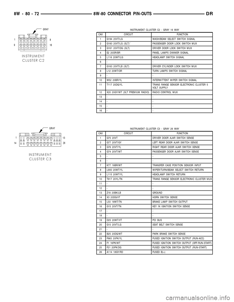
INSTRUMENT CLUSTER C2 - GRAY 16 WAY
CAV CIRCUIT FUNCTION
1 G194 20VT/LG WASH/BEAM SELECT SWITCH SIGNAL
2 G160 20VT/LG (SLT)8PASSENGER DOOR LOCK SWITCH MUX
3 G161 20VT/DG (SLT) DRIVER DOOR LOCK SWITCH MUX
4 E2 20OR/BR PANEL LAMPS DIMMER SIGNAL
5 L116 20WT/LG HEADLAMP SWITCH SIGNAL
6- -
7 G163 20VT/LB (SLT) DRIVER CYLINDER LOCK SWITCH MUX
8 L12 20WT/OR TURN LAMPS SWITCH SIGNAL
9- -
10 W52 20BR/YL INTERMITTENT WIPER SWITCH SIGNAL
11 T117 20DG/YL TRANS RANGE SENSOR ELECTRONIC CLUSTER 5
VOLT SUPPLY
12 X20 20GY/WT (SLT PREMIUM RADIO) RADIO CONTROL MUX
13 - -
14 - -
15 - -
16 - -
INSTRUMENT CLUSTER C3 - GRAY 26 WAY
CAV CIRCUIT FUNCTION
1 G75 20VT DRIVER DOOR AJAR SWITCH SENSE
2 G77 20VT/GY LEFT REAR DOOR AJAR SWITCH SENSE
3 G76 20VT/YL RIGHT REAR DOOR AJAR SWITCH SENSE
4 G74 20VT/WT PASSENGER DOOR AJAR SWITCH SENSE
5- -
6- -
7 K77 18BR/WT TRANSFER CASE POSITION SENSOR INPUT
8 L900 20WT/YL WIPER/TURN/BEAM SELECT SWITCH RETURN
9 L115 20WT/YL HEADLAMP SWITCH RETURN
10 T917 20YL/TN TRANS RANGE SENSOR ELECTRONIC CLUSTER MUX
11 - -
12 - -
13 Z18 20BK/LB GROUND
14 X3 20DG/VT HORN SWITCH SENSE
15 L50 18WT/TN BRAKE LAMP SWITCH OUTPUT
16 G15 20VT/TN KEY IN IGNITION SWITCH SENSE
17 - -
18 - -
19 D25 20WT/VT PCI BUS
20 G10 20VT/LG SEAT BELT SWITCH SENSE
21 - -
22 B25 20DG/WT PARK BRAKE SWITCH SENSE
23 F983 20PK/YL FUSED IGNITION SWITCH OUTPUT (RUN-ACC)
24 F1 16PK/WT FUSED IGNITION SWITCH OUTPUT (OFF-RUN-START)
25 F21 20PK/DG FUSED IGNITION SWITCH OUTPUT (RUN-START)
26 A114 18GY/RD FUSED B(+)
8W - 80 - 72 8W-80 CONNECTOR PIN-OUTSDR
Page 1155 of 2627
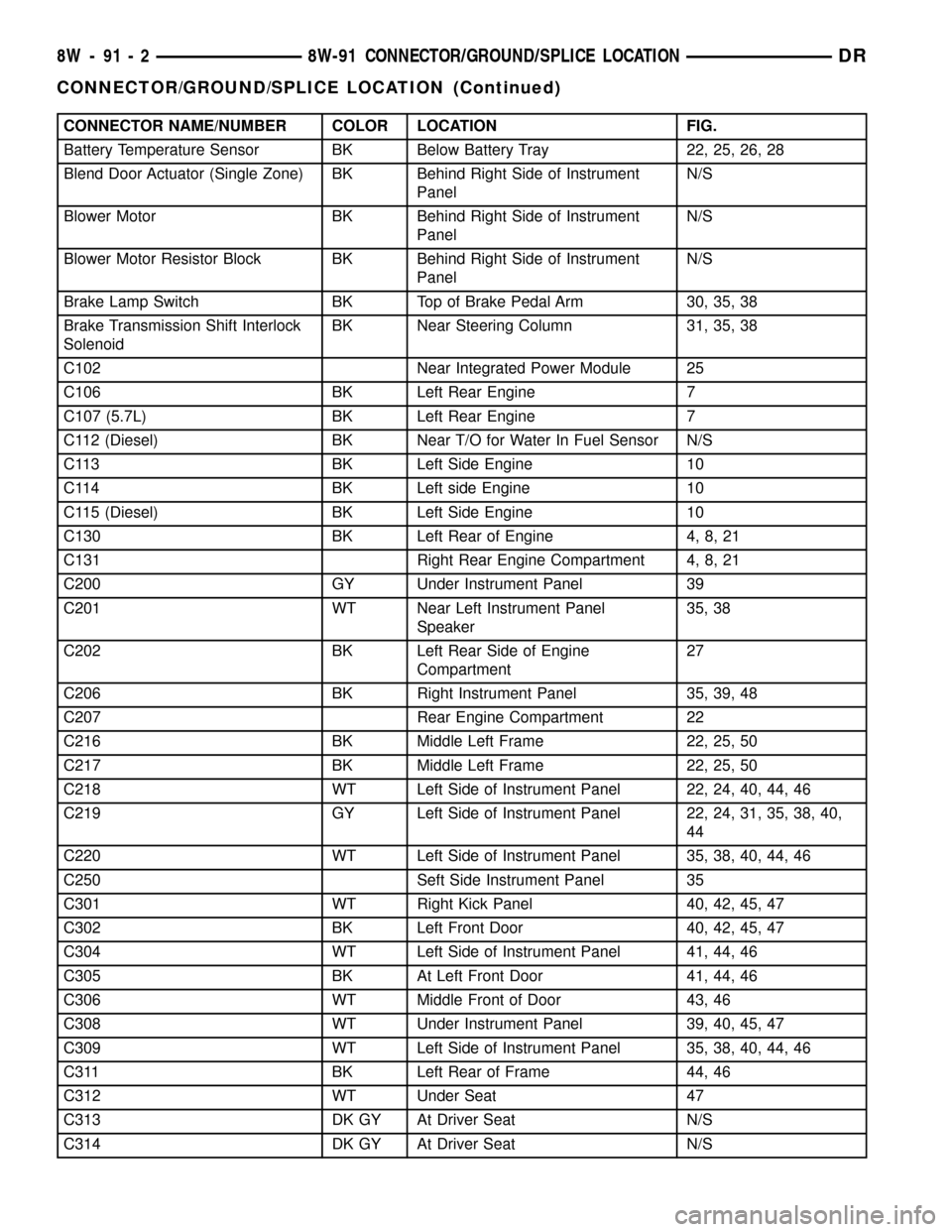
CONNECTOR NAME/NUMBER COLOR LOCATION FIG.
Battery Temperature Sensor BK Below Battery Tray 22, 25, 26, 28
Blend Door Actuator (Single Zone) BK Behind Right Side of Instrument
PanelN/S
Blower Motor BK Behind Right Side of Instrument
PanelN/S
Blower Motor Resistor Block BK Behind Right Side of Instrument
PanelN/S
Brake Lamp Switch BK Top of Brake Pedal Arm 30, 35, 38
Brake Transmission Shift Interlock
SolenoidBK Near Steering Column 31, 35, 38
C102 Near Integrated Power Module 25
C106 BK Left Rear Engine 7
C107 (5.7L) BK Left Rear Engine 7
C112 (Diesel) BK Near T/O for Water In Fuel Sensor N/S
C113 BK Left Side Engine 10
C114 BK Left side Engine 10
C115 (Diesel) BK Left Side Engine 10
C130 BK Left Rear of Engine 4, 8, 21
C131 Right Rear Engine Compartment 4, 8, 21
C200 GY Under Instrument Panel 39
C201 WT Near Left Instrument Panel
Speaker35, 38
C202 BK Left Rear Side of Engine
Compartment27
C206 BK Right Instrument Panel 35, 39, 48
C207 Rear Engine Compartment 22
C216 BK Middle Left Frame 22, 25, 50
C217 BK Middle Left Frame 22, 25, 50
C218 WT Left Side of Instrument Panel 22, 24, 40, 44, 46
C219 GY Left Side of Instrument Panel 22, 24, 31, 35, 38, 40,
44
C220 WT Left Side of Instrument Panel 35, 38, 40, 44, 46
C250 Seft Side Instrument Panel 35
C301 WT Right Kick Panel 40, 42, 45, 47
C302 BK Left Front Door 40, 42, 45, 47
C304 WT Left Side of Instrument Panel 41, 44, 46
C305 BK At Left Front Door 41, 44, 46
C306 WT Middle Front of Door 43, 46
C308 WT Under Instrument Panel 39, 40, 45, 47
C309 WT Left Side of Instrument Panel 35, 38, 40, 44, 46
C311 BK Left Rear of Frame 44, 46
C312 WT Under Seat 47
C313 DK GY At Driver Seat N/S
C314 DK GY At Driver Seat N/S
8W - 91 - 2 8W-91 CONNECTOR/GROUND/SPLICE LOCATIONDR
CONNECTOR/GROUND/SPLICE LOCATION (Continued)
Page 1156 of 2627
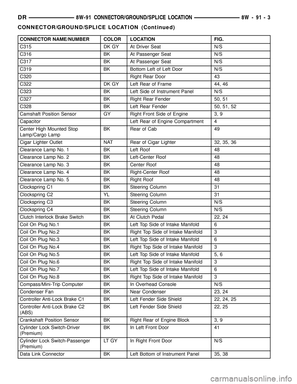
CONNECTOR NAME/NUMBER COLOR LOCATION FIG.
C315 DK GY At Driver Seat N/S
C316 BK At Passenger Seat N/S
C317 BK At Passenger Seat N/S
C319 BK Bottom Left of Left Door N/S
C320 Right Rear Door 43
C322 DK GY Left Rear of Frame 44, 46
C323 BK Left Side of Instrument Panel N/S
C327 BK Right Rear Fender 50, 51
C328 BK Left Rear Fender 50, 51, 52
Camshaft Position Sensor GY Right Front Side of Engine 3, 9
Capacitor Left Rear of Engine Compartment 4
Center High Mounted Stop
Lamp/Cargo LampBK Rear of Cab 49
Cigar Lighter Outlet NAT Rear of Cigar Lighter 32, 35, 36
Clearance Lamp No. 1 BK Left Roof 48
Clearance Lamp No. 2 BK Left-Center Roof 48
Clearance Lamp No. 3 BK Center Roof 48
Clearance Lamp No. 4 BK Right-Center Roof 48
Clearance Lamp No. 5 BK Right Roof 48
Clockspring C1 BK Steering Column 31
Clockspring C2 YL Steering Column 31
Clockspring C3 BK Steering Column N/S
Clockspring C4 BK Steering Column N/S
Clutch Interlock Brake Switch BK At Clutch Pedal 22, 24
Coil On Plug No.1 BK Left Top Side of Intake Manifold 6
Coil On Plug No.2 BK Right Top Side of Intake Manifold 3
Coil On Plug No.3 BK Left Top Side of Intake Manifold 6
Coil On Plug No.4 BK Right Top Side of Intake Manifold 3
Coil On Plug No.5 BK Left Top Side of Intake Manifold 5, 6
Coil On Plug No.6 BK Right Top Side of Intake Manifold 3
Coil On Plug No.7 BK Left Top Side of Intake Manifold 6
Coil On Plug No.8 BK Right Top Side of Intake Manifold 3
Compass/Mini-Trip Computer BK In Overhead Console N/S
Condenser Fan BK Near Condenser 23, 24
Controller Anti-Lock Brake C1 BK Left Fender Side Shield 22, 24, 25
Controller Anti-Lock Brake C2
(ABS)BK Left Fender Side Shield 22, 25
Crankshaft Position Sensor BK Right Rear of Engine Block 3, 9
Cylinder Lock Switch-Driver
(Premium)BK In Left Front Door 41
Cylinder Lock Switch-Passenger
(Premium)LT GY In Right Front Door N/S
Data Link Connector BK Left Bottom of Instrument Panel 35, 38
DR8W-91 CONNECTOR/GROUND/SPLICE LOCATION 8W - 91 - 3
CONNECTOR/GROUND/SPLICE LOCATION (Continued)
Page 1157 of 2627
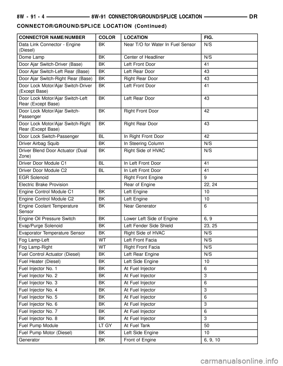
CONNECTOR NAME/NUMBER COLOR LOCATION FIG.
Data Link Connector - Engine
(Diesel)BK Near T/O for Water In Fuel Sensor N/S
Dome Lamp BK Center of Headliner N/S
Door Ajar Switch-Driver (Base) BK Left Front Door 41
Door Ajar Switch-Left Rear (Base) BK Left Rear Door 43
Door Ajar Switch-Right Rear (Base) BK Right Rear Door 43
Door Lock Motor/Ajar Switch-Driver
(Except Base)BK Left Front Door 41
Door Lock Motor/Ajar Switch-Left
Rear (Except Base)BK Left Rear Door 43
Door Lock Motor/Ajar Switch-
PassengerBK Right Front Door 42
Door Lock Motor/Ajar Switch-Right
Rear (Except Base)BK Right Rear Door 43
Door Lock Switch-Passenger BL In Right Front Door 42
Driver Airbag Squib BK In Steering Column N/S
Driver Blend Door Actuator (Dual
Zone)BK Right Side of HVAC N/S
Driver Door Module C1 BL In Left Front Door 41
Driver Door Module C2 BL In Left Front Door 41
EGR Solenoid Right Front Engine 9
Electric Brake Provision Rear of Engine 22, 24
Engine Control Module C1 BK Left Engine 10
Engine Control Module C2 BK Left Engine 10
Engine Coolant Temperature
SensorBK Near Generator 6
Engine Oil Pressure Switch BK Lower Left Side of Engine 6, 9
Evap/Purge Solenoid BK Left Fender Side Shield 23, 25
Evaporator Temperature Sensor BK Right Side of HVAC N/S
Fog Lamp-Left WT Left Front Facia N/S
Fog Lamp-Right WT Right Front Facia N/S
Fuel Control Actuator (Diesel) BK Left Rear Engine N/S
Fuel Heater (Diesel) BK Left Side Engine 10
Fuel Injector No. 1 BK At Fuel Injector 6
Fuel Injector No. 2 BK At Fuel Injector 3
Fuel Injector No. 3 BK At Fuel Injector 6
Fuel Injector No. 4 BK At Fuel Injector 3
Fuel Injector No. 5 BK At Fuel Injector 6
Fuel Injector No. 6 BK At Fuel Injector 3
Fuel Injector No. 7 BK At Fuel Injector 6
Fuel Injector No. 8 BK At Fuel Injector 3
Fuel Pump Module LT GY At Fuel Tank 50
Fuel Pump Motor (Diesel) BK Left Side Engine 10
Generator BK Front of Engine 6, 9, 10
8W - 91 - 4 8W-91 CONNECTOR/GROUND/SPLICE LOCATIONDR
CONNECTOR/GROUND/SPLICE LOCATION (Continued)
Page 1571 of 2627
OPERATION
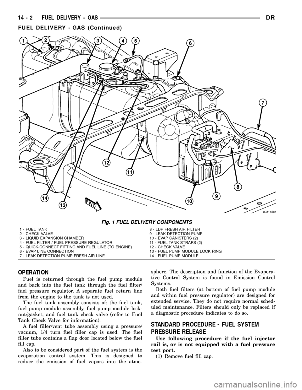
Fuel is returned through the fuel pump module
and back into the fuel tank through the fuel filter/
fuel pressure regulator. A separate fuel return line
from the engine to the tank is not used.
The fuel tank assembly consists of: the fuel tank,
fuel pump module assembly, fuel pump module lock-
nut/gasket, and fuel tank check valve (refer to Fuel
Tank Check Valve for information).
A fuel filler/vent tube assembly using a pressure/
vacuum, 1/4 turn fuel filler cap is used. The fuel
filler tube contains a flap door located below the fuel
fill cap.
Also to be considered part of the fuel system is the
evaporation control system. This is designed to
reduce the emission of fuel vapors into the atmo-sphere. The description and function of the Evapora-
tive Control System is found in Emission Control
Systems.
Both fuel filters (at bottom of fuel pump module
and within fuel pressure regulator) are designed for
extended service. They do not require normal sched-
uled maintenance. Filters should only be replaced if
a diagnostic procedure indicates to do so.
STANDARD PROCEDURE - FUEL SYSTEM
PRESSURE RELEASE
Use following procedure if the fuel injector
rail is, or is not equipped with a fuel pressure
test port.
(1) Remove fuel fill cap.
Fig. 1 FUEL DELIVERY COMPONENTS
1 - FUEL TANK 8 - LDP FRESH AIR FILTER
2 - CHECK VALVE 9 - LEAK DETECTION PUMP
3 - LIQUID EXPANSION CHAMBER 10 - EVAP CANISTERS (2)
4 - FUEL FILTER / FUEL PRESSURE REGULATOR 11 - FUEL TANK STRAPS (2)
5 - QUICK-CONNECT FITTING AND FUEL LINE (TO ENGINE) 12 - CHECK VALVE
6 - EVAP LINE CONNECTION 13 - FUEL PUMP MODULE LOCK RING
7 - LEAK DETECTION PUMP FRESH AIR LINE 14 - FUEL PUMP MODULE
14 - 2 FUEL DELIVERY - GASDR
FUEL DELIVERY - GAS (Continued)
Page 1586 of 2627
(15) Install air duct to air box.
(16) Connect battery cable to battery.
(17) Start engine and check for leaks.
5.7L V-8
(1) If fuel injectors are to be installed, refer to Fuel
Injector Removal/Installation.
(2) Clean out fuel injector machined bores in
intake manifold.
(3) Apply a small amount of engine oil to each fuel
injector o-ring. This will help in fuel rail installation.
(4) Position fuel rail/fuel injector assembly to
machined injector openings in intake manifold.
(5) Guide each injector into intake manifold. Be
careful not to tear injector o-rings.
(6) Pushrightside of fuel rail down until fuel
injectors have bottomed on shoulders. Pushleftfuel
rail down until injectors have bottomed on shoulders.
(7) Install 4 fuel rail holdown clamps and 4 mount-
ing bolts. Refer to Torque Specifications.
(8) Position spark plug cable tray and cable assem-
bly to intake manifold. Snap 4 cable tray retaining
clips into intake manifold.
(9) Install all cables to spark plugs and ignition
coils.
(10) Connect electrical connector to throttle body.
(11) Install electrical connectors to all 8 ignition
coils. Refer to Ignition Coil Removal/Installation.
(12) Connect electrical connector to throttle body.
(13) Connect electrical connectors at all fuel injec-
tors. To install connector, refer to (Fig. 17). Push con-
nector onto injector (1) and then push and lock red
colored slider (2). Verify connector is locked to injec-
tor by lightly tugging on connector.
(14) Connect fuel line latch clip and fuel line to
fuel rail. Refer to Quick-Connect Fittings.
(15) Install air resonator to throttle body (2 bolts).
(16) Install flexible air duct to air box.
(17) Connect battery cable to battery.
(18) Start engine and check for leaks.
FUEL TANK
DESCRIPTION
The fuel tank is constructed of a plastic material.
Its main functions are for fuel storage and for place-
ment of the fuel pump module, and (if equipped) cer-
tain ORVR components.
OPERATION
All models pass a full 360 degree rollover test
without fuel leakage. To accomplish this, fuel and
vapor flow controls are required for all fuel tank con-
nections.Two check (control) valves are mounted into the
top of the fuel tank. Refer to Fuel Tank Check Valve
for additional information.
An evaporation control system is connected to the
fuel tank to reduce emissions of fuel vapors into the
atmosphere. When fuel evaporates from the fuel
tank, vapors pass through vent hoses or tubes to a
charcoal canister where they are temporarily held.
When the engine is running, the vapors are drawn
into the intake manifold. Certain models are also
equipped with a self-diagnosing system using a Leak
Detection Pump (LDP) and/or an On-Board Refueling
Vapor Recovery (ORVR) system. Refer to Emission
Control System for additional information.
REMOVAL- EXCEPT DIESEL
Fuel Tank Draining
WARNING: THE FUEL SYSTEM MAY BE UNDER
CONSTANT FUEL PRESSURE EVEN WITH THE
ENGINE OFF. THIS PRESSURE MUST BE
RELEASED BEFORE SERVICING FUEL TANK.
Two different procedures may be used to drain fuel
tank: through the fuel fill fitting on tank, or using
the DRBtscan tool. Due to a one-way check valve
installed into the fuel fill opening fitting at the tank,
the tank cannot be drained conventionally at the fill
cap.
The quickest draining procedure involves removing
the rubber fuel fill hose.
As an alternative procedure, the electric fuel pump
may be activated allowing tank to be drained at fuel
rail connection. Refer to DRB scan tool for fuel pump
activation procedures. Before disconnecting fuel line
at fuel rail, release fuel pressure. Refer to the Fuel
System Pressure Release Procedure for procedures.
Attach end of special test hose tool number 6541,
6539, 6631 or 6923 at fuel rail disconnection (tool
number will depend on model and/or engine applica-
tion). Position opposite end of this hose tool to an
approved gasoline draining station. Activate fuel
pump and drain tank until empty.
If electric fuel pump is not operating, fuel must be
drained through fuel fill fitting at tank. Refer to fol-
lowing procedures.
(1) Release fuel system pressure.
(2) Raise vehicle.
(3) Thoroughly clean area around fuel fill fitting
and rubber fuel fill hose at tank.
(4) If vehicle is equipped with 4 doors and a 6 foot
(short) box, remove left-rear tire/wheel.
(5) Loosen clamp (Fig. 23) and disconnect rubber
fuel fill hose at tank fitting. Using an approved gas
holding tank, drain fuel tank through this fitting.
DRFUEL DELIVERY - GAS 14 - 17
FUEL RAIL (Continued)
Page 1592 of 2627
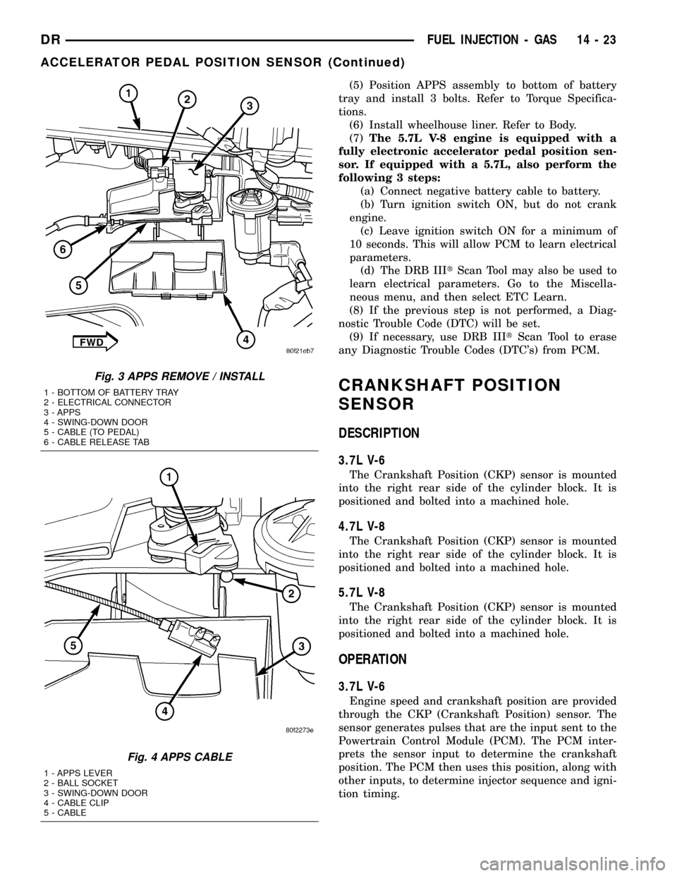
(5) Position APPS assembly to bottom of battery
tray and install 3 bolts. Refer to Torque Specifica-
tions.
(6) Install wheelhouse liner. Refer to Body.
(7)The 5.7L V-8 engine is equipped with a
fully electronic accelerator pedal position sen-
sor. If equipped with a 5.7L, also perform the
following 3 steps:
(a) Connect negative battery cable to battery.
(b) Turn ignition switch ON, but do not crank
engine.
(c) Leave ignition switch ON for a minimum of
10 seconds. This will allow PCM to learn electrical
parameters.
(d) The DRB IIItScan Tool may also be used to
learn electrical parameters. Go to the Miscella-
neous menu, and then select ETC Learn.
(8) If the previous step is not performed, a Diag-
nostic Trouble Code (DTC) will be set.
(9) If necessary, use DRB IIItScan Tool to erase
any Diagnostic Trouble Codes (DTC's) from PCM.
CRANKSHAFT POSITION
SENSOR
DESCRIPTION
3.7L V-6
The Crankshaft Position (CKP) sensor is mounted
into the right rear side of the cylinder block. It is
positioned and bolted into a machined hole.
4.7L V-8
The Crankshaft Position (CKP) sensor is mounted
into the right rear side of the cylinder block. It is
positioned and bolted into a machined hole.
5.7L V-8
The Crankshaft Position (CKP) sensor is mounted
into the right rear side of the cylinder block. It is
positioned and bolted into a machined hole.
OPERATION
3.7L V-6
Engine speed and crankshaft position are provided
through the CKP (Crankshaft Position) sensor. The
sensor generates pulses that are the input sent to the
Powertrain Control Module (PCM). The PCM inter-
prets the sensor input to determine the crankshaft
position. The PCM then uses this position, along with
other inputs, to determine injector sequence and igni-
tion timing.
Fig. 3 APPS REMOVE / INSTALL
1 - BOTTOM OF BATTERY TRAY
2 - ELECTRICAL CONNECTOR
3 - APPS
4 - SWING-DOWN DOOR
5 - CABLE (TO PEDAL)
6 - CABLE RELEASE TAB
Fig. 4 APPS CABLE
1 - APPS LEVER
2 - BALL SOCKET
3 - SWING-DOWN DOOR
4 - CABLE CLIP
5 - CABLE
DRFUEL INJECTION - GAS 14 - 23
ACCELERATOR PEDAL POSITION SENSOR (Continued)
Page 1631 of 2627
FUEL TANK
DESCRIPTION - DIESEL
The fuel tank is similar to the tank used with gas-
oline powered models. The tank is equipped with a
separate fuel return line and a different fuel tank
module for diesel powered models. A fuel tank
mounted, electric fuel pump is not used with diesel
powered models. Refer to Fuel Tank Module for addi-
tional information.
REMOVAL - DIESEL
Fuel Tank Draining
Due to a one-way check valve installed into the
fuel fill opening fitting at the tank, the tank cannot
be drained conventionally at the fill cap.
(1) Raise vehicle.
(2) If vehicle is equipped with 4 doors and a 6 foot
(short) box, remove left-rear tire/wheel.
(3) Thoroughly clean area at top of fuel tank
around fuel tank module.
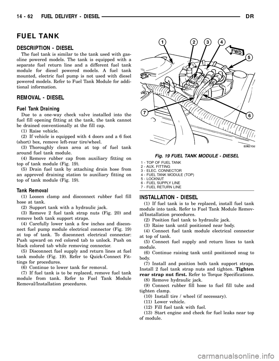
(4) Remove rubber cap from auxiliary fitting on
top of tank module (Fig. 19).
(5) Drain fuel tank by attaching drain hose from
an approved draining station to auxiliary fitting on
top of tank module (Fig. 19).
Tank Removal
(1) Loosen clamp and disconnect rubber fuel fill
hose at tank.
(2) Support tank with a hydraulic jack.
(3) Remove 2 fuel tank strap nuts (Fig. 20) and
remove both tank support straps.
(4) Carefully lower tank a few inches and discon-
nect fuel pump module electrical connector (Fig. 19)
at top of tank. To disconnect electrical connector:
Push upward on red colored tab to unlock. Push on
black colored tab while removing connector.
(5) Disconnect fuel supply and return lines at fuel
tank module (Fig. 19). Refer to Quick-Connect Fit-
tings for procedures.
(6) Continue to lower tank for removal.
(7) If fuel tank is to be replaced, remove fuel tank
module from tank. Refer to Fuel Tank Module
Removal/Installation procedures.INSTALLATION - DIESEL
(1) If fuel tank is to be replaced, install fuel tank
module into tank. Refer to Fuel Tank Module Remov-
al/Installation procedures.
(2) Position fuel tank to hydraulic jack.
(3) Raise tank until positioned near body.
(4) Connect fuel tank module electrical connector
at top of tank.
(5) Connect fuel supply and return lines to tank
module.
(6) Continue raising tank until positioned snug to
body.
(7) Install and position both tank support straps.
Install 2 fuel tank strap nuts and tighten.Tighten
rear strap nut first.Refer to Torque Specifications.
(8) Remove hydraulic jack.
(9) Connect rubber fill hose to fuel fill tube and
tighten clamp.
(10) Install tire / wheel (if necessary).
(11) Lower vehicle.
(12) Fill fuel tank with fuel.
(13) Start engine and check for fuel leaks near top
of module.
Fig. 19 FUEL TANK MODULE - DIESEL
1 - TOP OF FUEL TANK
2 - AUX. FITTING
3 - ELEC. CONNECTOR
4 - FUEL TANK MODULE (TOP)
5 - LOCKNUT
6 - FUEL SUPPLY LINE
7 - FUEL RETURN LINE
14 - 62 FUEL DELIVERY - DIESELDR