1998 DODGE RAM 1500 check oil
[x] Cancel search: check oilPage 567 of 2627

INSTALLATION
(1) Quarter twist the bulb socket clockwise into
the lamp housing.
(2) Position the lamp assembly onto the roof and
install retaining screws. (Fig. 7)
FOG LAMP
REMOVAL
NOTE: The fog lamps are serviced from the rear-
ward side of the front bumper.
(1) Disconnect and isolate the battery negative
cable.
(2) Disengage fog lamp harness connector.
(3) Remove the bolts attaching the fog lamp to the
bumper (Fig. 8).
(4) Separate fog lamp from bumper.
INSTALLATION
(1) Position fog lamp in bumper.
(2) Install the bolts attaching the fog lamp to the
bumper.
(3) Connect fog lamp harness connector.
(4) Connect the battery negative cable.(5) Check for proper operation and beam align-
ment.
FOG LAMP RELAY
DESCRIPTION
The front fog lamp relay is located in the Power
Distribution Center (PDC) in the engine compart-
Fig. 7 Clearance Lamp
1 - NUT
2 - CAB ROOF
3 - BULB SOCKET
4 - CLEARANCE LAMP
5 - SCREW
6 - BULB
Fig. 8 Fog Lamp
1 - SCREW
2 - FOG LAMP UNIT
3 - CONNECTOR
Fig. 9 ISO Micro Relay
30 - COMMON FEED
85 - COIL GROUND
86 - COIL BATTERY
87 - NORMALLY OPEN
87A - NORMALLY CLOSED
8L - 12 LAMPS/LIGHTING - EXTERIORDR
CAB CLEARANCE LAMP (Continued)
Page 673 of 2627

OPERATION
The seat belt tension reducer is controlled by a
ground signal received from the seat belt switch on
the seat belt switch sense circuit and a battery cur-
rent signal received from the ignition switch on the
fused ignition switch output (run-accessory) circuit.
When the seat belt switch is closed (the driver side
front seat belt is fastened) and the ignition switch is
in the On or Accessory positions, the seat belt tension
reducer solenoid is energized. When the solenoid is
energized, it actuates a mechanism within the driver
side front outboard seat belt retractor to reduce the
normal recoil spring tension exerted by the retractor
spool, which is designed to reel in the seat belt web-
bing onto the spool. When the driver side seat belt is
unbuckled or if the ignition switch is turned to any
position except On or Accessory, the tension reducer
solenoid is de-energized and the normal recoil spring
tension of the retractor is restored.
The action of the seat belt tension reducer results
in improved seat belt comfort for the driver. Reducing
the seat belt retractor recoil spring tension is desir-
able on standard cab models of this vehicle and not
on the quad cab model due to the different mounting
position required for the seat belt turning loop on the
B-pillar relative to the driver's seat position on the
standard cab model. The seat belt tension reducer
may be diagnosed using conventional diagnostic tools
and methods.
DIAGNOSIS AND TESTING - SEAT BELT
TENSION REDUCER
Refer to the appropriate wiring information. The
wiring information includes wiring diagrams, proper
wire and connector repair procedures, details of wire
harness routing and retention, connector pin-out
information and location views for the various wire
harness connectors, splices and grounds.
WARNING: TO AVOID PERSONAL INJURY OR
DEATH, ON VEHICLES EQUIPPED WITH AIRBAGS,
DISABLE THE SUPPLEMENTAL RESTRAINT SYS-
TEM BEFORE ATTEMPTING ANY STEERING
WHEEL, STEERING COLUMN, AIRBAG, SEAT BELT
TENSIONER, IMPACT SENSOR, OR INSTRUMENT
PANEL COMPONENT DIAGNOSIS OR SERVICE.
DISCONNECT AND ISOLATE THE BATTERY NEGA-
TIVE (GROUND) CABLE, THEN WAIT TWO MINUTES
FOR THE SYSTEM CAPACITOR TO DISCHARGE
BEFORE PERFORMING FURTHER DIAGNOSIS OR
SERVICE. THIS IS THE ONLY SURE WAY TO DIS-
ABLE THE SUPPLEMENTAL RESTRAINT SYSTEM.
FAILURE TO TAKE THE PROPER PRECAUTIONS
COULD RESULT IN ACCIDENTAL AIRBAG DEPLOY-
MENT.(1) Disconnect and isolate the battery negative
cable. Disconnect the body wire harness connector for
the seat belt tension reducer from the tension
reducer connector receptacle on the driver side front
outboard seat belt and retractor unit. Using an ohm-
meter, measure the resistance between the seat belt
switch sense circuit terminal pin and the fused igni-
tion switch output (run-accessory) circuit terminal
pin in the tension reducer connector receptacle on
the retractor. Resistance through the tension reducer
solenoid coil should be 53 ohms at 20É C (68É F). If
OK, go to Step 2. If not OK, replace the faulty driver
side front outboard seat belt and retractor unit.
(2) Check for continuity between the seat belt
switch sense circuit cavity of the body wire harness
connector for the seat belt tension reducer and a good
ground. There should be continuity with the driver
side front seat belt buckled, and no continuity with
the driver side front seat belt unbuckled. If OK, go to
Step 3. If not OK, repair the shorted or open seat
belt switch sense circuit between the tension reducer
and the seat belt switch as required.
(3) Reconnect the battery negative cable. Check for
battery current at the fused ignition switch output
(run-accessory) circuit of the body wire harness con-
nector for the seat belt tension reducer. There should
be battery current with the ignition switch in the On
or Accessory positions, and no battery current with
the ignition switch in any other position. If not OK,
repair the shorted or open fused ignition switch out-
put (run-accessory) circuit between the tension
reducer and the ignition switch as required.
8O - 54 RESTRAINTSDR
SEAT BELT TENSION REDUCER (Continued)
Page 1217 of 2627
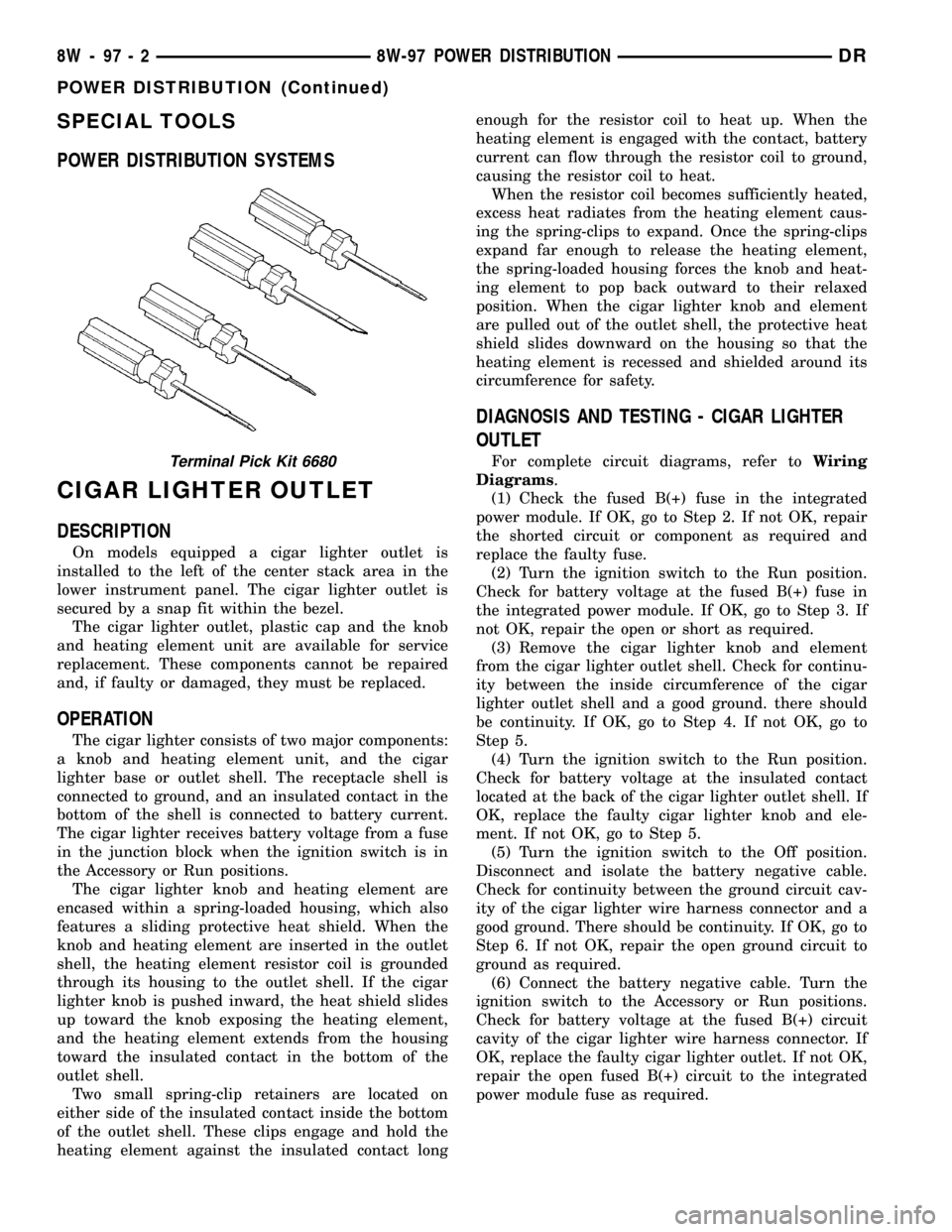
SPECIAL TOOLS
POWER DISTRIBUTION SYSTEMS
CIGAR LIGHTER OUTLET
DESCRIPTION
On models equipped a cigar lighter outlet is
installed to the left of the center stack area in the
lower instrument panel. The cigar lighter outlet is
secured by a snap fit within the bezel.
The cigar lighter outlet, plastic cap and the knob
and heating element unit are available for service
replacement. These components cannot be repaired
and, if faulty or damaged, they must be replaced.
OPERATION
The cigar lighter consists of two major components:
a knob and heating element unit, and the cigar
lighter base or outlet shell. The receptacle shell is
connected to ground, and an insulated contact in the
bottom of the shell is connected to battery current.
The cigar lighter receives battery voltage from a fuse
in the junction block when the ignition switch is in
the Accessory or Run positions.
The cigar lighter knob and heating element are
encased within a spring-loaded housing, which also
features a sliding protective heat shield. When the
knob and heating element are inserted in the outlet
shell, the heating element resistor coil is grounded
through its housing to the outlet shell. If the cigar
lighter knob is pushed inward, the heat shield slides
up toward the knob exposing the heating element,
and the heating element extends from the housing
toward the insulated contact in the bottom of the
outlet shell.
Two small spring-clip retainers are located on
either side of the insulated contact inside the bottom
of the outlet shell. These clips engage and hold the
heating element against the insulated contact longenough for the resistor coil to heat up. When the
heating element is engaged with the contact, battery
current can flow through the resistor coil to ground,
causing the resistor coil to heat.
When the resistor coil becomes sufficiently heated,
excess heat radiates from the heating element caus-
ing the spring-clips to expand. Once the spring-clips
expand far enough to release the heating element,
the spring-loaded housing forces the knob and heat-
ing element to pop back outward to their relaxed
position. When the cigar lighter knob and element
are pulled out of the outlet shell, the protective heat
shield slides downward on the housing so that the
heating element is recessed and shielded around its
circumference for safety.
DIAGNOSIS AND TESTING - CIGAR LIGHTER
OUTLET
For complete circuit diagrams, refer toWiring
Diagrams.
(1) Check the fused B(+) fuse in the integrated
power module. If OK, go to Step 2. If not OK, repair
the shorted circuit or component as required and
replace the faulty fuse.
(2) Turn the ignition switch to the Run position.
Check for battery voltage at the fused B(+) fuse in
the integrated power module. If OK, go to Step 3. If
not OK, repair the open or short as required.
(3) Remove the cigar lighter knob and element
from the cigar lighter outlet shell. Check for continu-
ity between the inside circumference of the cigar
lighter outlet shell and a good ground. there should
be continuity. If OK, go to Step 4. If not OK, go to
Step 5.
(4) Turn the ignition switch to the Run position.
Check for battery voltage at the insulated contact
located at the back of the cigar lighter outlet shell. If
OK, replace the faulty cigar lighter knob and ele-
ment. If not OK, go to Step 5.
(5) Turn the ignition switch to the Off position.
Disconnect and isolate the battery negative cable.
Check for continuity between the ground circuit cav-
ity of the cigar lighter wire harness connector and a
good ground. There should be continuity. If OK, go to
Step 6. If not OK, repair the open ground circuit to
ground as required.
(6) Connect the battery negative cable. Turn the
ignition switch to the Accessory or Run positions.
Check for battery voltage at the fused B(+) circuit
cavity of the cigar lighter wire harness connector. If
OK, replace the faulty cigar lighter outlet. If not OK,
repair the open fused B(+) circuit to the integrated
power module fuse as required.Terminal Pick Kit 6680
8W - 97 - 2 8W-97 POWER DISTRIBUTIONDR
POWER DISTRIBUTION (Continued)
Page 1225 of 2627
REMOVAL.............................38
INSTALLATION.........................38
ENGINE BLOCK
DESCRIPTION.........................38
STANDARD PROCEDURE - CYLINDER BORE
HONING............................38
CLEANING............................39
INSPECTION..........................39
CRANKSHAFT
DESCRIPTION.........................40
REMOVAL.............................40
INSPECTION..........................41
INSTALLATION.........................42
CRANKSHAFT MAIN BEARINGS
STANDARD PROCEDURE
MAIN BEARING FITTING................44
CRANKSHAFT OIL SEAL - FRONT
REMOVAL.............................46
INSTALLATION.........................46
CRANKSHAFT OIL SEAL - REAR
REMOVAL.............................47
INSTALLATION.........................47
FLEX PLATE
REMOVAL.............................48
INSTALLATION.........................48
PISTON & CONNECTING ROD
DESCRIPTION.........................48
STANDARD PROCEDURE
CONNECTING ROD BEARING FITTING....49
STANDARD PROCEDURE - PISTON FITTING..51
REMOVAL.............................51
CLEANING............................52
INSPECTION..........................52
INSTALLATION.........................52
PISTON RINGS
STANDARD PROCEDURE - PISTON RING
FITTING.............................53
VIBRATION DAMPER
REMOVAL.............................55
INSTALLATION.........................56
STRUCTURAL COVER
DESCRIPTION.........................57
OPERATION...........................57
REMOVAL.............................57
INSTALLATION.........................57
FRONT MOUNT
REMOVAL.............................58
INSTALLATION.........................59
REAR MOUNT
REMOVAL.............................61
INSTALLATION.........................61
LUBRICATION
DESCRIPTION.........................61
OPERATION...........................61
DIAGNOSIS AND TESTING
DIAGNOSIS AND TESTING - ENGINE OIL
LEAK...............................64DIAGNOSIS AND TESTING - CHECKING
ENGINE OIL PRESSURE................65
DIAGNOSIS AND TESTING - REAR SEAL
AREA LEAKS.........................65
OIL PAN
DESCRIPTION.........................66
REMOVAL.............................66
CLEANING............................66
INSPECTION..........................66
INSTALLATION.........................66
OIL PRESSURE SENSOR/SWITCH
DESCRIPTION.........................67
OPERATION...........................67
REMOVAL.............................67
INSTALLATION.........................67
OIL PUMP
REMOVAL.............................67
DISASSEMBLY.........................68
INSPECTION..........................68
ASSEMBLY............................69
INSTALLATION.........................69
OIL FILTER
REMOVAL.............................70
INSTALLATION.........................70
OIL
STANDARD PROCEDURE - ENGINE OIL
SERVICE............................71
INTAKE MANIFOLD
DESCRIPTION.........................72
DIAGNOSIS AND TESTING - INTAKE
MANIFOLD LEAKS.....................72
REMOVAL.............................73
INSTALLATION.........................73
EXHAUST MANIFOLD
DESCRIPTION.........................74
REMOVAL.............................74
INSTALLATION.........................74
VALVE TIMING
DESCRIPTION.........................76
OPERATION...........................76
STANDARD PROCEDURE
MEASURING TIMING CHAIN WEAR.......77
SERVICE PROCEDURE - TIMING
VERIFICATION........................77
BALANCE SHAFT
REMOVAL.............................80
INSTALLATION.........................80
IDLER SHAFT
REMOVAL.............................81
INSTALLATION.........................81
TIMING BELT / CHAIN COVER(S)
REMOVAL.............................81
INSTALLATION.........................81
TIMING BELT/CHAIN AND SPROCKETS
REMOVAL.............................83
INSPECTION..........................84
INSTALLATION.........................85
9 - 2 ENGINE - 3.7LDR
Page 1229 of 2627
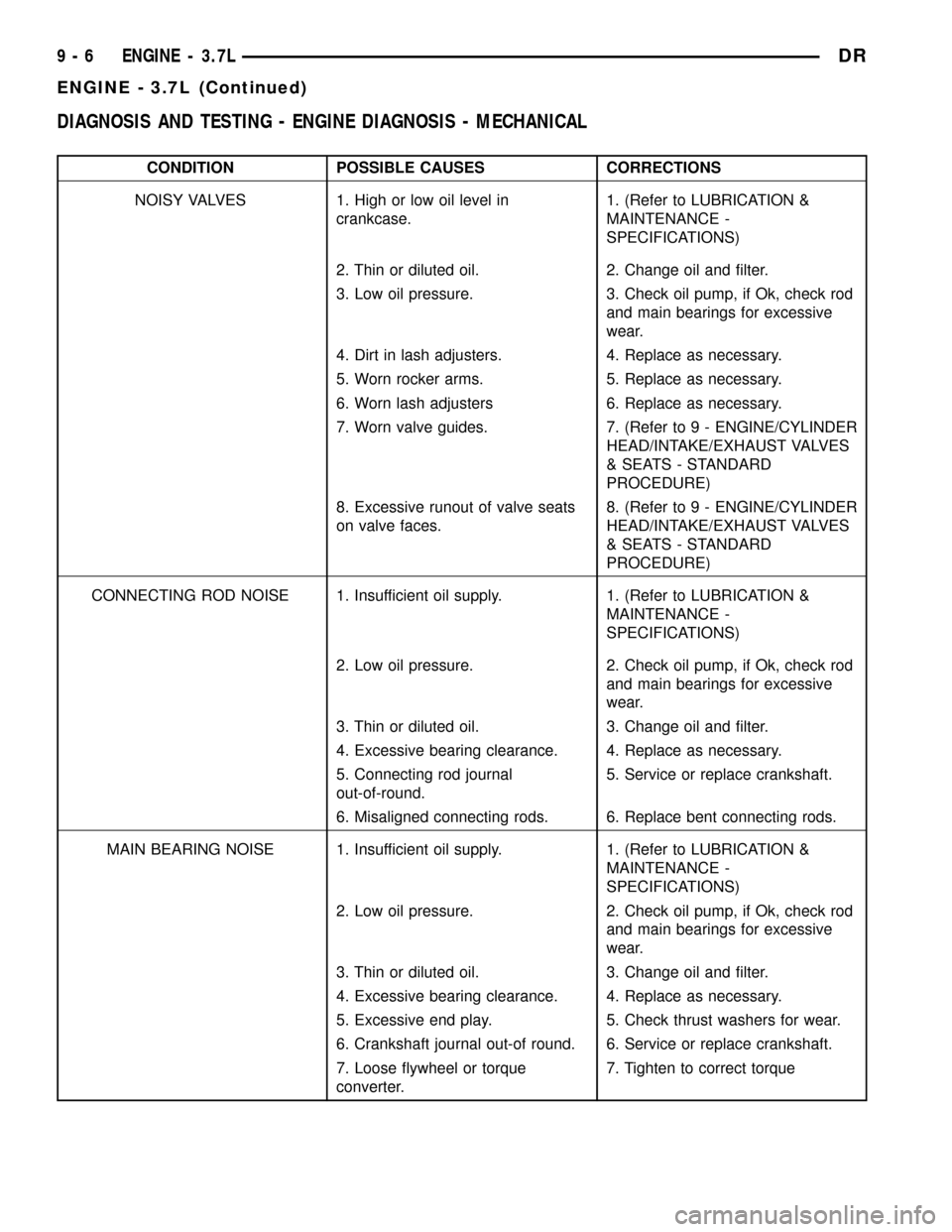
DIAGNOSIS AND TESTING - ENGINE DIAGNOSIS - MECHANICAL
CONDITION POSSIBLE CAUSES CORRECTIONS
NOISY VALVES 1. High or low oil level in
crankcase.1. (Refer to LUBRICATION &
MAINTENANCE -
SPECIFICATIONS)
2. Thin or diluted oil. 2. Change oil and filter.
3. Low oil pressure. 3. Check oil pump, if Ok, check rod
and main bearings for excessive
wear.
4. Dirt in lash adjusters. 4. Replace as necessary.
5. Worn rocker arms. 5. Replace as necessary.
6. Worn lash adjusters 6. Replace as necessary.
7. Worn valve guides. 7. (Refer to 9 - ENGINE/CYLINDER
HEAD/INTAKE/EXHAUST VALVES
& SEATS - STANDARD
PROCEDURE)
8. Excessive runout of valve seats
on valve faces.8. (Refer to 9 - ENGINE/CYLINDER
HEAD/INTAKE/EXHAUST VALVES
& SEATS - STANDARD
PROCEDURE)
CONNECTING ROD NOISE 1. Insufficient oil supply. 1. (Refer to LUBRICATION &
MAINTENANCE -
SPECIFICATIONS)
2. Low oil pressure. 2. Check oil pump, if Ok, check rod
and main bearings for excessive
wear.
3. Thin or diluted oil. 3. Change oil and filter.
4. Excessive bearing clearance. 4. Replace as necessary.
5. Connecting rod journal
out-of-round.5. Service or replace crankshaft.
6. Misaligned connecting rods. 6. Replace bent connecting rods.
MAIN BEARING NOISE 1. Insufficient oil supply. 1. (Refer to LUBRICATION &
MAINTENANCE -
SPECIFICATIONS)
2. Low oil pressure. 2. Check oil pump, if Ok, check rod
and main bearings for excessive
wear.
3. Thin or diluted oil. 3. Change oil and filter.
4. Excessive bearing clearance. 4. Replace as necessary.
5. Excessive end play. 5. Check thrust washers for wear.
6. Crankshaft journal out-of round. 6. Service or replace crankshaft.
7. Loose flywheel or torque
converter.7. Tighten to correct torque
9 - 6 ENGINE - 3.7LDR
ENGINE - 3.7L (Continued)
Page 1230 of 2627
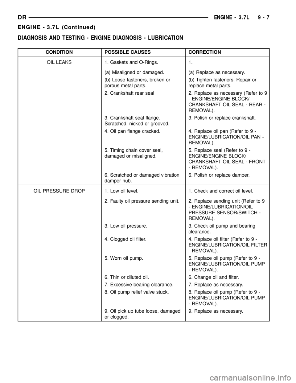
DIAGNOSIS AND TESTING - ENGINE DIAGNOSIS - LUBRICATION
CONDITION POSSIBLE CAUSES CORRECTION
OIL LEAKS 1. Gaskets and O-Rings. 1.
(a) Misaligned or damaged. (a) Replace as necessary.
(b) Loose fasteners, broken or
porous metal parts.(b) Tighten fasteners, Repair or
replace metal parts.
2. Crankshaft rear seal 2. Replace as necessary (Refer to 9
- ENGINE/ENGINE BLOCK/
CRANKSHAFT OIL SEAL - REAR -
REMOVAL).
3. Crankshaft seal flange.
Scratched, nicked or grooved.3. Polish or replace crankshaft.
4. Oil pan flange cracked. 4. Replace oil pan (Refer to 9 -
ENGINE/LUBRICATION/OIL PAN -
REMOVAL).
5. Timing chain cover seal,
damaged or misaligned.5. Replace seal (Refer to 9 -
ENGINE/ENGINE BLOCK/
CRANKSHAFT OIL SEAL - FRONT
- REMOVAL).
6. Scratched or damaged vibration
damper hub.6. Polish or replace damper.
OIL PRESSURE DROP 1. Low oil level. 1. Check and correct oil level.
2. Faulty oil pressure sending unit. 2. Replace sending unit (Refer to 9
- ENGINE/LUBRICATION/OIL
PRESSURE SENSOR/SWITCH -
REMOVAL).
3. Low oil pressure. 3. Check oil pump and bearing
clearance.
4. Clogged oil filter. 4. Replace oil filter (Refer to 9 -
ENGINE/LUBRICATION/OIL FILTER
- REMOVAL).
5. Worn oil pump. 5. Replace oil pump (Refer to 9 -
ENGINE/LUBRICATION/OIL PUMP
- REMOVAL).
6. Thin or diluted oil. 6. Change oil and filter.
7. Excessive bearing clearance. 7. Replace as necessary.
8. Oil pump relief valve stuck. 8. Replace oil pump (Refer to 9 -
ENGINE/LUBRICATION/OIL PUMP
- REMOVAL).
9. Oil pick up tube loose, damaged
or clogged.9. Replace as necessary.
DRENGINE - 3.7L 9 - 7
ENGINE - 3.7L (Continued)
Page 1231 of 2627
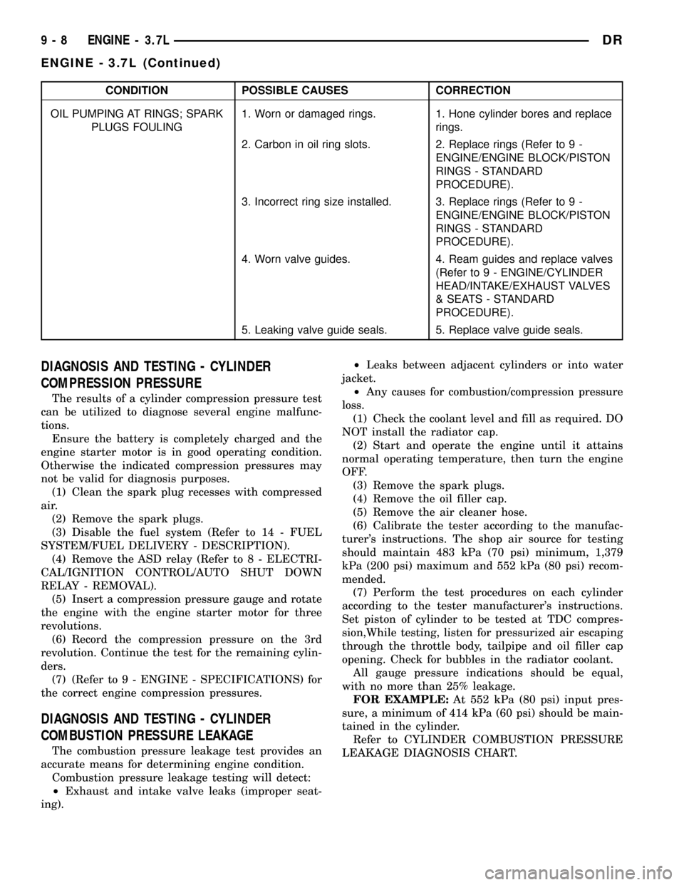
CONDITION POSSIBLE CAUSES CORRECTION
OIL PUMPING AT RINGS; SPARK
PLUGS FOULING1. Worn or damaged rings. 1. Hone cylinder bores and replace
rings.
2. Carbon in oil ring slots. 2. Replace rings (Refer to 9 -
ENGINE/ENGINE BLOCK/PISTON
RINGS - STANDARD
PROCEDURE).
3. Incorrect ring size installed. 3. Replace rings (Refer to 9 -
ENGINE/ENGINE BLOCK/PISTON
RINGS - STANDARD
PROCEDURE).
4. Worn valve guides. 4. Ream guides and replace valves
(Refer to 9 - ENGINE/CYLINDER
HEAD/INTAKE/EXHAUST VALVES
& SEATS - STANDARD
PROCEDURE).
5. Leaking valve guide seals. 5. Replace valve guide seals.
DIAGNOSIS AND TESTING - CYLINDER
COMPRESSION PRESSURE
The results of a cylinder compression pressure test
can be utilized to diagnose several engine malfunc-
tions.
Ensure the battery is completely charged and the
engine starter motor is in good operating condition.
Otherwise the indicated compression pressures may
not be valid for diagnosis purposes.
(1) Clean the spark plug recesses with compressed
air.
(2) Remove the spark plugs.
(3) Disable the fuel system (Refer to 14 - FUEL
SYSTEM/FUEL DELIVERY - DESCRIPTION).
(4) Remove the ASD relay (Refer to 8 - ELECTRI-
CAL/IGNITION CONTROL/AUTO SHUT DOWN
RELAY - REMOVAL).
(5) Insert a compression pressure gauge and rotate
the engine with the engine starter motor for three
revolutions.
(6) Record the compression pressure on the 3rd
revolution. Continue the test for the remaining cylin-
ders.
(7) (Refer to 9 - ENGINE - SPECIFICATIONS) for
the correct engine compression pressures.
DIAGNOSIS AND TESTING - CYLINDER
COMBUSTION PRESSURE LEAKAGE
The combustion pressure leakage test provides an
accurate means for determining engine condition.
Combustion pressure leakage testing will detect:
²Exhaust and intake valve leaks (improper seat-
ing).²Leaks between adjacent cylinders or into water
jacket.
²Any causes for combustion/compression pressure
loss.
(1) Check the coolant level and fill as required. DO
NOT install the radiator cap.
(2) Start and operate the engine until it attains
normal operating temperature, then turn the engine
OFF.
(3) Remove the spark plugs.
(4) Remove the oil filler cap.
(5) Remove the air cleaner hose.
(6) Calibrate the tester according to the manufac-
turer's instructions. The shop air source for testing
should maintain 483 kPa (70 psi) minimum, 1,379
kPa (200 psi) maximum and 552 kPa (80 psi) recom-
mended.
(7) Perform the test procedures on each cylinder
according to the tester manufacturer's instructions.
Set piston of cylinder to be tested at TDC compres-
sion,While testing, listen for pressurized air escaping
through the throttle body, tailpipe and oil filler cap
opening. Check for bubbles in the radiator coolant.
All gauge pressure indications should be equal,
with no more than 25% leakage.
FOR EXAMPLE:At 552 kPa (80 psi) input pres-
sure, a minimum of 414 kPa (60 psi) should be main-
tained in the cylinder.
Refer to CYLINDER COMBUSTION PRESSURE
LEAKAGE DIAGNOSIS CHART.
9 - 8 ENGINE - 3.7LDR
ENGINE - 3.7L (Continued)
Page 1234 of 2627
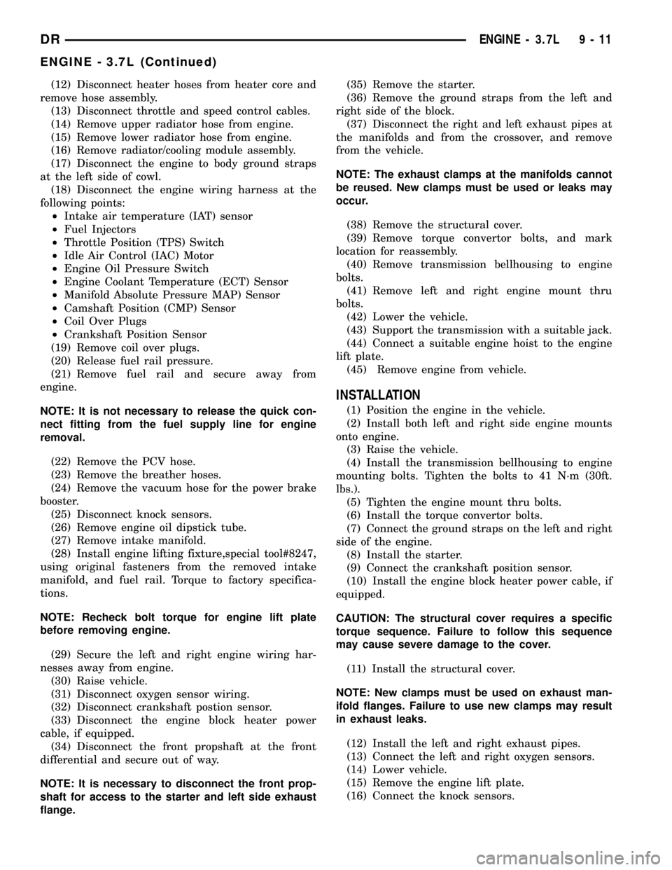
(12) Disconnect heater hoses from heater core and
remove hose assembly.
(13) Disconnect throttle and speed control cables.
(14) Remove upper radiator hose from engine.
(15) Remove lower radiator hose from engine.
(16) Remove radiator/cooling module assembly.
(17) Disconnect the engine to body ground straps
at the left side of cowl.
(18) Disconnect the engine wiring harness at the
following points:
²Intake air temperature (IAT) sensor
²Fuel Injectors
²Throttle Position (TPS) Switch
²Idle Air Control (IAC) Motor
²Engine Oil Pressure Switch
²Engine Coolant Temperature (ECT) Sensor
²Manifold Absolute Pressure MAP) Sensor
²Camshaft Position (CMP) Sensor
²Coil Over Plugs
²Crankshaft Position Sensor
(19) Remove coil over plugs.
(20) Release fuel rail pressure.
(21) Remove fuel rail and secure away from
engine.
NOTE: It is not necessary to release the quick con-
nect fitting from the fuel supply line for engine
removal.
(22) Remove the PCV hose.
(23) Remove the breather hoses.
(24) Remove the vacuum hose for the power brake
booster.
(25) Disconnect knock sensors.
(26) Remove engine oil dipstick tube.
(27) Remove intake manifold.
(28) Install engine lifting fixture,special tool#8247,
using original fasteners from the removed intake
manifold, and fuel rail. Torque to factory specifica-
tions.
NOTE: Recheck bolt torque for engine lift plate
before removing engine.
(29) Secure the left and right engine wiring har-
nesses away from engine.
(30) Raise vehicle.
(31) Disconnect oxygen sensor wiring.
(32) Disconnect crankshaft postion sensor.
(33) Disconnect the engine block heater power
cable, if equipped.
(34) Disconnect the front propshaft at the front
differential and secure out of way.
NOTE: It is necessary to disconnect the front prop-
shaft for access to the starter and left side exhaust
flange.(35) Remove the starter.
(36) Remove the ground straps from the left and
right side of the block.
(37) Disconnect the right and left exhaust pipes at
the manifolds and from the crossover, and remove
from the vehicle.
NOTE: The exhaust clamps at the manifolds cannot
be reused. New clamps must be used or leaks may
occur.
(38) Remove the structural cover.
(39) Remove torque convertor bolts, and mark
location for reassembly.
(40) Remove transmission bellhousing to engine
bolts.
(41) Remove left and right engine mount thru
bolts.
(42) Lower the vehicle.
(43) Support the transmission with a suitable jack.
(44) Connect a suitable engine hoist to the engine
lift plate.
(45) Remove engine from vehicle.
INSTALLATION
(1) Position the engine in the vehicle.
(2) Install both left and right side engine mounts
onto engine.
(3) Raise the vehicle.
(4) Install the transmission bellhousing to engine
mounting bolts. Tighten the bolts to 41 N´m (30ft.
lbs.).
(5) Tighten the engine mount thru bolts.
(6) Install the torque convertor bolts.
(7) Connect the ground straps on the left and right
side of the engine.
(8) Install the starter.
(9) Connect the crankshaft position sensor.
(10) Install the engine block heater power cable, if
equipped.
CAUTION: The structural cover requires a specific
torque sequence. Failure to follow this sequence
may cause severe damage to the cover.
(11) Install the structural cover.
NOTE: New clamps must be used on exhaust man-
ifold flanges. Failure to use new clamps may result
in exhaust leaks.
(12) Install the left and right exhaust pipes.
(13) Connect the left and right oxygen sensors.
(14) Lower vehicle.
(15) Remove the engine lift plate.
(16) Connect the knock sensors.
DRENGINE - 3.7L 9 - 11
ENGINE - 3.7L (Continued)